Embedded Networking & Communications
Objectives for Week 13
- Individual Assignment : Design, build, and connect wired or wireless node(s) with network or bus addresses and local input &/or output device(s)
- Group Assignment: Send a message between two projects
I2C Protocol
This week, my primary goal is to gain a deeper understanding of I2C and other serial communication protocols, as I believe they are crucial for my project. Specifically, I aim to create a network of interconnected boards that can communicate smoothly using these protocols. After evaluating my options, I chose to work with the ATtiny1614 chips, which are widely available and easy to use. I also have prior experience with this chip from my work during the electronics design and manufacturing week. Considering these factors, I'm excited to move forward with my design, leveraging the capabilities of the ATtiny1614 and the power of I2C and serial communication to create a strong network of boards that can exchange data and work together seamlessly. This ambitious project promises to open up new possibilities and significantly enhance my project's potential, and I'm eager to devote this week to making it a reality.
Imagine a simple network with a single boss (Leader) and several workers (followers). The boss controls the conversation, but everyone can talk (bidirectional data transfer).
To make this work, they only need two wires:
- One wire (SDA) carries the messages.
- The other wire (SCL) keeps everyone in sync like a metronome (clock signals).
With these wires and a clear leader, devices on the I2C network can exchange information smoothly. Knowing who's in charge (Leader-follower) and how they use the wires (SDA and SCL) is key to using I2C effectively. This lets devices on the network work together and share data efficiently.
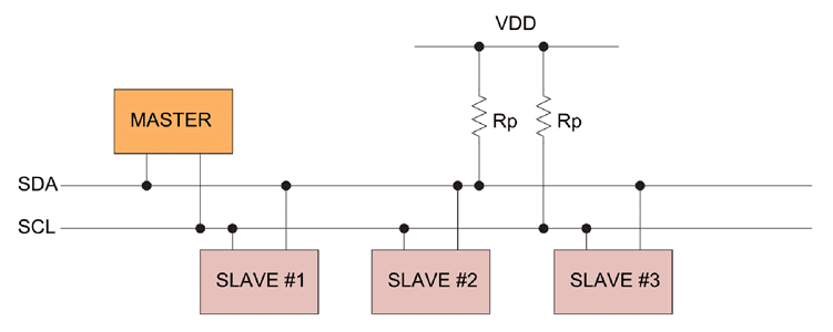
I got this image from Internet , i feel "Master" & " Slave " is unparlimentary. So In my documentation i am using " Leader" & "Follower"
ATtiny1614
The ATtiny1614 is a tiny microcontroller, like a mini computer brain. It's got 16KB of space for instructions and 2KB of scratchpad memory. It can run at speeds of 20MHz and uses minimal power. Imagine a small, powerful brain with low energy needs!
.jpg)
Schematic Design
Leader Board
I'm using the board that I designed during Electronics Design week as the Leader
_(1).jpeg)
Refer documentation of Week 8 to know about the board.
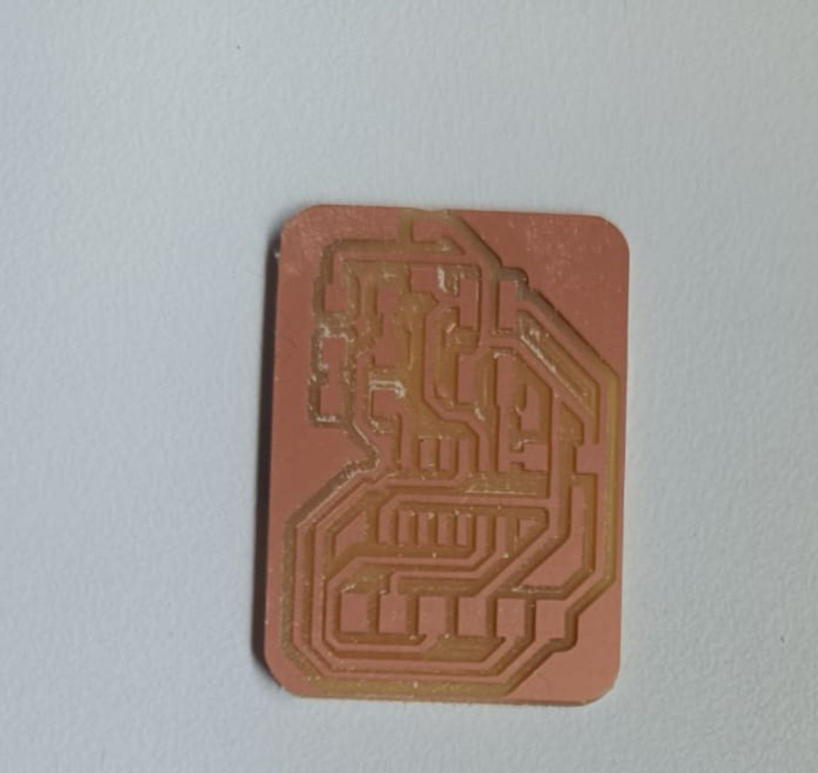
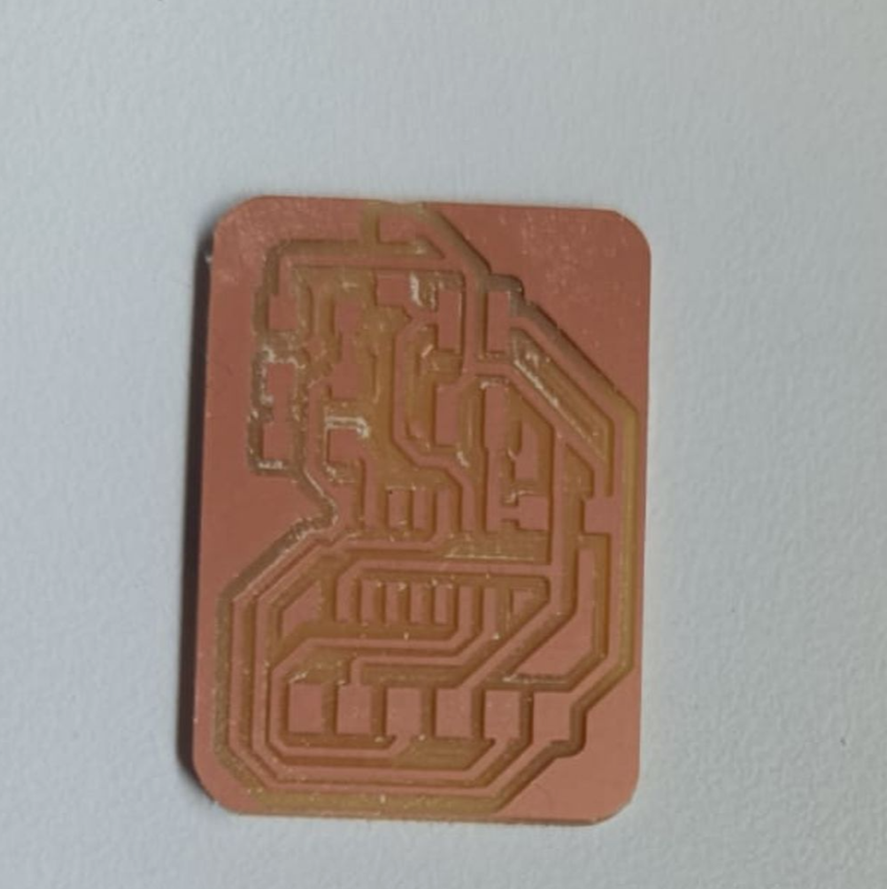
follower Boards
.png)
.png)
Gerber to PNG
Next step is to export the Gerber file and convert it into PNG for milling. Our FabLab has a special website for this conversion. Visit this website.
Using the options, chose top layer and top cut and generate the png files.
.png)
Milling
In week four of electronics production, I learned how to mill PCBs (printed circuit boards) using a Roland Modela MDX20 machine. I'll be using the same process this time
So I requested for all components on FabLab Inventory Website and acquired them.
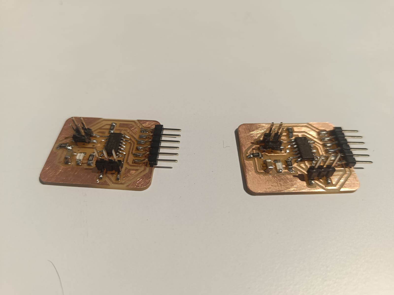
.jpeg)
After Soldering ,here is the final result
Programming
For programming i iwas bootloaded the code for Leader board first, then bootloaded the follower boards
Problem faced
While connecting the follower board My port were turned off due to short circuit. Then i cross-checked the design again , Oh nooooooooo !!!!!! I missed one trace path.
.png)
Byresoldering the path using copper wires i have fixed the issue of my PCB
.jpeg)
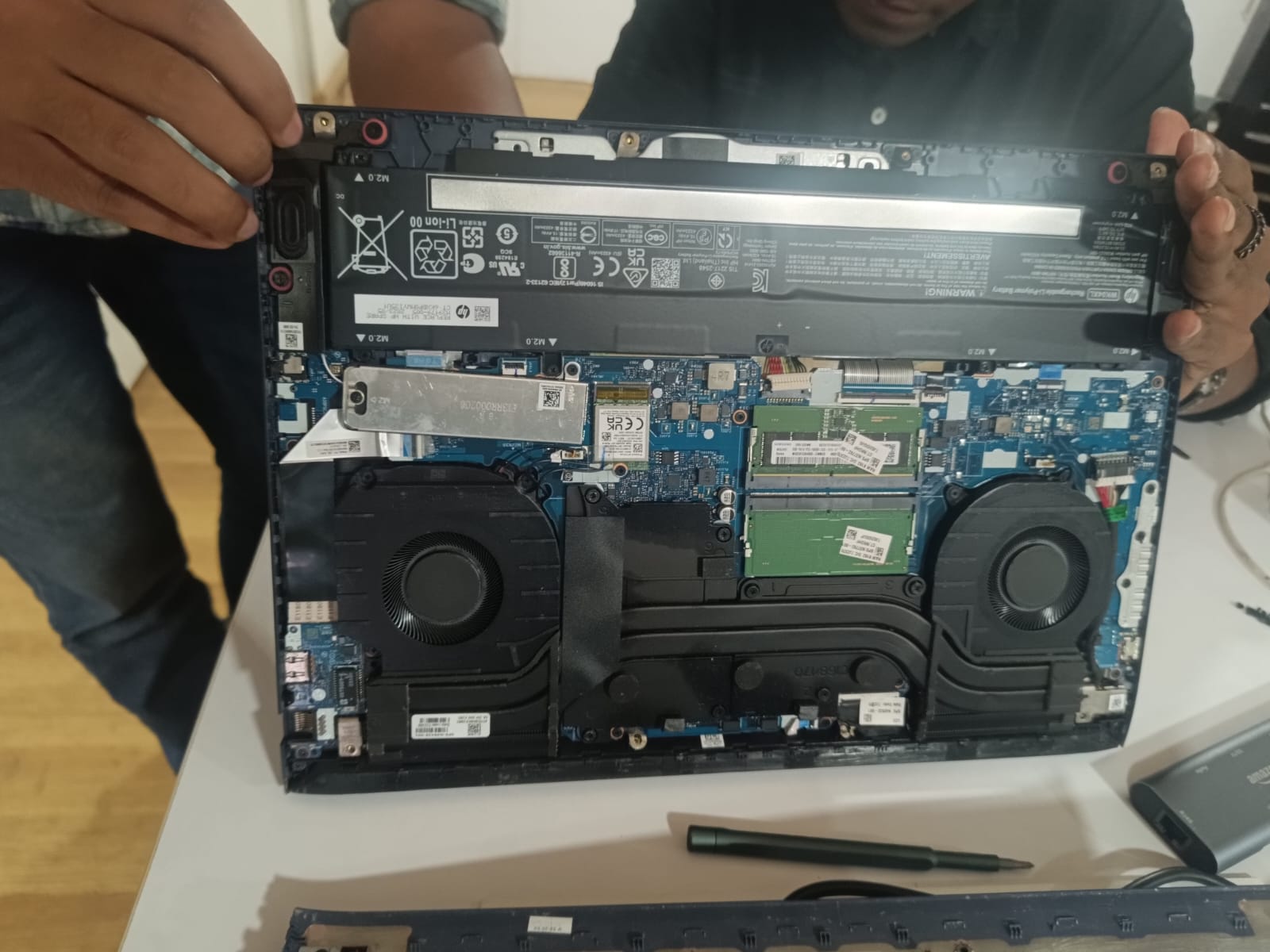
I need to quickly repair the laptop ports, which are malfunctioning due to high voltage, by reinstalling the battery.
Next, I connected the Leader board with the followers and began working on the software side of the project.
Code for Leader Board
  #include <Wire.h >

        int i = 0;
        int j = 0;

        int led = 2;

        void setup() {
            Serial.begin(9600);
            Wire.begin();

            pinMode(led, OUTPUT); // led
        }

        void loop()
        {

            for (i = 0; i <= 3; i++) { // 0,1,2,3

            Wire.beginTransmission(8); //follower number 8
            if ( i == 1) {
                Wire.write(1);
                Serial.println("1");
            } else {
                Wire.write(0);
                Serial.println("0");
            }
            Wire.endTransmission();

            Wire.beginTransmission(9); //follower number 8
            if ( i == 2) {
                Wire.write(1);
                Serial.println("1");
            } else {
                Wire.write(0);
                Serial.println("0");
            }
            Wire.endTransmission();

            for (j = 0; j <= i; j++) { // blink i times
                digitalWrite(led, HIGH);
                delay(200);
                digitalWrite(led, LOW);
                delay(200);
            }

            delay(1000);
            }

        }
Code for follower 1
    #include <Wire.h >
    #define led 10
    int d1=0;

    void setup() {
        pinMode(led, OUTPUT);
        Serial.begin(9600);
        Wire.begin(8); // change address
        Wire.onReceive(receiveEvent);
    }

    void loop() {
        if (d1 == 1) {
        digitalWrite(led, HIGH);
        } else {
        digitalWrite(led, LOW);
        }
        delay(500);
    }

    void receiveEvent(int howMany) {
        while (Wire.available()) {
        d1 = Wire.read();
        }
    }
Code for follower 2
#include <Wire.h >
    int servo = 0;
    int d1=0;
    int angle;
    int pwm;

    void setup() {
        pinMode(servo, OUTPUT);
        Serial.begin(9600);
        Wire.begin(9); // change address
        Wire.onReceive(receiveEvent);
    }

    void loop() {
        if (d1 == 1) {
        for (angle = 0; angle <= 140; angle += 10)  {
            servoPulse(servo, angle);  }
        for (angle = 140; angle >= 0; angle -= 10)  {
            servoPulse(servo, angle);  }
        } else {

        }
        delay(500);
    }

    void receiveEvent(int howMany) {
        while (Wire.available()) {
        d1 = Wire.read();
        }
    }

    void servoPulse (int servo, int angle)
    {
        pwm = (angle*11) + 500;      // Convert angle to microseconds
        digitalWrite(servo, HIGH);
        delayMicroseconds(pwm);
        digitalWrite(servo, LOW);
        delay(50);                   // Refresh cycle of servo
    }
Finally i got the communication results
Group assignment:
Send a message between two projects click here for group assignment
.png)