Molding & Casting
Tasks for Week
- Group Assignment:
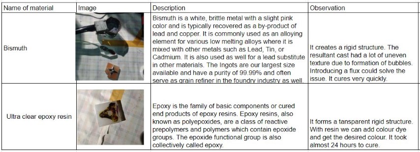
- Review the safety data sheets for each of your molding and casting materials, then make and compare test casts with each of them
- Compare printing vs. machining molds
- Design a mold around the process we'll be using
- Produce it with a smooth surface finish and use it to cast parts
- extra credit: use more then two mold parts
Group Assignment
This week's group assingment was to review the safety data sheets for each of the molding and casting materials and then compare their test casts and also to compare printing and machining molds.
For further details, click on the link -Group Assignment-Week 12
Molding and casting are fundamental processes in the manufacturing sector. With the use of computer-aided design and manufacturing (CAD/CAM) technology, molds can be produced. In the past, artisans would craft original models, then make molds from them to generate multiple identical replicas.
For our assignment, we leverage CAD/CAM to create a 3D digital model of a design, which is then used to control a CNC machine that carves the design into a block of machinable wax. This wax mold serves as the basis for casting different materials, including plastics and metals. This method is widely employed in industries like automotive, aerospace, and medical, where precise and intricate shapes are crucial for various parts and components.
Design
When it came to design, I decided to create an emoji that I often use in my chats—😍. I used Fusion 360 to model it,
.png)
I have drawn above the image and extruded it
.png)
Then i have arranged the design into the wax mould size
.png)
CAM
Fusion 360's CAM features enable users to ready their designs for manufacturing on various machines, such as CNC routers, milling machines, lathes, and others. In this scenario, I will utilize the CAM to mill a design on a wax block using a DPM RX 2 Vertical Milling Machine.
The CAM workspace in Fusion 360 is dedicated to milling operations, where users can choose cutting tools, define material properties, and establish machining parameters. In this workspace, users can create and adjust toolpaths, which dictate the movements of the cutting tool. The CAM workspace also includes a simulation tool to check the precision of the toolpaths, ensuring the machined outcome aligns with the intended specifications. After the toolpaths are created and validated through simulation, they can be exported as G-code, a programming language used to operate CNC machines. This G-code is then sent to the milling machine to guide the production of the physical part.
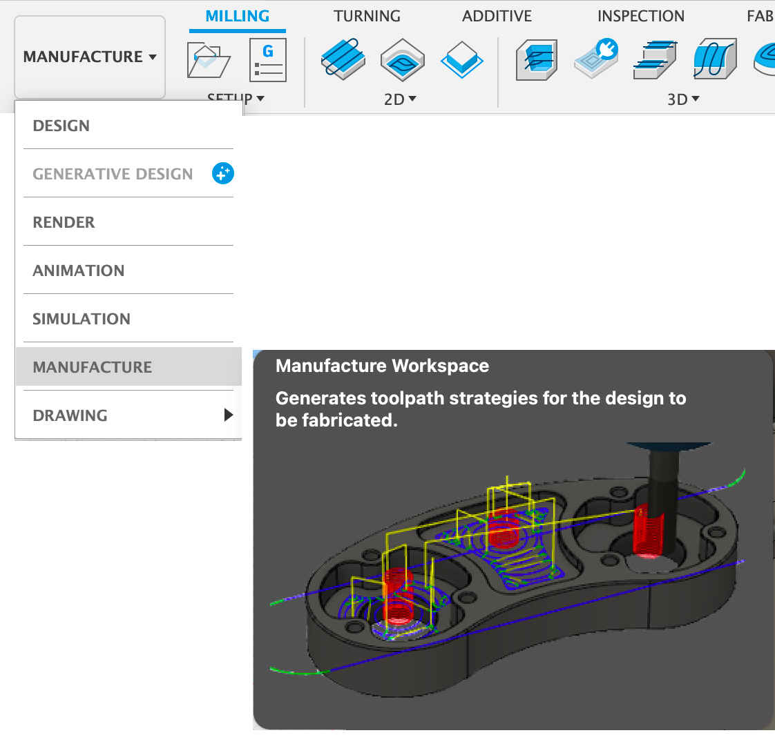
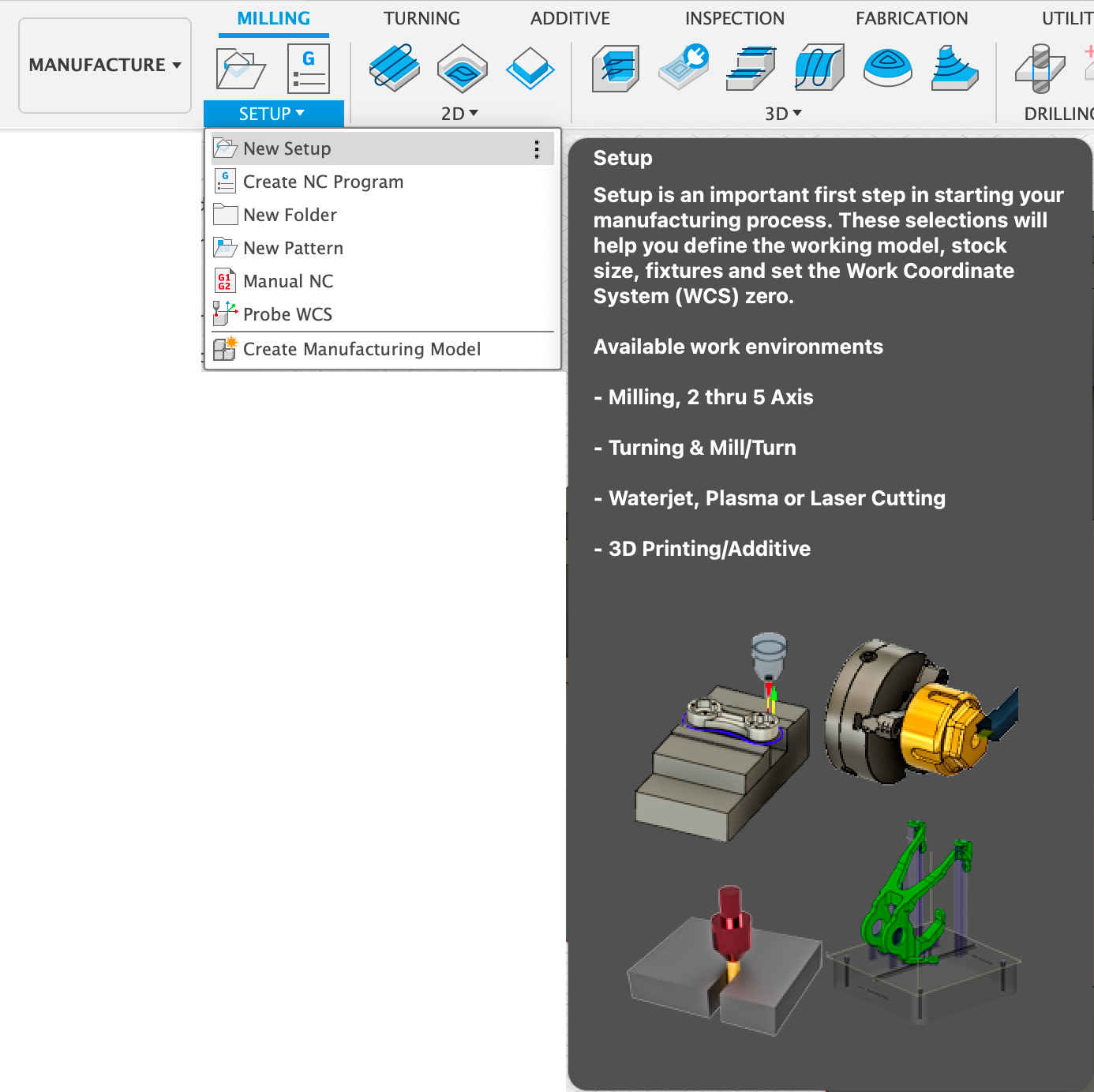
Step 1: Once the design is made, before moving into milling, we need to create CAM for machining. That is definig the toolpath. For thath we use Fusion 360 manufacture workspace. Go to Manufacture workspace from Design.
Step 2: Create New Setup
Step 3: While creating a new setup, we need to specify the stock material and size. Here we made a block in Fusion with exact dimension of our stock. And in Mode we can select the Relative size box.
.png)
Step 4: Once stock is created we need to add the tools.
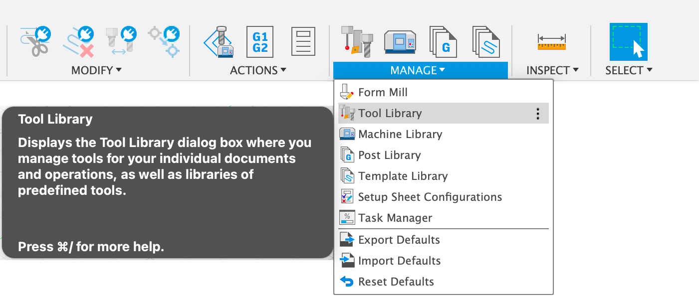
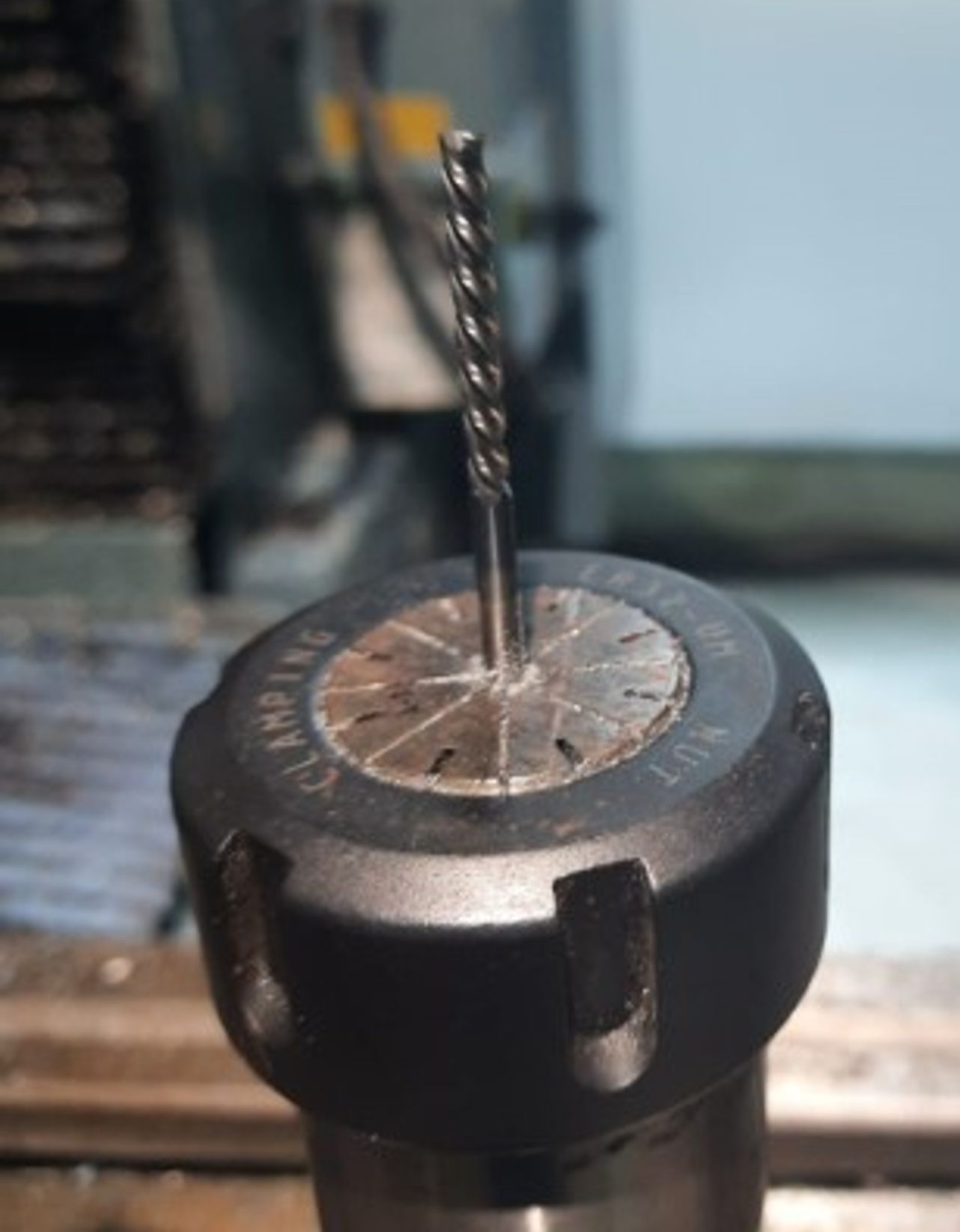
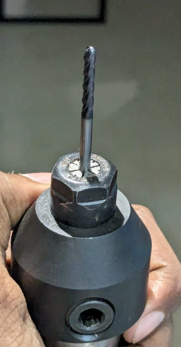
Step 5: Tools can be added according to the available stocks. I needed 3 bits, 6 mm flat end mill 3mm Flat End & 3mm Ball End. I added both with specification cross checked with the actual tools available. And added Holder as well.
.png)
Step 6: Once the tools are setup, now is the tie to play around the toolpaths. There are different option to chose according to the design.
Additional Common Settings:
Spindle Speed: 4000 rpm
Cutting Feedrate: 900 mm/min
Retraction Policy: Minimum Retraction
.png)
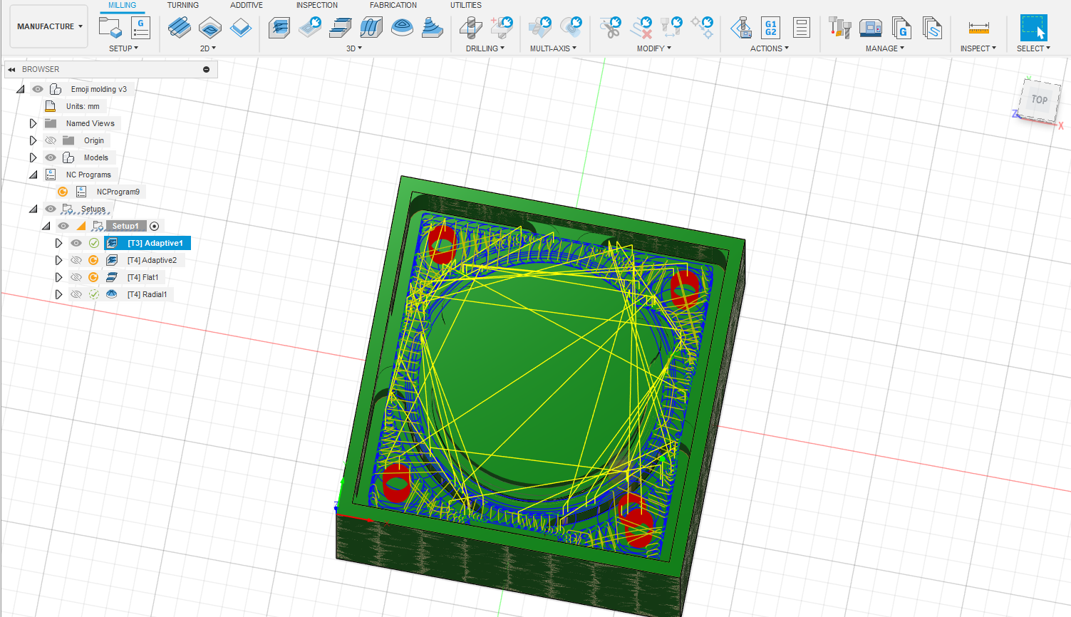
To remove the most amount of material, I used the 6mm flat end bit under 3D Adaptive clearing.
Then i have used Next, I used 3mm flat end bit and used it under three configurations to remove the material, same as 3D adaptive layer used above.
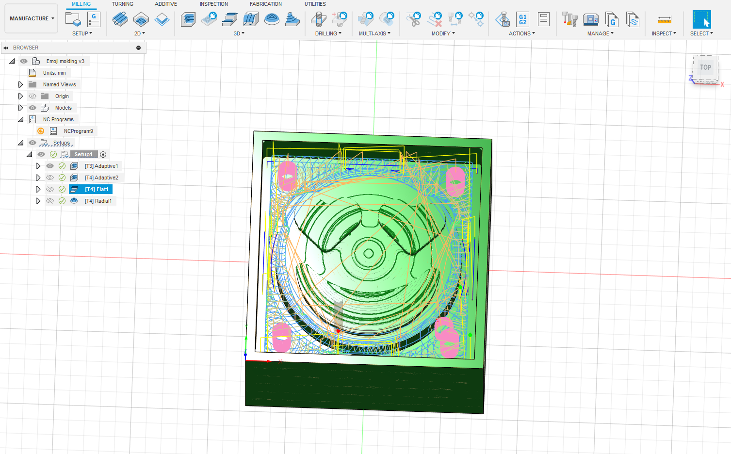
Then for the fianl step i have used ball end mill
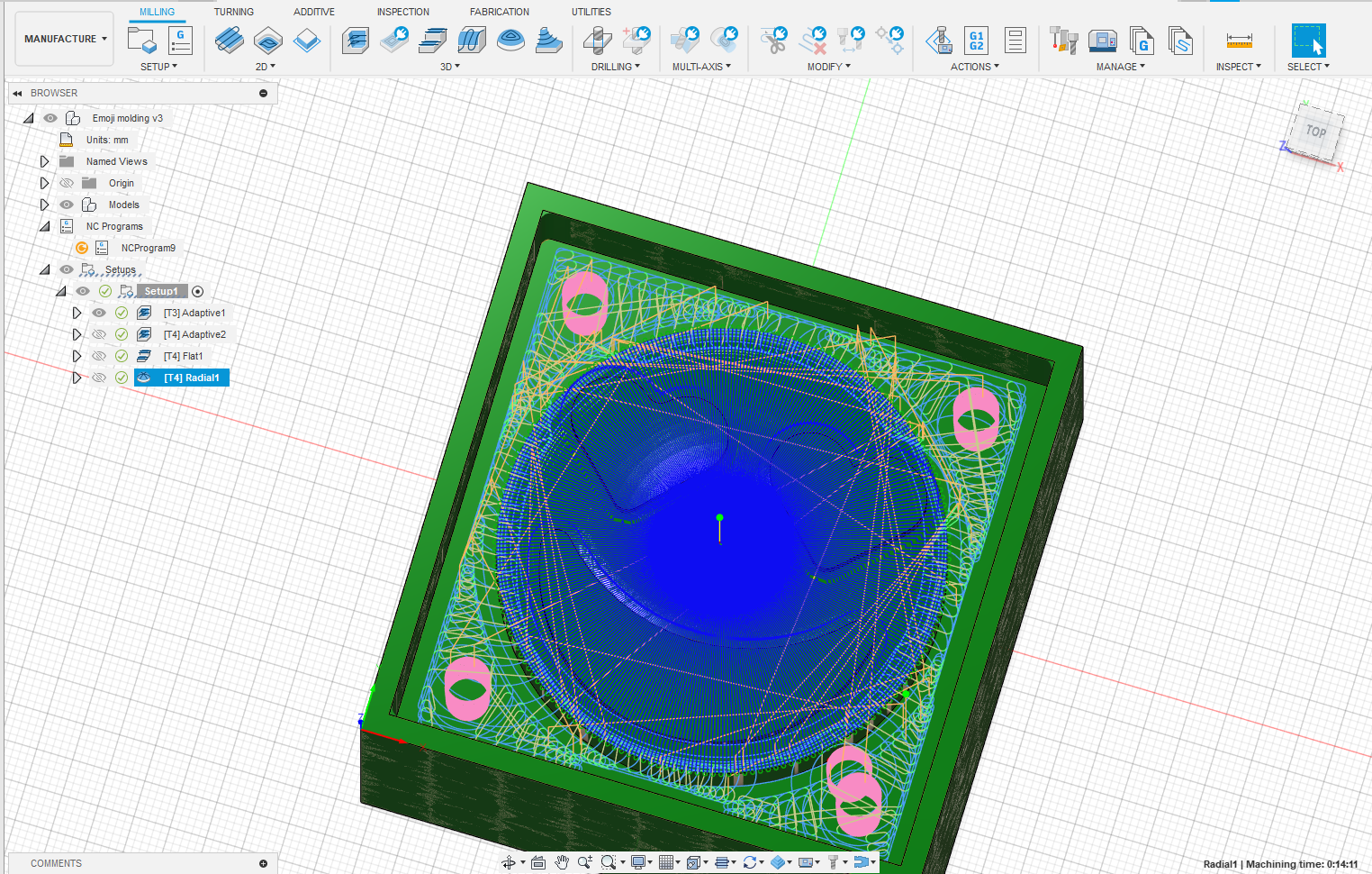
.png)
By right-clicking on each operation and selecting "Simulate," you can view the toolpath for that specific step.
Once everything was set up, the next move was to generate the G-codes. To do this, I right-clicked on the job and chose "Post Process." I then chose the location to save the G-code, picked the right tools, and proceeded to export the G-code. I ended up with only three sets of G-code because the second and third operations used the same tool, eliminating the need for a tool change between them.
Milling
DPM RX2 Vertical Milling Machine
The vertical milling machine is a precise tool utilized for shaping and fabricating by removing material, often from metallic workpieces. This process creates flat surfaces or specific features on a workpiece, usually with precise alignment to other components or surfaces.
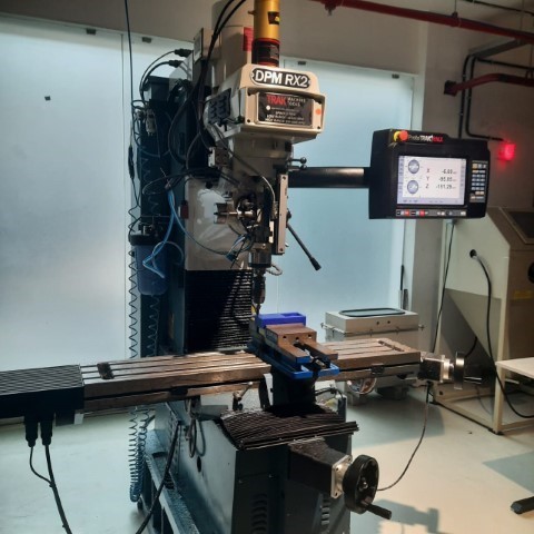
TRAK DPM RX2 Specifications:
- 49″ x 9″ table size
- 31.75″ X axis / 16″ Y axis / 25.5″ Z axis travel
- 3 HP continuous spindle motor
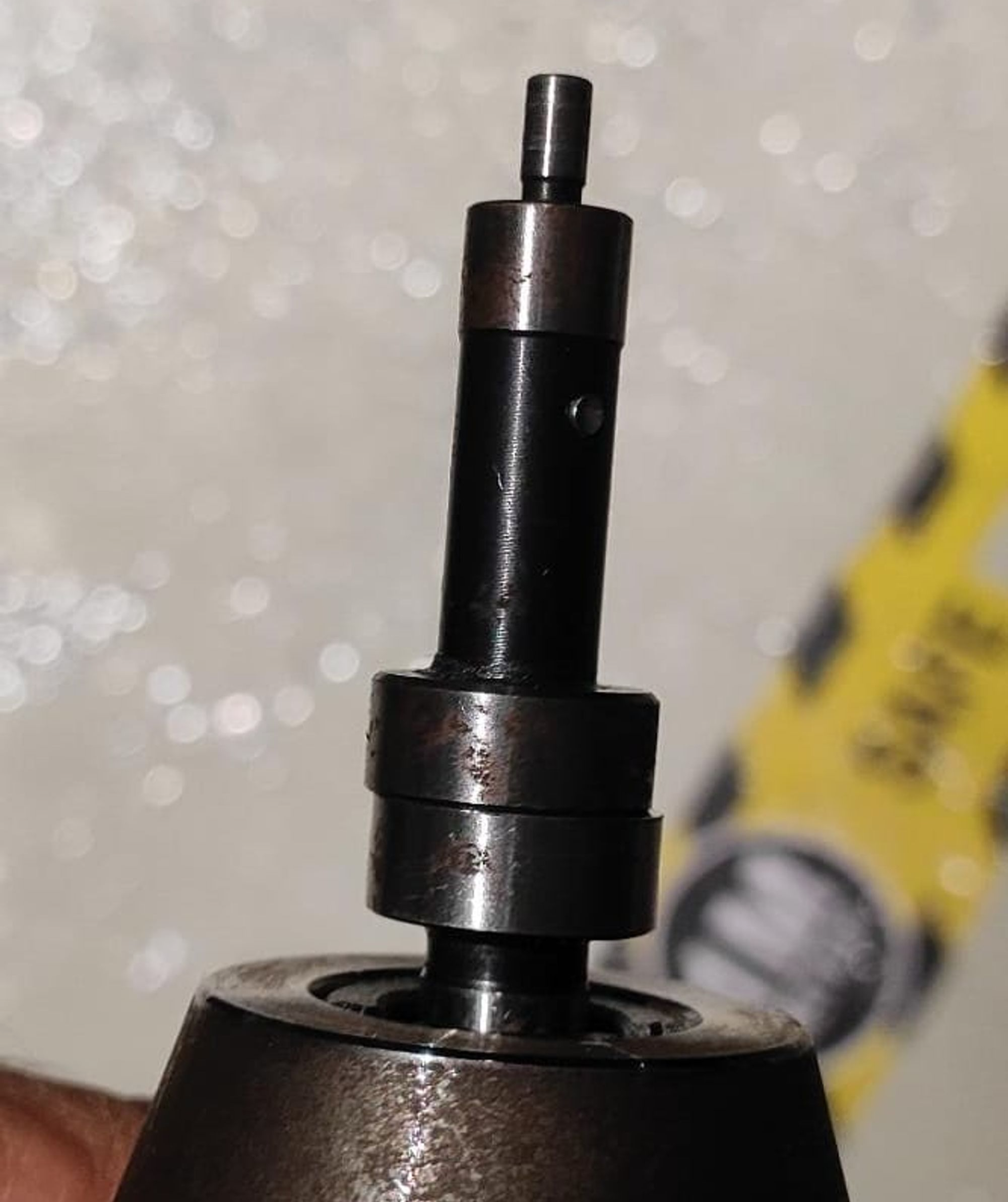
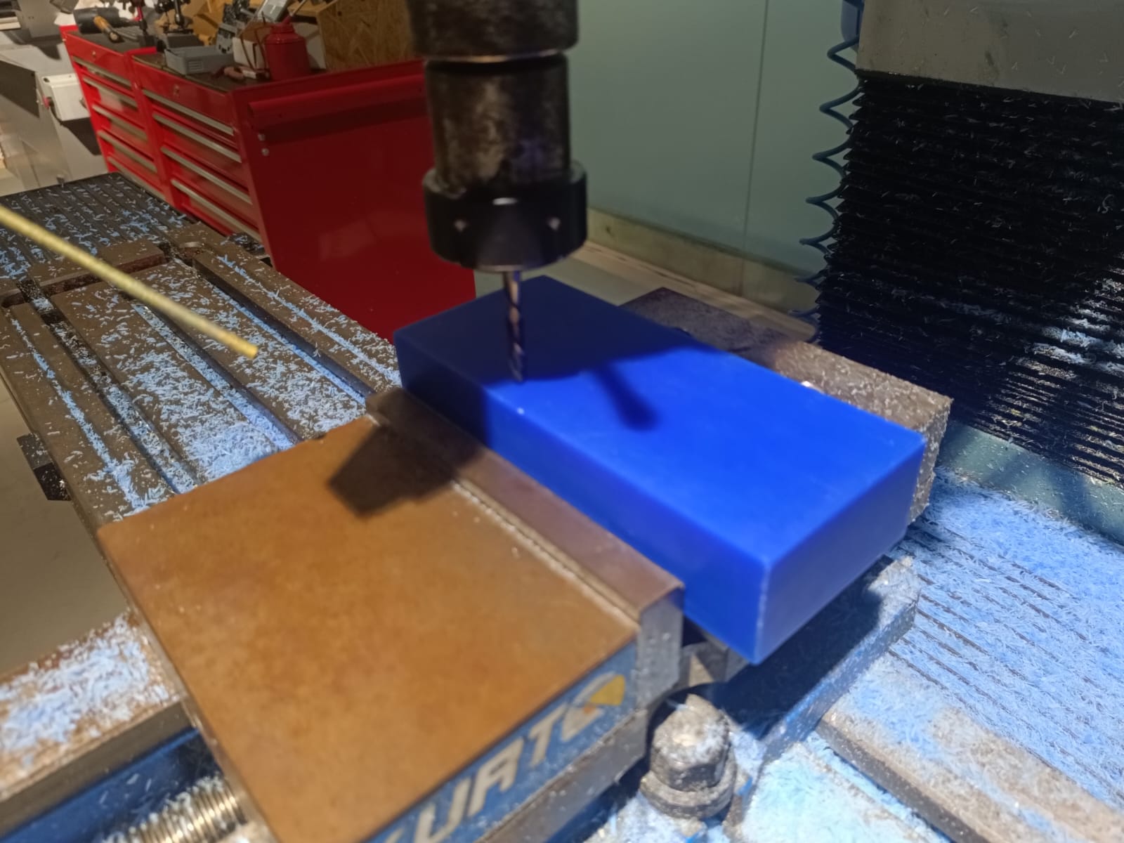
To set up the machine, first switch it on and place the workpiece on the machine vise. After fixing the material, we need to set the origin of the machine. This can be done by adding the tool offset of the machine after fixing the edge finder on the machine.
Once the origin is set, next step is to upload the program. Click on "Prog In/Out" on screen and add the file.
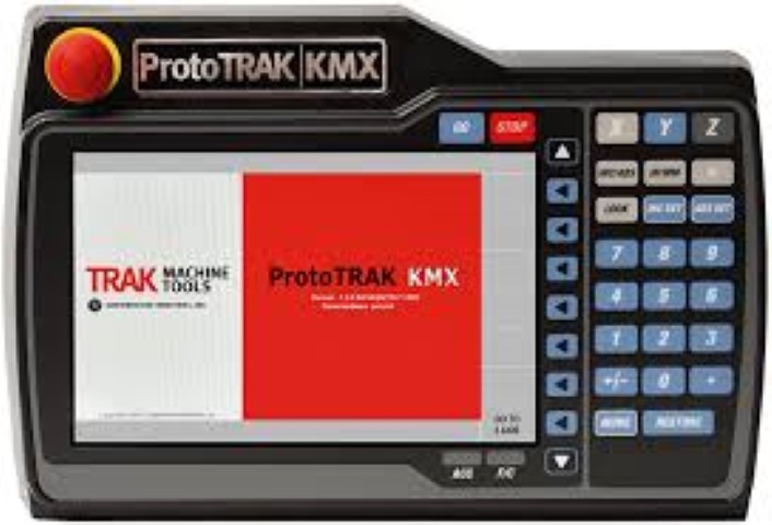
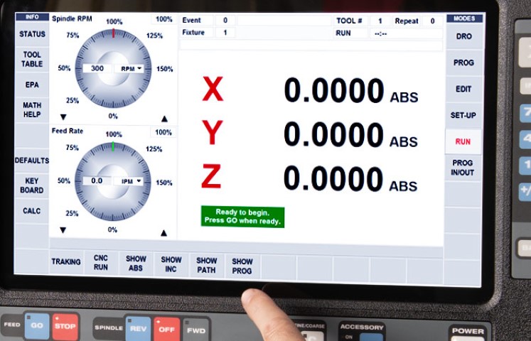
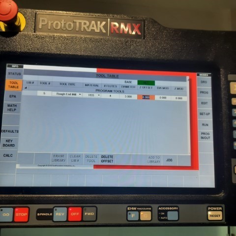
Next step is to add the tool details such as its diameter, number of flutes etc by clicking on "Tool Table".
Before running the codes directly, "traking" can be done to see if all the parameters given are right and if the work is done properly. Once satisfied, click on "CNC Run" for the machine to start milling.
For my design milling, I opted for 4 separate operations. All of these operations can be found under the 3D section in the toolbar.
Adaptive Clearing 1:
First I have used the 6 mm flat end mill
Results after 1st program
.jpeg)
Adaptive Clearing 2:
Mill Bit: 3mm Flat End Mill 4 Flutes
Flat:
Mill Bit: 3mm Flat End Mill 4 Flutes For the subsequent next operations, a 3mm flat end bit is inserted. And here is the output after using 3mm bit
Radial
Mill Bit: 3mm Ball Nose Mill 4 Flutes for finishing operations
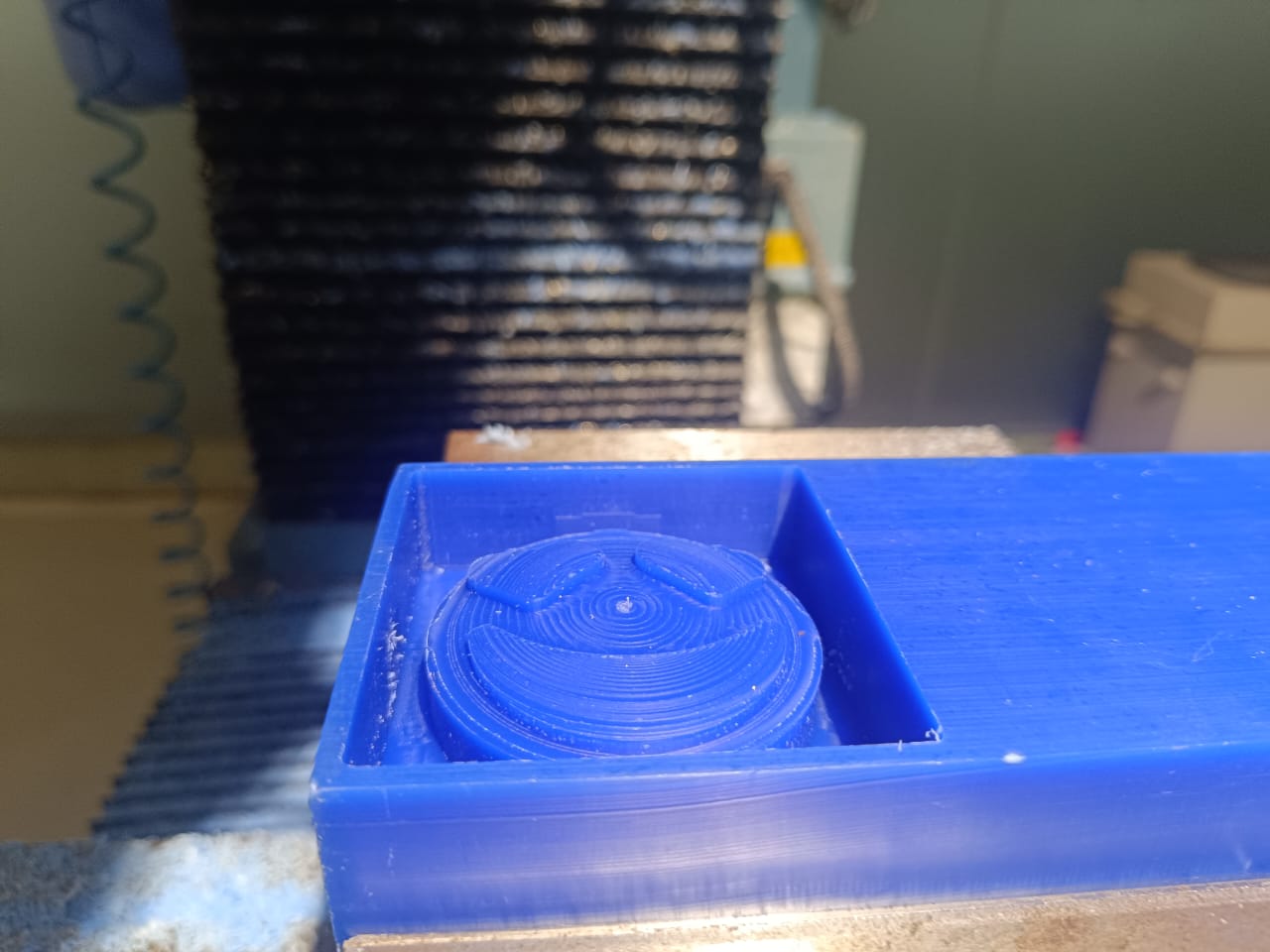
After using the final operation
Safety has to be ensured at each step. Wear gloves and goggles. Make sure not to wear loose clothes while working near the machine.
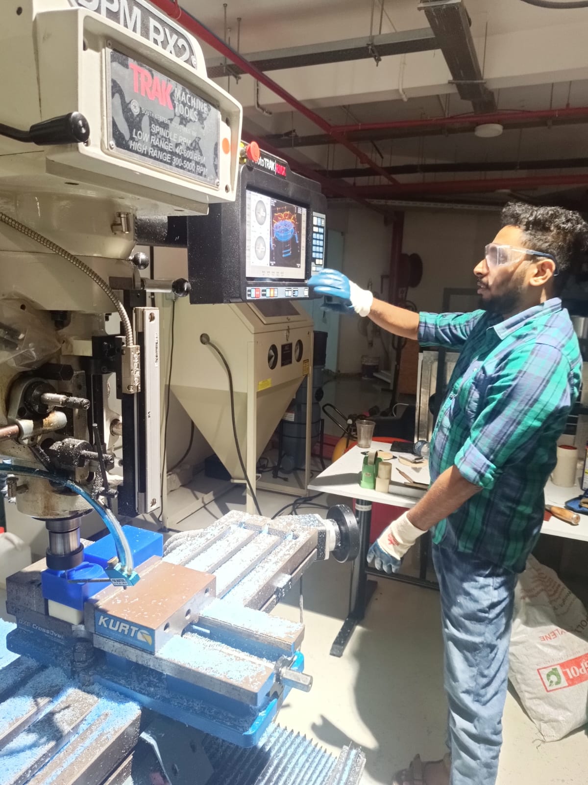
The machine provides an extra feature of giving a live visual representation of the toolpath during the process.
Finally i got the finished mold
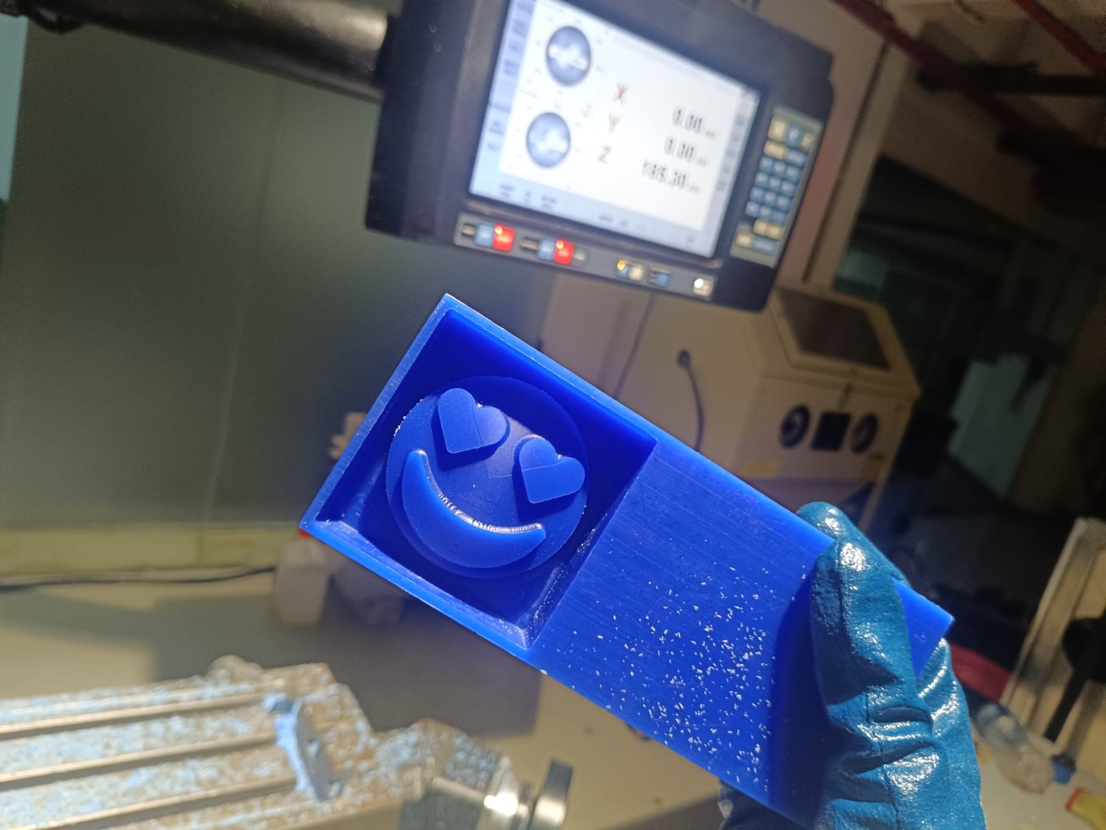
Molding
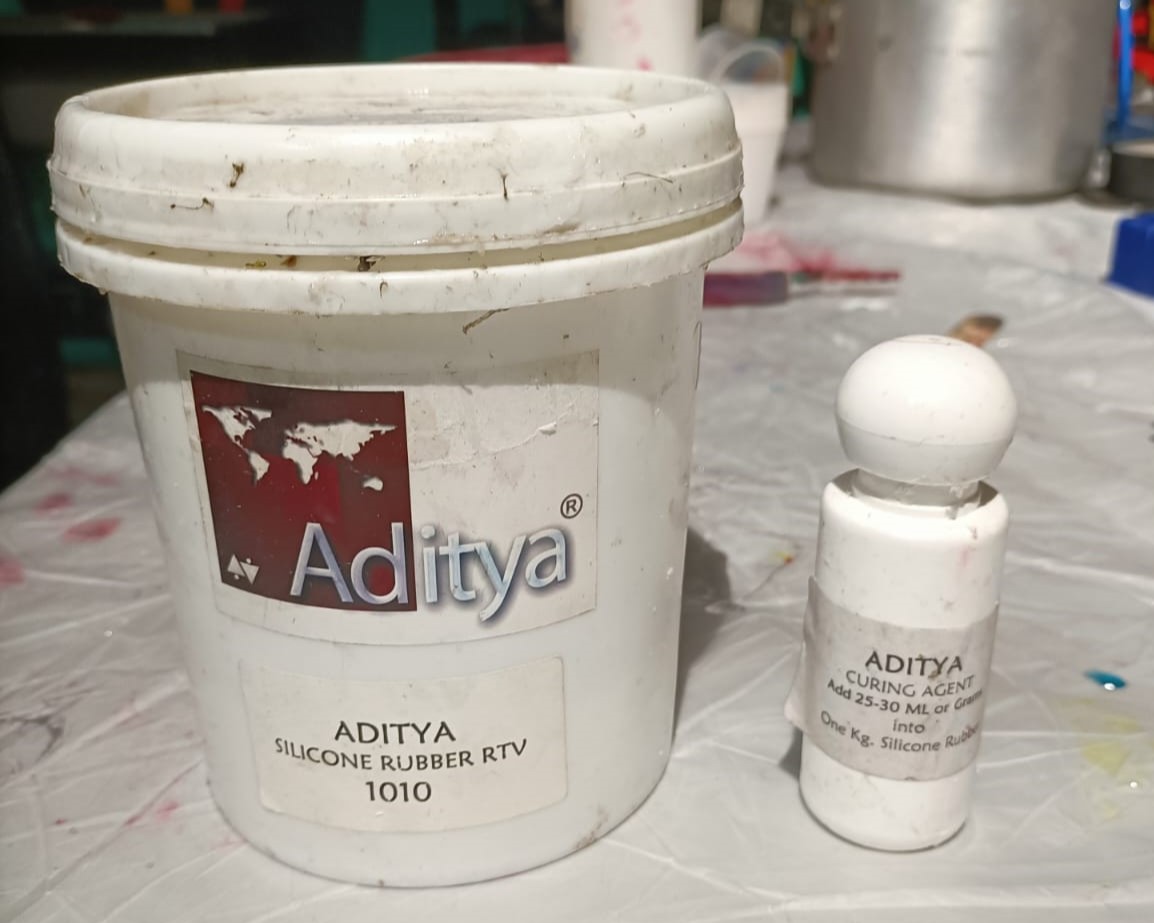
The next step involves creating a silicone mold.
1010 Silicone Rubber RTV (Room Temperature Vulcanizing) is a dedicated silicone rubber material designed for mold making and prototyping. This compound consists of two parts: a silicone rubber base and a curing agent. When mixed in the correct proportion of 100ml of silicone with 30ml of curing agent, the mixture begins to cure at room temperature.
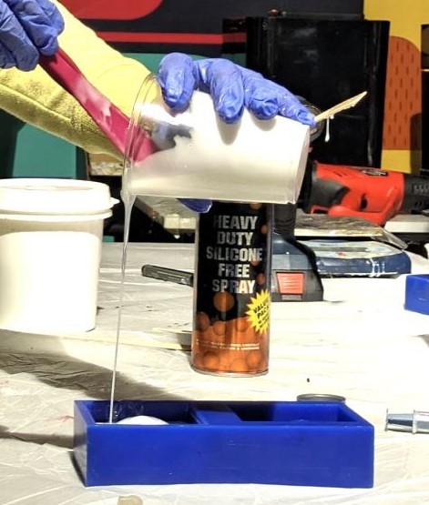
Poured in the mould
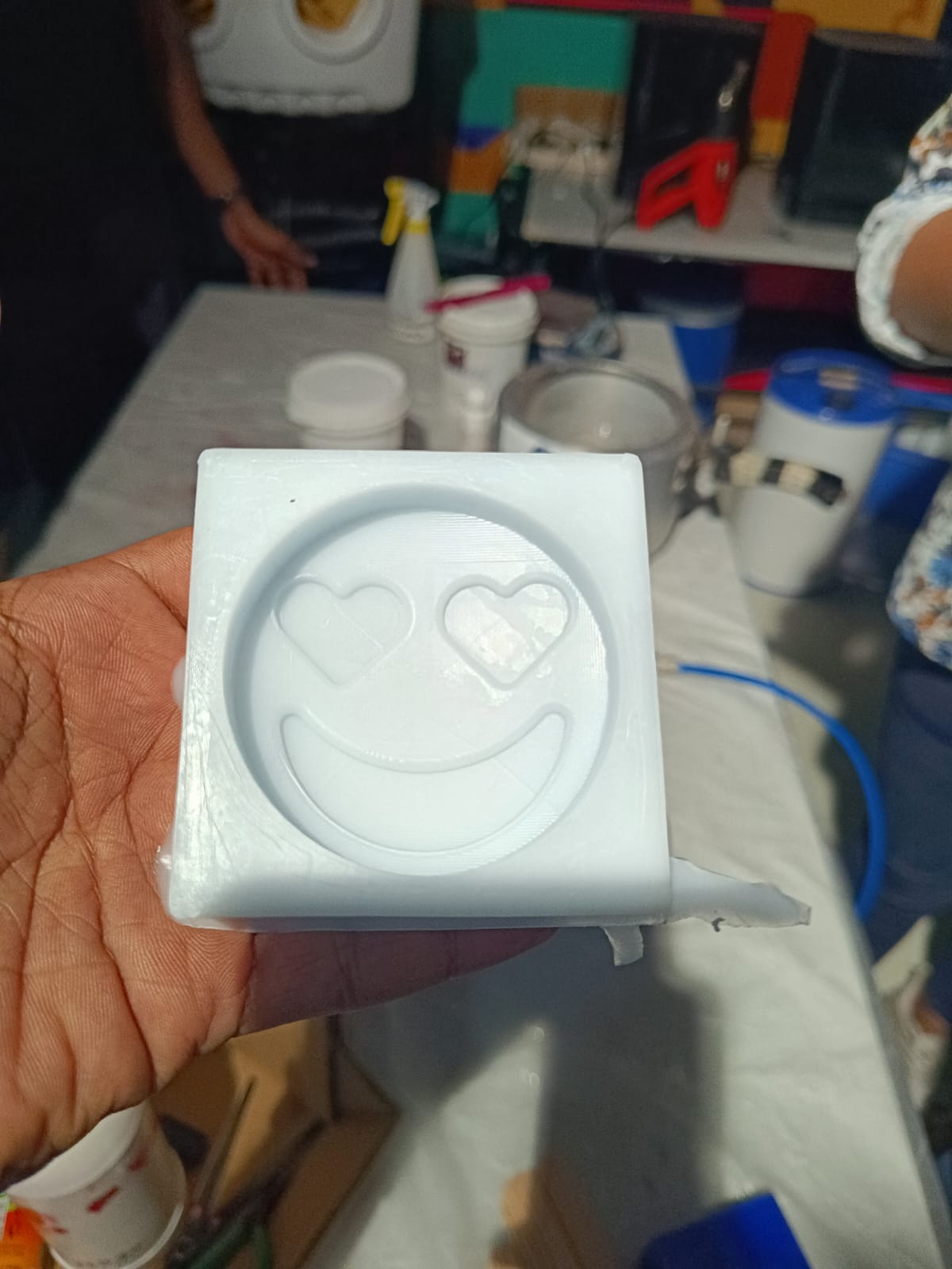
Next day once the mold had hardened, Look what i got
Casting
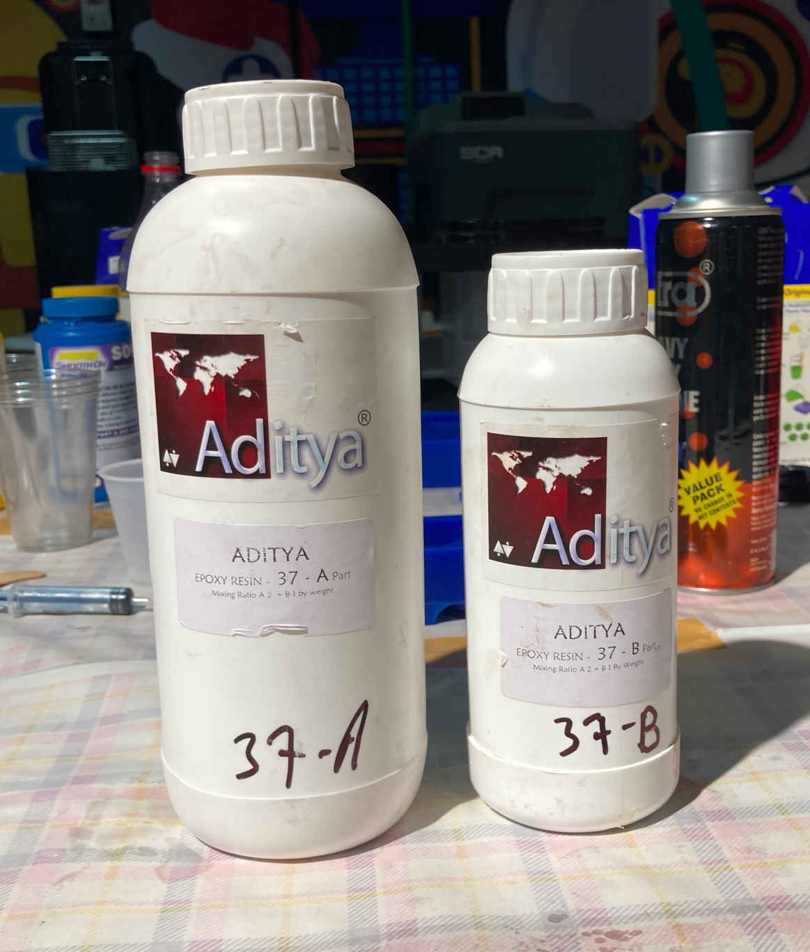
For Casting Resin we used Aditya Brand Resin. Which comes with 2 parts. Part A & Part B, which has a mixing ratio of 1:2.
Now we will measure the quantity by pouring water into the mould and passing the same to a transparent glass and mark down the measurement and weight.After getting the quantity we can mix the resin both parts to get the same quantity
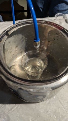
Degasing
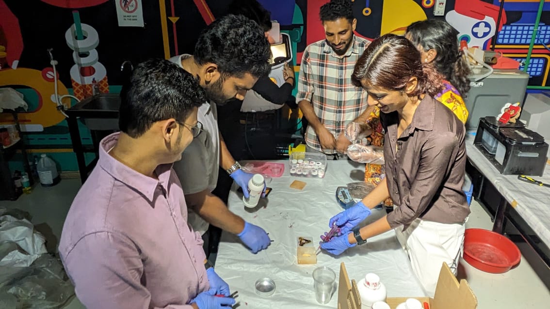
To remove air from the resin after mixing, I utilized an in-house built vacuum chamber.
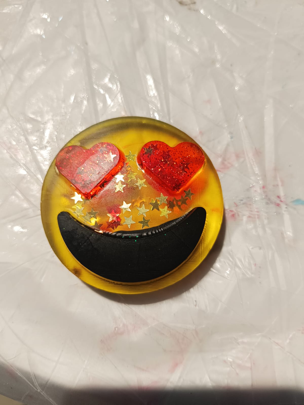
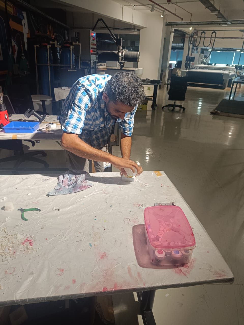
Once the air was removed, I poured the resin into the silicone mold. To enhance its appearance, I added some color and glitter to give it a cool and visually appealing look.
i Have mixed red colour for Eye and Black colour for Lips , then i have to wait 24 hr to mix the next colour (Yellow)
Waited for 12 hrs ,Then i mixed and poured yellow and finally,
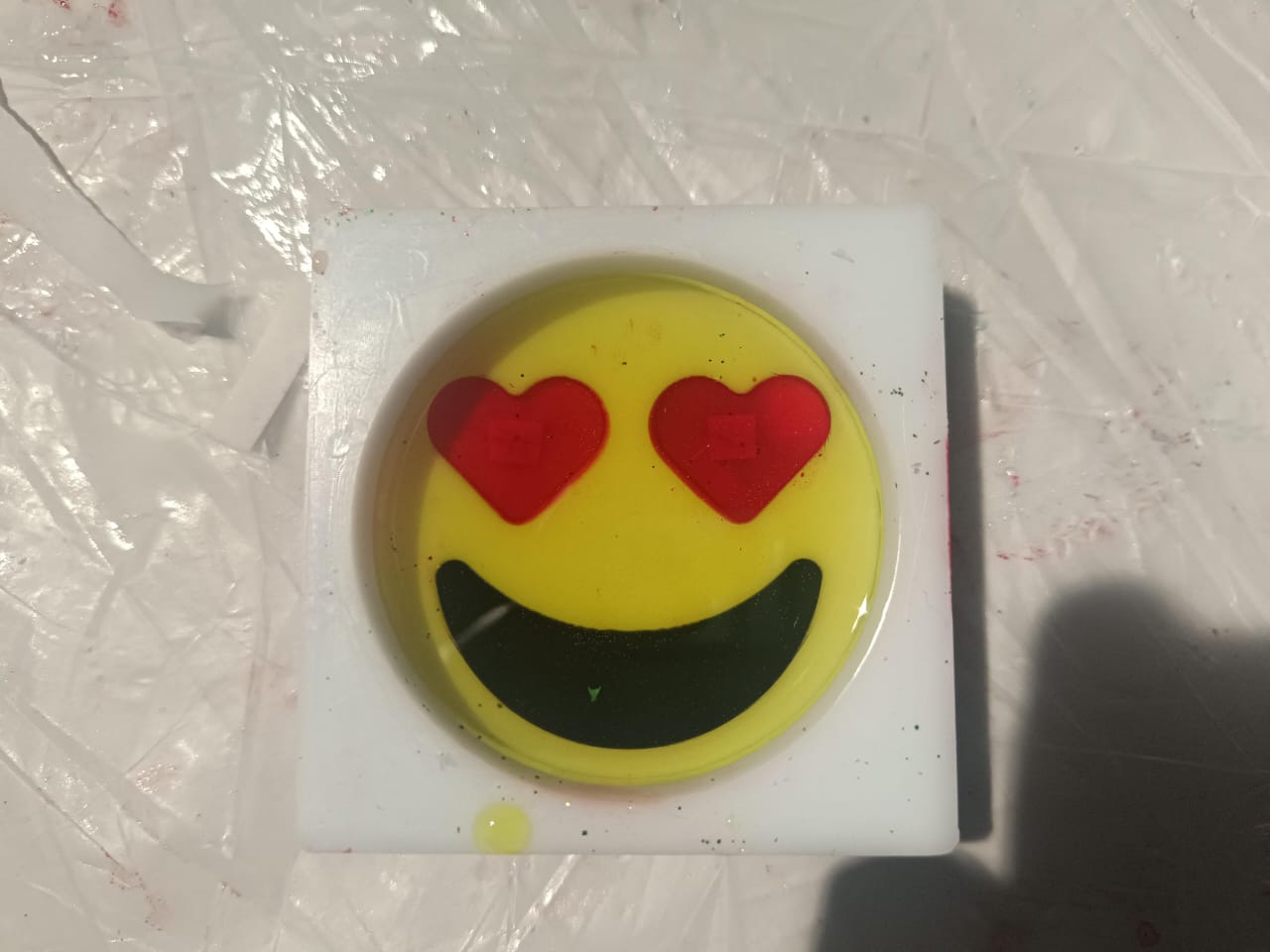
after 24 hours, i got this wonderful result