Applications and Implications
This week is the second-to-last week before the final projects are due for presentation. The goal of this assignment is to ensure thorough preparation for the final project by compiling a summary and addressing some crucial questions. This week's task involves answering the following questions:
- What will it do?
- Who's done what beforehand?
- What will you design?
- What materials and components will be used?
- Where will they come from?
- How much will they cost?
- What parts and systems will be made?
- What processes will be used?
- What questions need to be answered?
- How will it be evaluated?
What will it do?
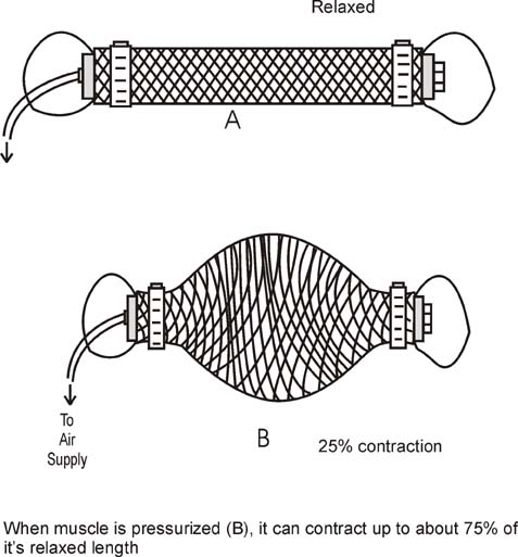
My artificial muscle should be a strength tester (force measurement) for a MCKibben Muscle. McKibben muscles, also known as pneumatic artificial muscles, mimic natural muscles using an inflatable bladder inside a braided mesh. When air is pumped into the bladder, it expands and the mesh contracts, generating movement and force. They are lightweight, flexible, and produce significant power, making them useful in robotics, prosthetics, and industrial automation.
For the testing I need:
- Frame
- Stepper Motor to adjust the tester for the length of the muscle
- Barometric Sensor for the air pressure inside the McKibben muscle
- A Load Cell for measuring the force
Who's done what beforehand?
There are several publications about the strength and testing of artificial muscles, but few provide detailed descriptions of building the tester. In this video demonstrates testing under various conditions: isotonic actuation, isometric actuation, actuation against a spring in series, and hysteresis in loading and unloading. In my setup, I aim to test isotonic actuation primarily, with the potential to implement isometric actuation as well, which isn't too difficult.
In the publication by Mayuko et al. 2009, they describe testing a muscle with a length of 700 mm and a force of 28 kN. However, the testing apparatus used for these measurements is not detailed.
In my lab, the artificial muscles produced consist of a balloon and a polyester sleeve. Additionally, connectors for the balloon and the tube are manufactured in-house, allowing me to use these ready-made components instead of creating my own muscles and connectors.
What will you design?
In my final project, I try to design and produce part myself. Most of the part I have already designed:
- Frame
- Electrical Box/Enclosure
- System Integration
- PCB
- GUI
A detailed description of my designs can be find on my final project page
.What materials and components will be used?
Fabrication Materials
| Amount | Material | Description | Link |
|---|---|---|---|
| 1 | PETG Filament | PETG White, 1,75 mm / 1000 g | HERE |
| 1 | ECOFLEX™ 0030/1 | - | HERE |
| 1 | Polyacetal Pom Sheet | 1mx2m Polyacetal Pom Sheet | HERE |
| 1 | PLA Filament | ecoPLA White, 1,75 mm / 1000 g | HERE |
Building Material
| Amount | Material | Description | Link |
|---|---|---|---|
| 1 | Trapezoidal threaded spindle | T10x2x2-550mm | HERE |
| 1 | Wood Plate | 24x32cm, Thickness 10mm | HERE |
| 2 | Trapezoidal threaded nut | T10x2x2 | HERE |
| 1 | Linear bearing | SCS10UU Linear bearing für 10mm Shaft | HERE |
| 3 | Deep groove ball bearing | Deep groove ball bearing 6200 2RS 10x30x9 mm | HERE |
| 1 | Alu Profile 8 40x40 | 2000mm; light; 4 sides open | HERE |
| 1 | Shaft rod | Cf53 Steel - 10 mm - length 510 mm | HERE |
| 1 | Timing belt | 1 meter GT2 timing belt open 10mm | HERE |
| 10 | Angle bracket | Angle bracket 40 x 40 groove 8 light with hammerhead screw fastening | HERE |
| 4 | Inner angle Angle connector | 20 x T Slot 90° L-shape T-slot Internal angle bracket Angle connector Aluminum profile T-Slot | HERE |
| 10 | T-Nuts with ball | M6/ M8 T-Slot Nuts 40 Series T-Slot Nut for aluminum profile extrusion slot | HERE |
| 20 | Socket head screws | socket head screws M6x20mm | HERE |
| 2 | wood screws | Multi-purpose screws, T-profile (for Torx) T10 | 3.0 x 20 mm | HERE |
| 4 | Threaded inserts | M3, internal thread metric knurled nuts assortment kit brass heat set insert | HERE |
| 8 | Pan head screws | PAN Head screws, cross recess, PZD, M3, 10mm | HERE |
Electronics Materials
| Amount | Material | Description | Link |
|---|---|---|---|
| 1 | Barometric Module | TC-10093132, up to 40 kPa pressure | HERE |
| 1 | Stepper Motor | NEMA 17, used in week 06 | HERE |
| 1 | Motor Driver | a4988, used in week 06 | HERE |
| 1 | Load Cell | RB-Phi-120, Tension Micro Load Cell (up to 50 kg) | HERE |
| 1 | Load Cell Amplifier | HX 711 | HERE |
| 1 | Power Supply | 24V power supply unit 1.5A plug-in power supply unit | HERE |
Where will they come from?
The material can be ordered from the links in the table. Some of the material are underlined as they are already in stock in the lab.
How much will they cost?
The materials that were in stock are not listed in the costs.
| Amount | Material | Price in EUR |
|---|---|---|
| 1 | PETG Filamen | 29.99 |
| 1 | ECOFLEX™ 0030/1 | 38.81 |
| 1 | PLA Filament | 19.99 |
| 1 | Trapezoidal threaded spindle | 12.55 |
| 1 | Trapezoidal threaded nut | 5.43 |
| 1 | Linear bearing | 2.99 |
| 3 | Deep groove ball bearing | 3.26 |
| 1 | Alu Profile 8 40x40 | 49.60 |
| 1 | Shaft rod | 7.14 |
| 1 | Timing belt | 2.75 |
| 10 | Angle bracket | 2.28 |
| 4 | Inner angle Angle connector | 12.69 |
| 20 | T-Nuts with ball | 16.99 |
| 1 | Barometric Module | 8.99 |
| 1 | Load Cell | 9.17 |
| 1 | HX-711 | 14.70 |
| 1 | Power Supply | 15.99 |
| IN TOTAL | 280.36 |
What parts and systems will be made and how will they produced?
For the parts not manufactured or manipulated in any other way (saw), the description of the material can be found in the Bill of Materials.
| Part | Manufacturing Technique, Material |
|---|---|
| Frame | Manually Cutted Profile and screwed together |
| Enclosure/Electrical Box | Laser Cutting, POM |
| Wood | cut with a saw |
| 4 Feet for the box | 3D Printed, PLA |
| Enclosure Barometric Sensor | 3D Printed, PLA |
| Enclosure HX-711 | 3D Printed, PLA |
| PCB Holder | 3D Printed, PLA |
| Linear Motion System | 3D Printed, PETG , saw for the shafts |
| Mold for Barometer connection | 3D Printed, PLA |
| Cable connections | 3D Printed, PLA |
| Barometer connection | ECOFLEX, Molding and Casting |
What questions need to be answered?
Right now, I am more or less done with the project. A huge part is the application programming, to much movement of the linear motion system in z-direction, and some problems with the barometric sensor.
How do I want the output to be generated and processed? How should the measurements be visualized?
The Python program needs to be expanded to enhance its functionality. After mounting the artificial muscle into the frame, an initial measurement should be taken. This is to ensure that the muscle is neither contracted nor applying excessive force to the load cell. This preliminary step is crucial to establish a baseline and ensure accurate measurements during the experiment.
Furthermore, the Python program should be equipped with controls to start and stop the measurement process as needed. This functionality will allow for precise control over the data collection process. Once the measurement is stopped, the program should be capable of processing the recorded data and generating a graph that visually represents the values obtained during the measurement.
By implementing these features, the expanded Python program will significantly improve the ease and accuracy of testing artificial muscles, providing valuable insights into their performance characteristics.
How can I stop the movement of the z-leveling?
The movement of the Z-leveling mechanism is due to excessive tolerance in the 3D-printed parts that interface with the central profile. To resolve this issue, the parts should be reprinted with reduced tolerance. Additionally, screw holes should be incorporated into the design, allowing the 3D-printed parts to be securely mounted to the profile using screws and nuts. This will enhance stability and ensure precise Z-leveling.
How can I solve the problems with the barometric pressure sensor?
The issue with the sensor is that although it is designed to measure up to 40 kPa, the analog output reaches the maximum 5V at only 8 kPa. This discrepancy could be due to counterfeit components. Since I was unable to resolve the problem, I have ordered a new sensor. If the issue persists with the new sensor, I will proceed with the experiments and measurements using a maximum of 8 kPa. It is likely that the new sensor will have the same problem, as some reviews indicate this is a common issue.
How will it be evaluated?
The final project should integrates the range of units covered and incorporate according the requirements of FabAcademy:
- 2D and 3D design
- Additive and subtractive fabrication processes
- Electronics design and production
- Embedded microcontroller interfacing and programming
- System integration and packaging
- Lastly, all parts of the final project should be made rather than bought, if possible.
These are the requirement I defined myself, to make sure my project works:
- The output and input devices are properly connected, ensuring that their output can be accurately processed to translate into correct values. These values should be effectively visualized in a graph, providing clear insights into the system's performance.
- All electronic components, except for the load cell, are concealed within the machine's housing. This ensures a tidy and professional appearance while minimizing the risk of damage or interference.
- The machine is equipped with convenient connectivity options, allowing for easy connection to a computer. This facilitates data transfer, analysis, and control, enhancing the machine's usability and versatility.
- The frame of the machine is robust and structurally sound, capable of withstanding the forces exerted during operation. This ensures stability and safety during use, preventing any structural failures or hazards.
- The machine incorporates user-friendly controls and interfaces, enabling intuitive operation and adjustment of settings. This enhances usability and accessibility for operators, minimizing the need for specialized training or expertise.
- The machine is designed with modularity and scalability in mind, allowing for future upgrades or expansions to accommodate evolving requirements or additional functionalities.