3D Printing and Scanning
Assignments
- Group Assignment
- Test the design rules for your 3D printer(s)
- Individual Assignment
- 3D scan an object
- Design and 3D print an object (small, few cm3, limited by printer time) that could not be made subtractively
- Explain what you learned from testing the 3D Printer
- Include the design files
Hero Shots
3D Scanning
For 3D Scanning we used the EinScan-Pro+ from Shining 3D. Unfortunately, the company is not very open about the technology, that lies behind this, but in general, the two (observed) principles behind it are Structured Light Scanning and Stereocamera system. Structured Light Scanning projects a pattern of light onto the object and uses a camera to capture the deformation of the pattern on the object's surface (center of the device). Stereocamera-based 3D scanning, also known as stereophotogrammetry, involves using two or more cameras to capture images of an object from different viewpoints. As these cameras are monochrome, a camera with color vision is additionally mounted on top of device. By analyzing the disparities between corresponding points in these images, the system can determine the depth information and reconstruct a 3D model.
Setup
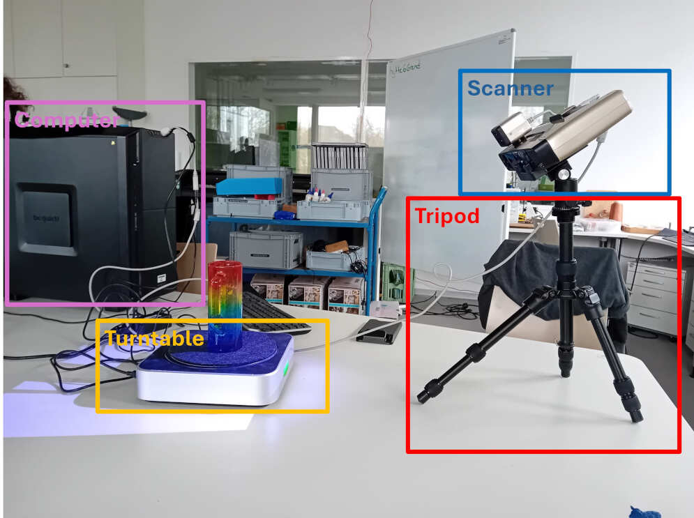
The EinScan-Pro+ package comprises a 3D scanner, a precision turntable, a calibration board, and a stable tripod. The scanner, known for its advanced technology, facilitates detailed and versatile 3D scanning. The accompanying turntable ensures controlled object rotation, contributing to overall scanning accuracy. Integrated with the "EinScan Pro Series" software on a lab computer, the system provides an interface for scan management and settings adjustment. To initiate a "fixed" scan, the 3D scanner is securely affixed to a tripod and positioned approximately 30 cm from the turntable. For "free" scans the 3D scanner can be moved and rotated around the object manually with th e integrated handle.
Control and Scan
The scanning process is meticulously managed within the software (on the computer), involving careful preparation, execution, and conclusion. To initiate a scan the right scanner needs to be selected. Thereafter, the calibration of the scanner is initiated.
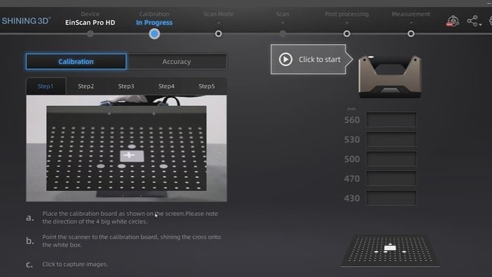
The initial five steps of calibration are dedicated to position and angle calibration. This entails adjusting the position angle of the calibration board and modifying the distance by manually raising and lowering the 3D scanner.

Additionally, a calibration of the brightness is done by calculating the brightness of the white spots on the calibrating board. To enable a good resolution and quality of the scan it is crucial to keep the brightness constant in during the calibration and the scan.
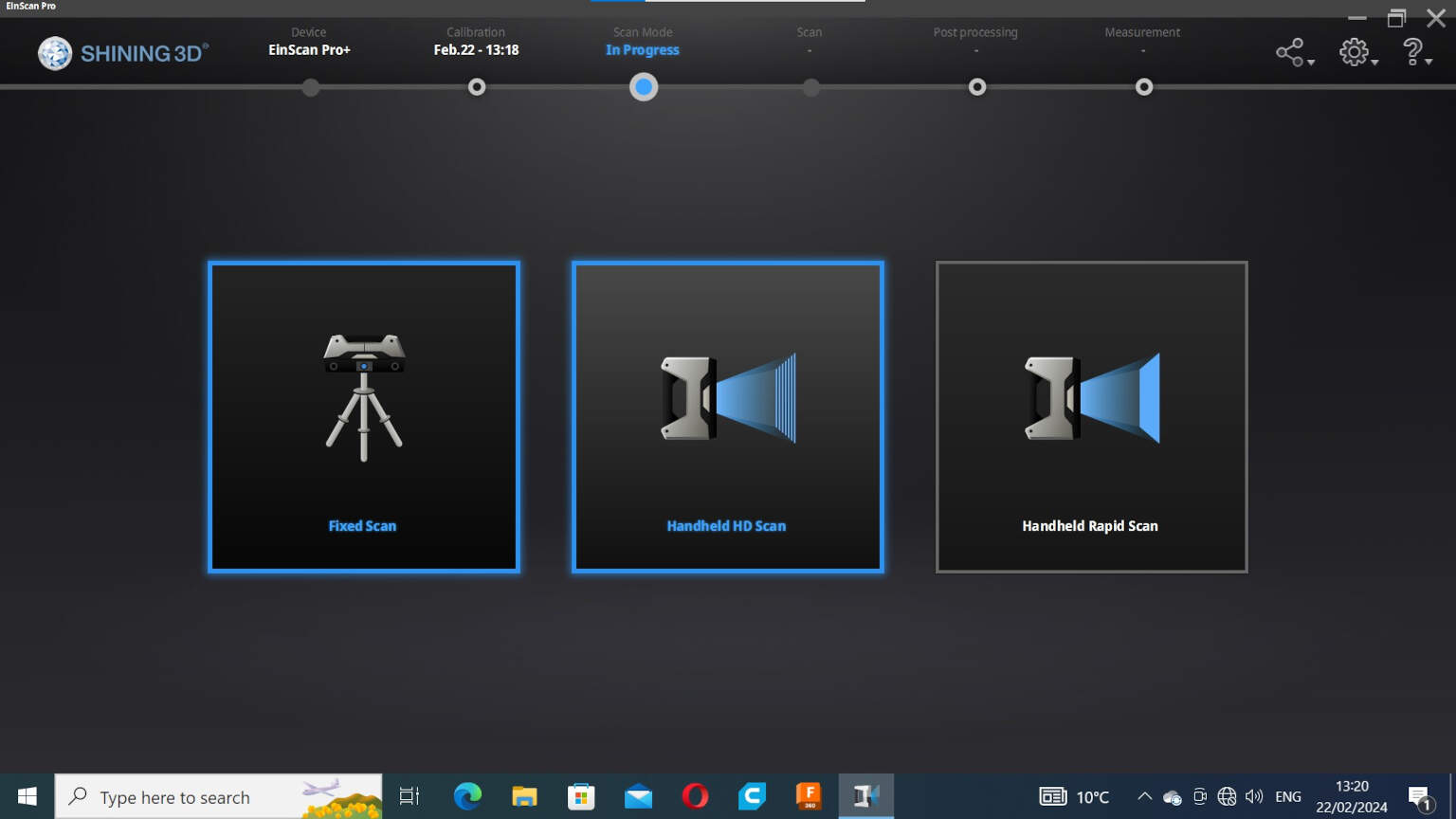
The next step is to select he type of scan. For the chosen object (small figure of a sheep), the fixed scan was the right choice (it includes mounting the camera to the tripod and using the turntable). After clicking on "fixed scan" the software will give the option to choose to create a new file or use an existing one. Click on the needed option for your work.
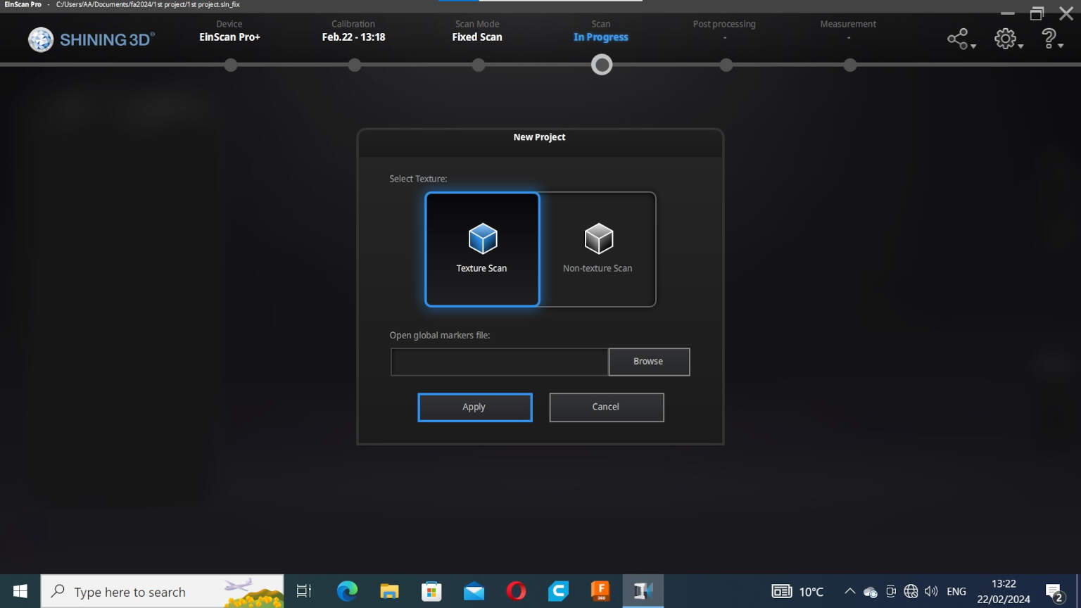
Depending on the application there is the option to choose textured or non textured scan. For the application I used textured scam. Thereafter, you can browse for the repository you want the scan to be captured and saved in. Choose a repository and click on "Apply".
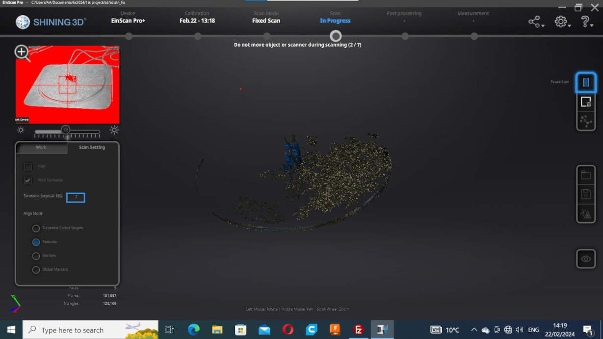
After clicking "Apply", the scanning settings can be adjusted. Here, I selected "With Turntable" with initially 7 steps and "Features" for the align mode. In this mode, it recognizes features like the shape and texture to align multiple scans to a single point cloud. The brightness needs adjustment depending on the color of the object. As direct feedback of the brightness adjustment it is useful to look to the screen above the setting window. The brightness should be adjusted in a way, that only the object is in a red color and not the surrounding elements.
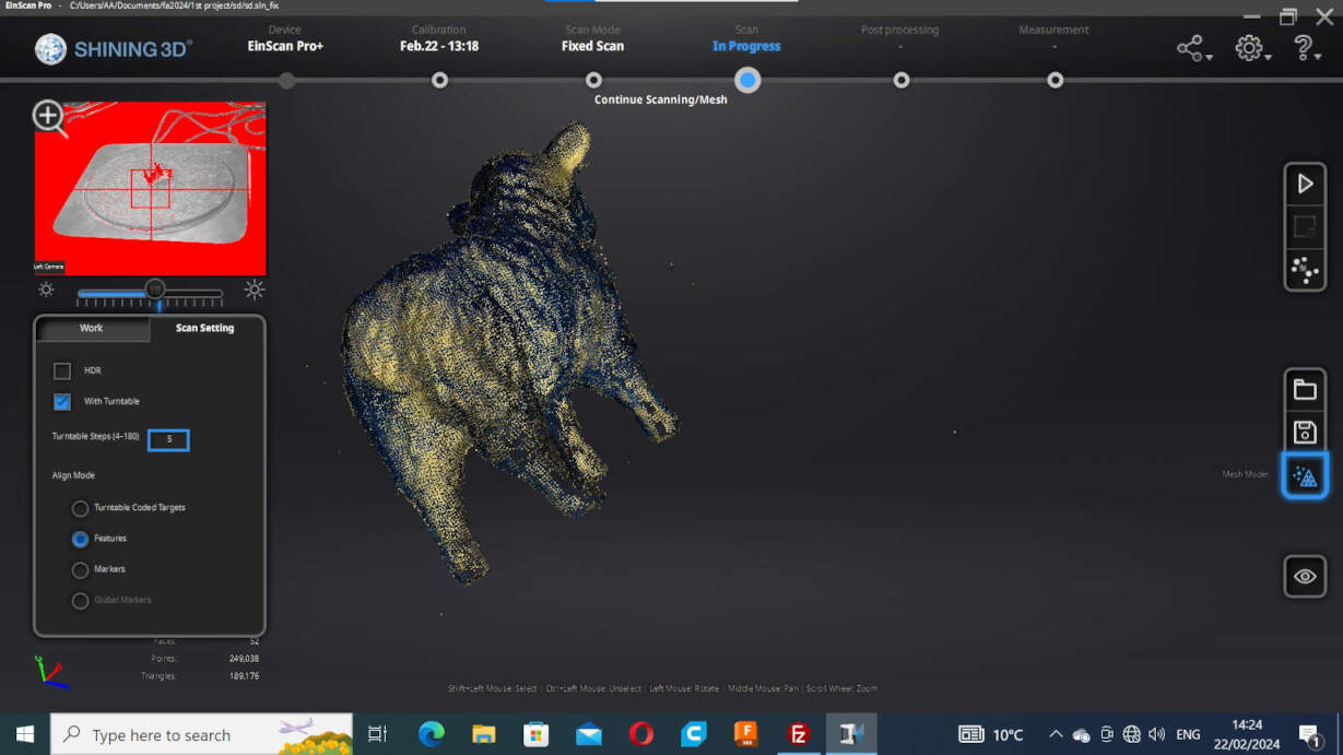
To improve mesh quality and resolution, three scans were conducted for the object in question. Between each scan, mesh manipulation was performed using the "mesh model" feature. This facilitated the removal of unnecessary points and the identification of missing parts within the mesh. For enhanced coverage, the "turning steps" were varied by a few steps during scanning to capture missing details more effectively. Additionally, the object was scanned in different positions, such as laying it down for the sheep to capture intricate details, especially in the belly area.
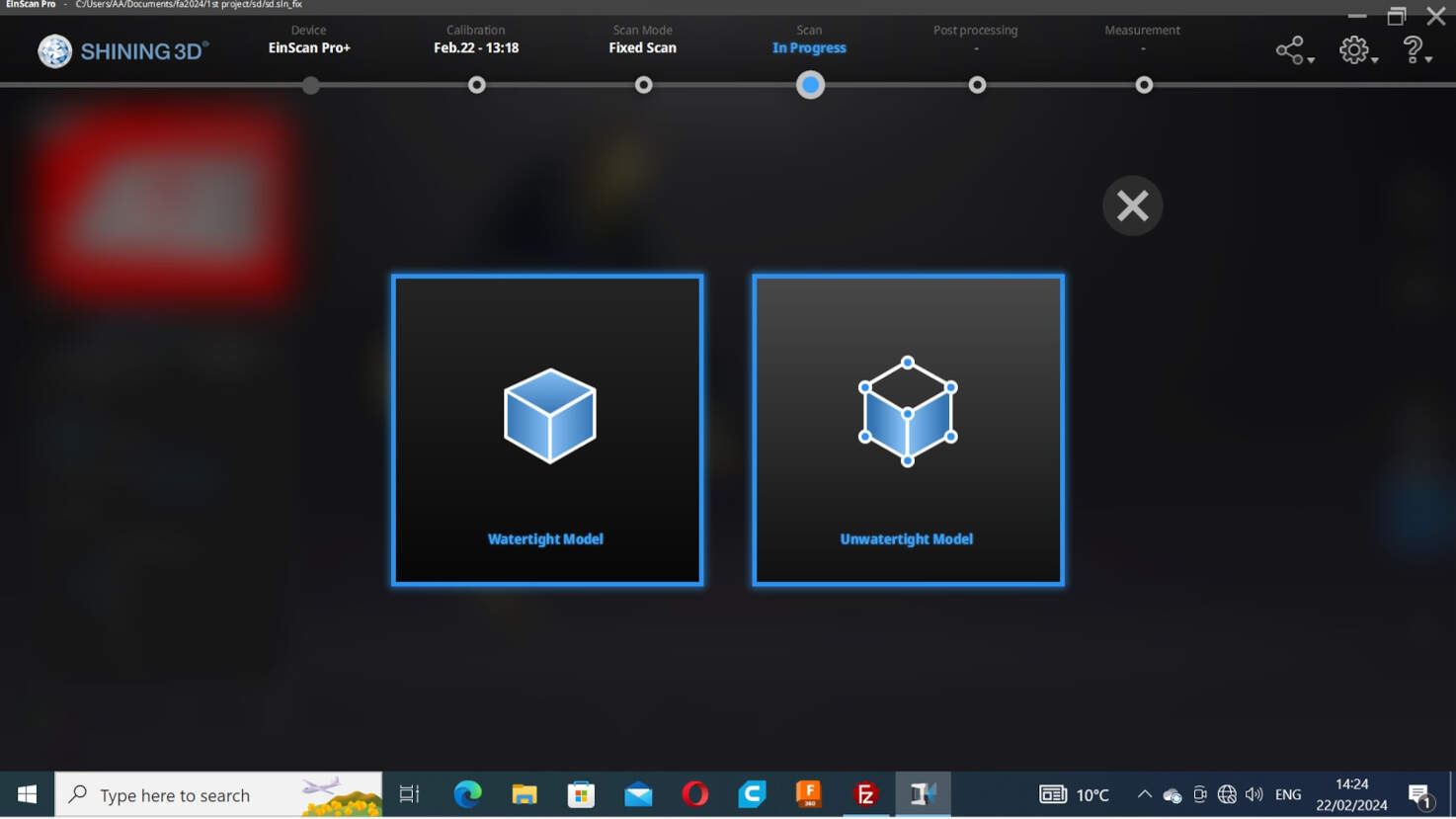
Following the scanning process, the next crucial step involves determining the mesh quality. The choice between a watertight and unwatertight model is presented, and, for the sheep project, I opted for a watertight model. Subsequently, the decision for the mesh quality was made in favor of high detail. The system is now in the process of calculating the model, and this operation requires some time.
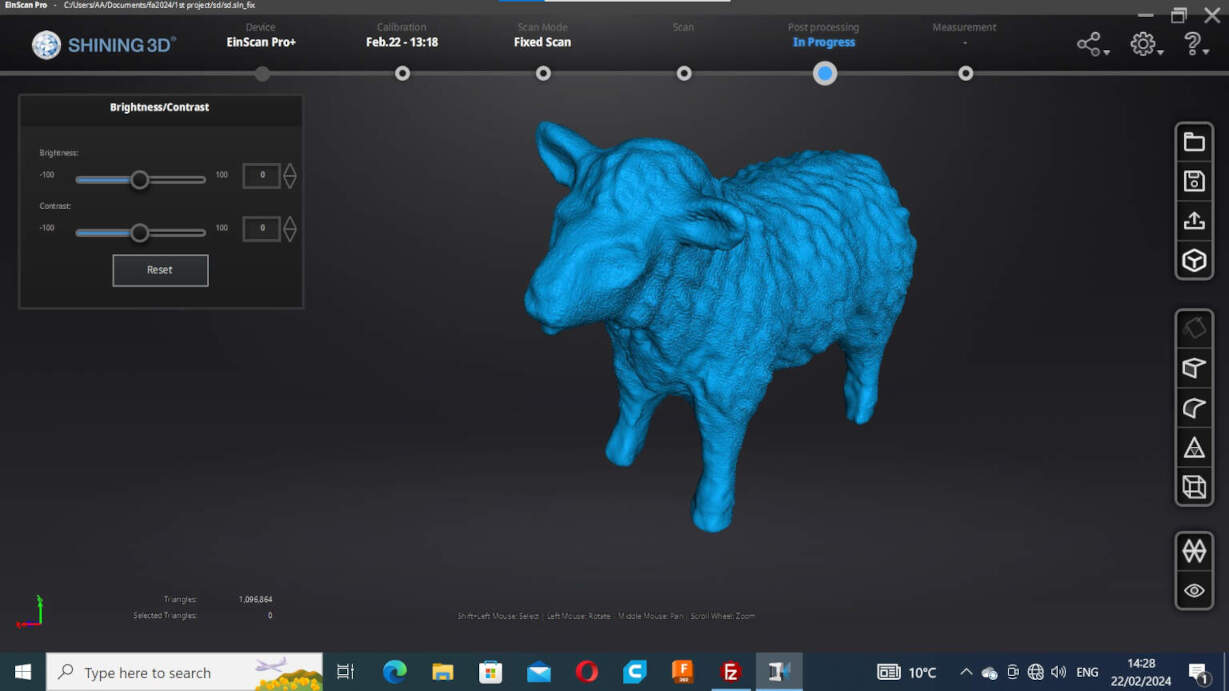
In the last step, the texture and color can be changed slightly, as well as the size. After this the software fives several options for output files. To not loose any information I decided, to create all existing possible output files.
Post Processing and Designing
When preparing the design for printing, mesh simplification became imperative due to issues with Cura's processing capacity, leading to software shutdowns. Blender was chosen for this task, despite some ambivalence. Having used Blender extensively years ago, revisiting the software revealed significant changes in both functionalities and the user interface.
Blender, renowned for its mastery of shortcuts, poses a learning curve, especially for users accustomed to different software interfaces. While the depth of Blender's capabilities is appreciated, adapting to its unique shortcuts demands an investment in time for intuitive usage.
Acknowledging both the strengths and challenges of Blender, the decision to utilize it for mesh simplification was made. Despite the learning curve, Blender's robust features and capabilities, especially in mesh manipulation, make it a valuable tool for optimizing 3D models for printing.
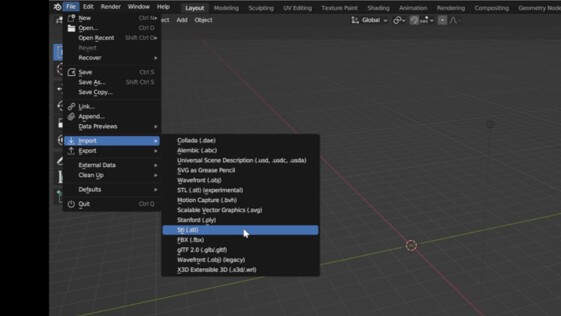
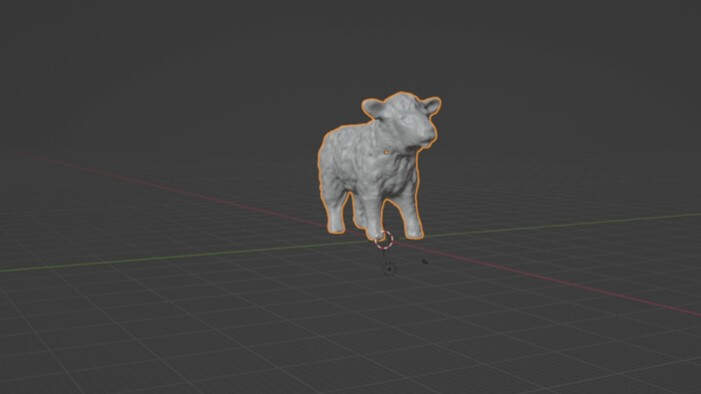
To start the manipulation in blender import one of the provided scan files (I used the .stl file).
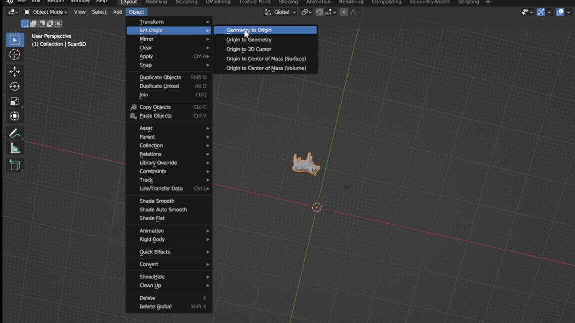
The model was some were in the workspace far away from the origin. To align the model with the origin, go to "Object", "Set Origin", and click on "Geometry to Origin".
To refine the position, press "left mouse + y,x,z" to fix the translatory alignment with the axis and "r + y,x,z" for rotatory alignment with the axis. To have a look around your object use the numpad to change the direction and to switch between orthographic and perspective projection.
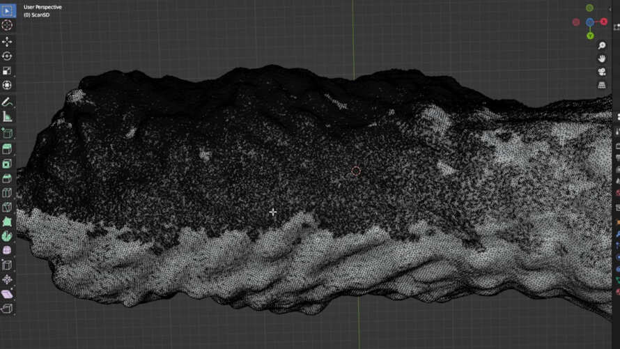
By pressing "Tab" you can switch between object and edit mode. In the edit mode the faces, edges and vertices of the object are visible and edible. By looking at the mesh it is noticeable, that the mesh is irregular. One side of the sheep consists of more faces. The reason for this is the placement of the sheep on the turntable on side.
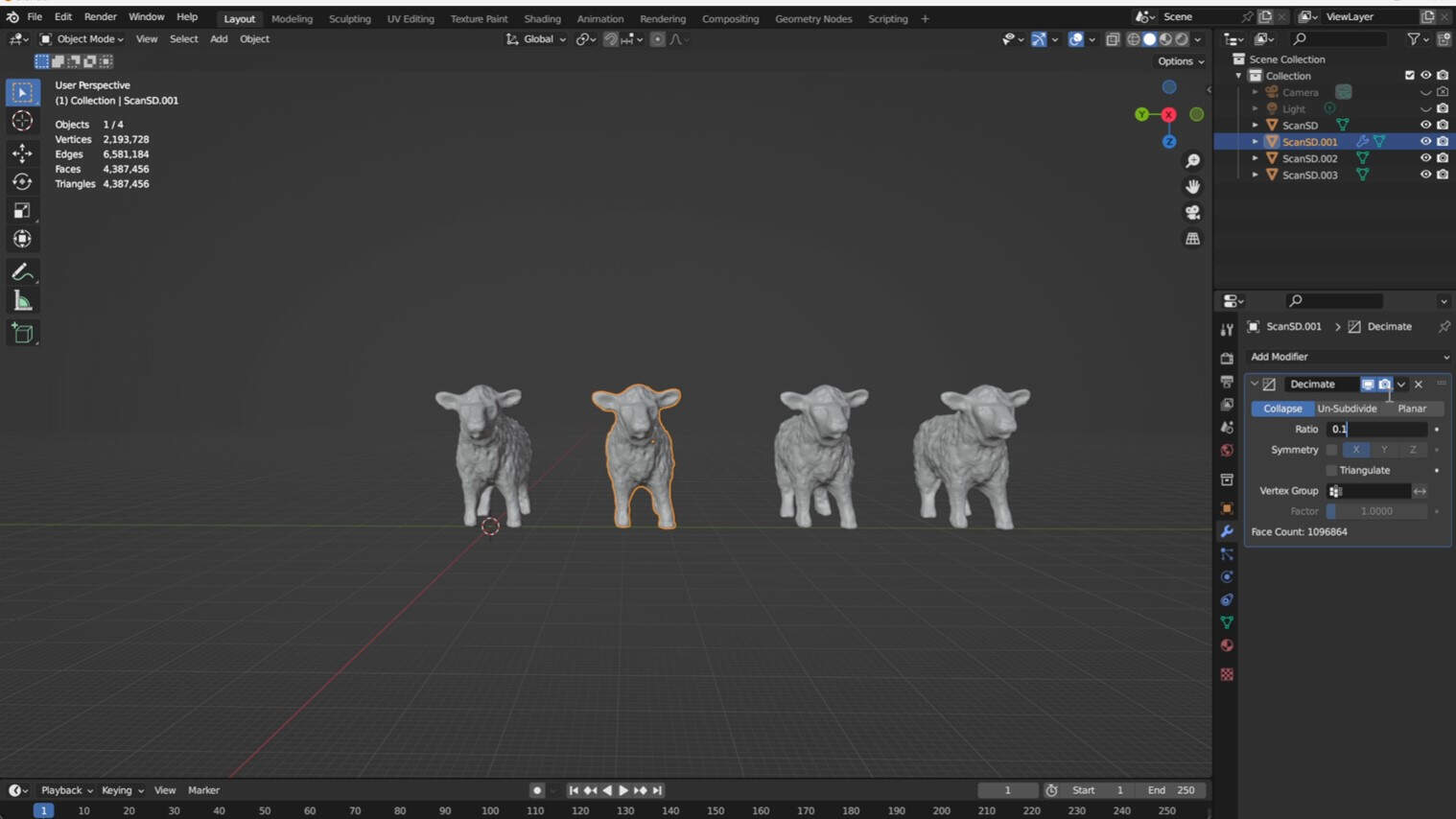
Press "shift + D + y,x,z" to copy the object and move it along the axis. Open the modifier menu (wrench symbol, right side) and add the "decimate" modifier. To decimate the faces to 10% of the original one, you use a ratio of 0.1. To apply the modifier to your object select the object and press "ctrl + A".
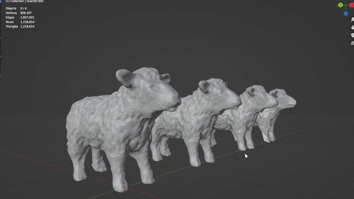
I decimate the complexity t0 10 % , 1%, and 0.1 % to see the difference between the different decimation. In my opinion the best option to go for the print is 10 %.
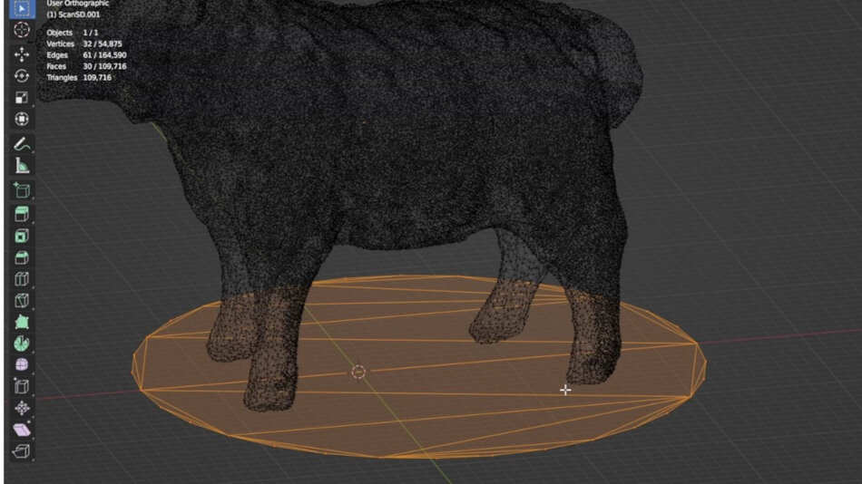
I decided to create a pedestal for the sheep. I started to create a circle (press Shift + A and select the circle) and then I scaled it the a fitting size (press S) I then moved the circle to be aligned centrally with the sheep (press G + x,y,z).
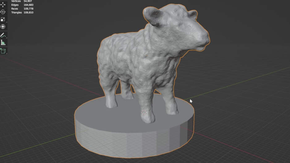
The last step was extruding the circle in z direction (press E + z). Then I went back to object mode (press Tab) to see the final result.
Photogrammetry
Additionally, to the EinScan technology I decided to try Photogrammetry. Photogrammetry is a technique used to create 3D models of objects or scenes by analyzing photographs taken from different viewpoints. The process involves capturing a series of overlapping images of the subject from various angles, and then using specialized software to extract 3D information from these photographs.
Setup and Control
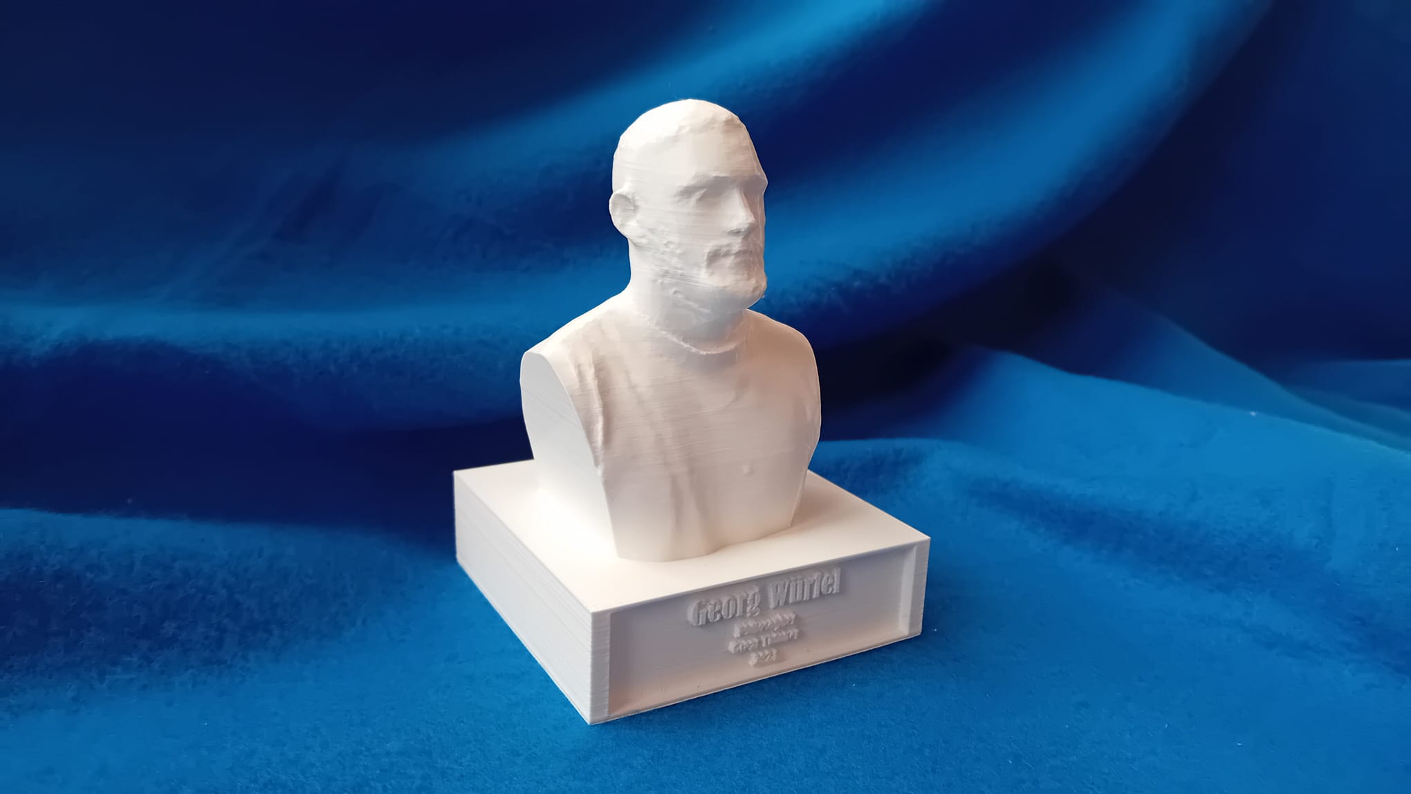
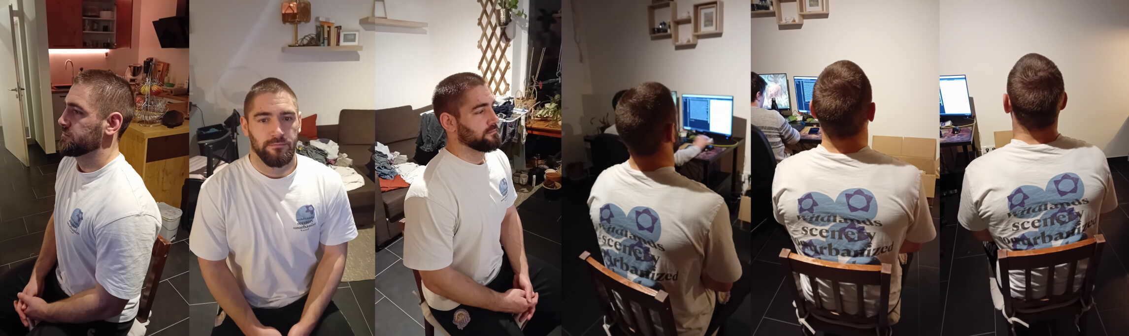
When embarking on a photogrammetry project, the initial decision involves choosing between scanning a single object or capturing an entire scene. In my case, I opted to scan a singular subject: my friend Jure Cubelic, a person I consider to be the epitome of intelligence, sophistication, wisdom, humility, and eloquence. Therefore, it was obvious that the future generations need a 3D model and bust of him. ;)
For this task, all that's required is a camera and ample space. Position the chosen person or object in the center of a room, and systematically capture photos from all angles. It's crucial to maintain a consistent distance between the camera and the subject, ensuring uniformity, and to control the lighting conditions for optimal results.
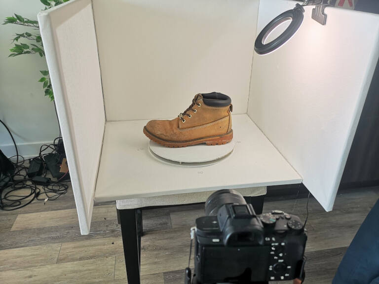
The goal is to create a comprehensive set of images that captures the subject from every perspective. This meticulous approach lays the foundation for a successful photogrammetry process, ultimately transforming the images into a detailed and accurate 3D model.
The quality depends on several things and can be improved further by a better camera and by creating a setup, where the distance from the object can be kept constant and the object is kept on a turntable.
I utilized my Samsung A14 mobile phone to capture images of Jure. Placing him on a chair, I took photos from approximately the same distance to ensure consistency in the data collection process.
Software
Meshroom
The first software I tried was Meshroom, Which is an open-source software from AliceVision . The
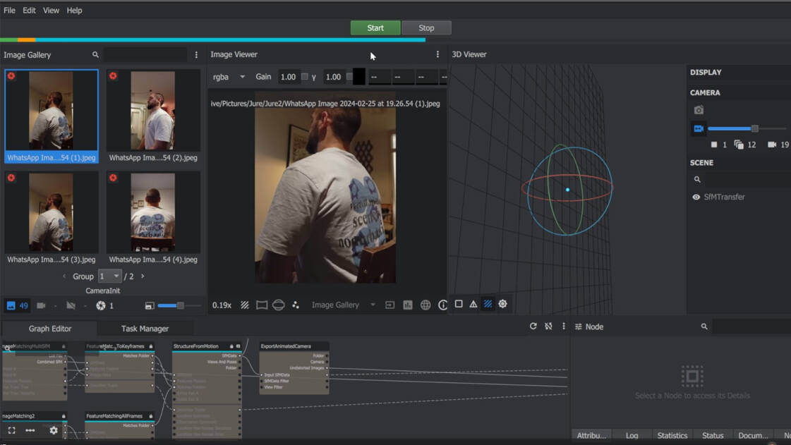
The Meshroom Interface is pretty intuitively. The pictures can be drag and dropped into the image frame. After that you can just press start.
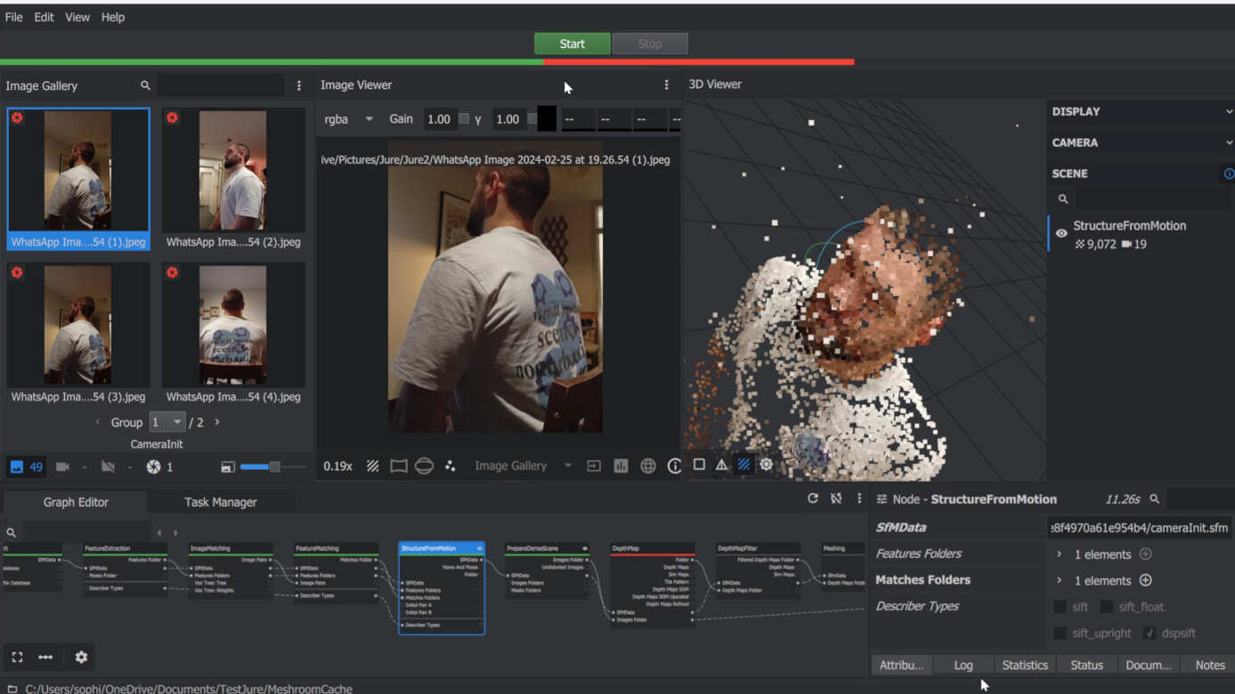
After that you can first see the structure of points created from the photos. Unfortunetly, after creating the points (step StructurefromMotion) the further processing was not working out. The main reason for this is the missing back of the points. Somehow the software excluded many photos from creating the mesh.
I suspected that the unsuccessful meshing could be attributed to the insufficient number of pictures and variations in brightness. In response, we generated a second set of images, making an effort to enhance coverage. During this attempt, only the back of Jure was successfully meshed into points. Unfortunately, similar challenges persisted, hindering further meshing. Given these limitations, I opted to explore an alternative software solution to address the issues encountered during the meshing process.
Polycam
The next software is a online software for photogrammetry Polycam.
The software is pretty easy to use.
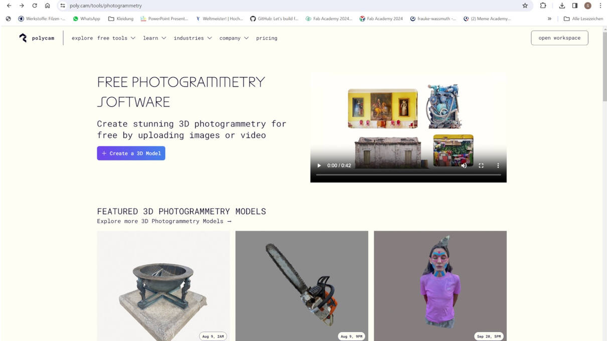
CClick on 'Create 3D Model,' then simply drag and drop your images into the prompted window. Choose your desired quality settings and initiate the process by clicking "Start".
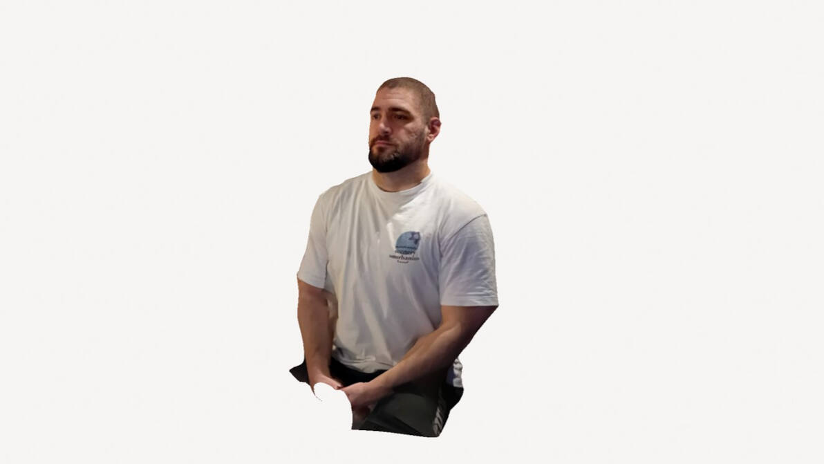
Following that, Polycam processes your mesh and presents you with the reconstructed 3D model derived from the photos.
In my opinion, the results of Polycam were quite good. If you do not buy the pro version of the software, the model can only be exported as 3D model as a .glb file.
Postprocessing of the Mesh
The file type can be imported in Blender to further process the model to make a Jure bust out of the mesh. To create the bust follow these step.
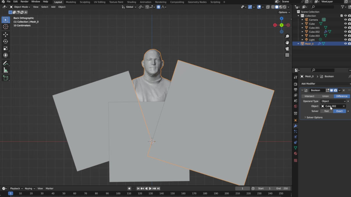
"I imported the model and introduced three cubes by pressing Shift + A and selecting 'Cube.' To achieve the desired shape for the bust, I employed the 'Boolean' modifier, carefully adjusting and refining the model.
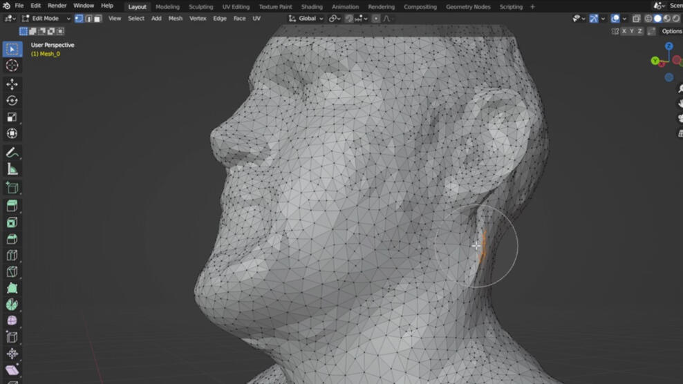
Subsequently, I switched to edit mode and addressed the rough areas of the mesh. To refine the selection of specific areas, I utilized the visual mesh manipulation tools located in the right upper corner (circles). The circled selection tool, activated by pressing 'C', proved particularly helpful in achieving precise edits.
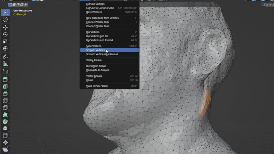
To smooth the vertices, go to "Vertices" and click on "Smooth vertices". A menu will pop up in the right bottom corner, play with the parameters to find the right smoothing factor.
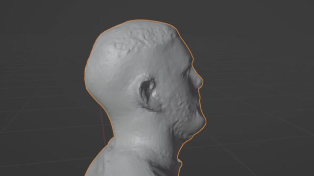
After completing the smoothing process, I verified the mesh's closure and assessed the natural appearance of the applied smoothing.
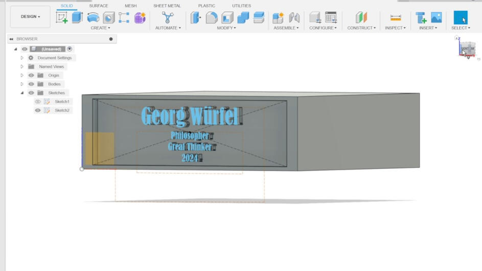
I created the pedestal for the bust in Fusion 360. Any further information on designing something in Susion can be found in the documentation of week 2.
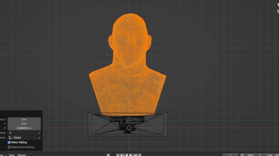
I imported the pedestal into Blender and positioned (G + x,y,z) and sized (S) it the right way.
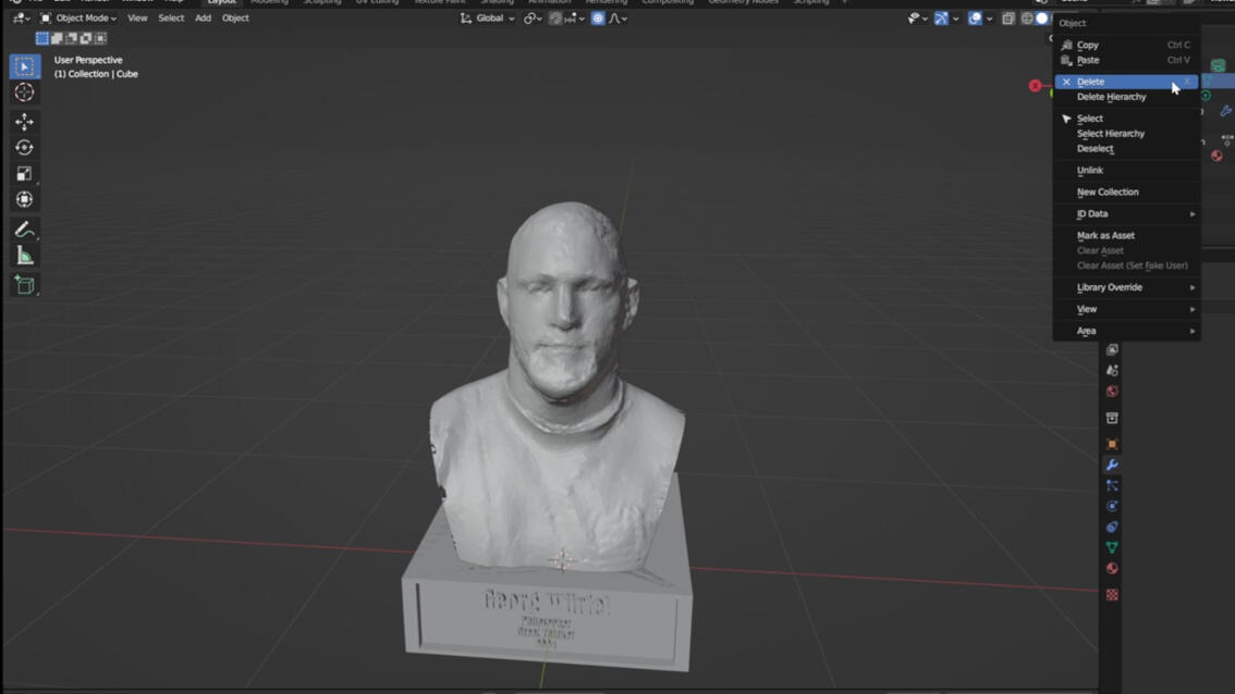
Subsequently, I employed the boolean modifier once more, opting for the union option to seamlessly combine the bust and the pedestal into a single object. Furthermore, I removed the cubes from the model. After these adjustments, I exported the finalized model as an .stl file for integration into Cura.
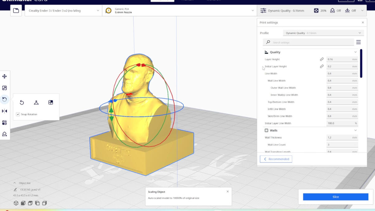
The final step involved importing the file into Cura to assess whether the mesh is closed and if the subsequent print would meet expectations. Simply click on 'Slice' and then proceed to 'Preview.' If the mesh is not closed, you'll observe missing layers in the preview, which may translate into issues during the actual print..
3D Printing
In this assignment the most exciting part was 3D printing. :)
Setup
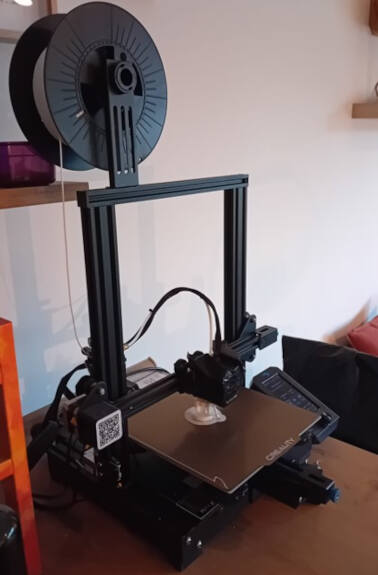
The setup and types of printers we used in this week can be found on the group page (see here). As I used my own 3D printer for the prints at home as it was more convenient, I will describe my setup and printer in this section.
The printer I am using is the Ender 3 v2. The important parts to start a print are: the printer, filament (PLA), and an SD card, to import .gcode from a slicer on your computer to the printer. Key components of the printer include the print bed, where 3D prints materialize, the printing head responsible for layer-by-layer filament extrusion and material cooling (fan), and the 3-axis movement system for precise control. Filament, typically PLA, is loaded onto the printer (filament holder) and threaded to the extruder. The printer is equipped with tools like a spatula for easy object removal and pliers for support removal.
Control
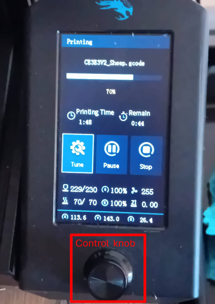
To manually control the printer and start a print, use the interface with the control knob:
- The control knob can be moved clockwise and counter-clockwise.
- Press down to confirm a selected option.
The interface provides the following options:
- Print: Choose a print file if an SD card is inserted. Initiate, pause, or stop a print during the process.
- Control: Manually move the printer head along all three axes.
- Prepare: Manually adjust nozzle and bed temperature, and configure the speed of the printer head.
- Info: Access detailed information about the printer, including specifications and status.
3D Printing
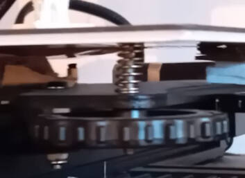
Ensuring optimal print quality with the Ender 3 necessitates periodic bed leveling calibration. Follow these steps:
- Manually position the nozzle at a height of 0.0 (z = 0.0) by traversing it to each corner of the bed.
- Employ a piece of paper to assess the distance between the nozzle and the bed. The correct height allows the paper to move under the nozzle with slight resistance.
- Utilize the wheels located under each corner of the bed to make height adjustments. This ensures precise leveling and promotes consistent layer adhesion during prints.
When it's time to change the filament, follow these steps:
- Turn on the printer and navigate to "Temperature" -> "Nozzle" in the "Control" menu. Set the temperature to around 200°C for PLA.
- Once the set temperature is reached, squeeze the extruder lever to release the filament gently. Pull out the filament; you'll notice the melted end, facilitating easy removal from the extruder.
- Choose the new filament and mount the spool onto the spool holder. Hold down the extruder clip, pass the filament through, and continue through the bowden tube until you feel resistance.
- The filament is now at the nozzle, but there's residual filament from earlier. To purge the old filament, use the "Change Filament" option under "Prepare" -> "Change Filament."
3D Printer Parameter Testing
All the test are described in detail in the group assignments page (see here). This chapter is dedicated to, what can be learned from these tests and the important point. The printers produced quite some different results in all of the tests. The tests reinforced what I had already learned over my time:
- Design Stage:
- Before designing a part, think about the type of production you want to use and adapt your design to the production
- Try to avoid overhangs and support (it leads to a decrease in quality and increase of production time)
- Think about the forces the product has to deal with (3D Printing is Anisotropic)
- Ensure that the size of features, such as holes and details, is within the printer's resolution capabilities
- Consider the nozzle diameter and layer height when designing fine details
- Ensure sufficient clearance between moving parts and consider the effects of material shrinkage.
- Understand the properties of the 3D printing material you plan to use (e.g., PLA, ABS, PETG, Nylon).
- Design walls with adequate thickness to ensure structural integrity
- Slicer:
- Design parts with a flat base for better adhesion to the print bed.
- Consider using a brim or raft for added stability, especially for larger parts.
- Adjust print speed and layer height settings based on the desired balance between print quality and speed. (Higher layer heights may result in faster prints but lower surface quality)
- Find the working slicer parameters for your specific 3D printer and material and stick with it. (Every printer (sometimes even if it is the same model) has their specific parameters settings)
- Adjust your shell thickness and infill density to your needs
- Printing:
- Ensure that your 3D printer is properly calibrated. Check bed leveling, nozzle height, and other settings to avoid issues with adhesion and print quality.
- The environment of the printer influences the print (vibration, moisture, temperature, etc.)
Designing
As a special request after the local evaluation, I decided to include another design to print. ;)
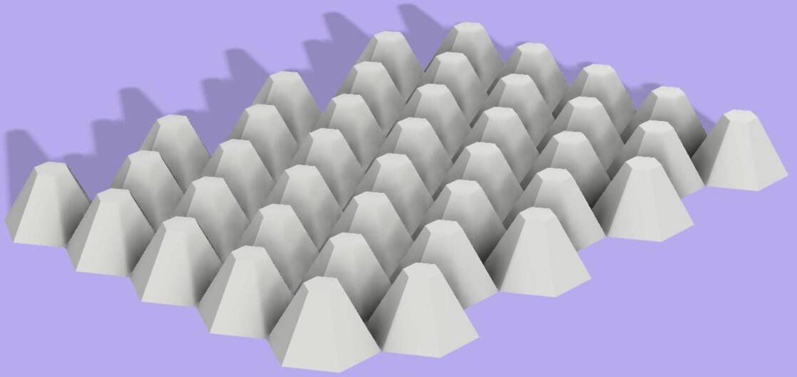
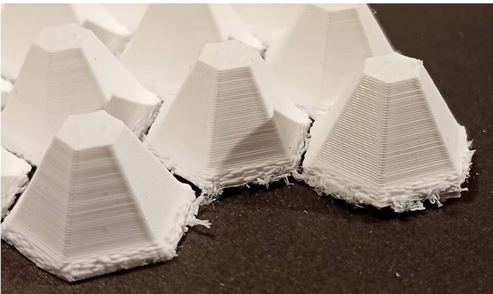
I always wanted to try to embed something inside a printed piece, like a textile. Therefore, I decided to try this. As a 3D design I created this pattern of cones, where a net-like textile can be embedded.
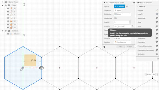
For starting the sketch, created one hexagon and cloned it in a rectangular pattern. I choose a distance between the hexxogons of 0.2 mm.
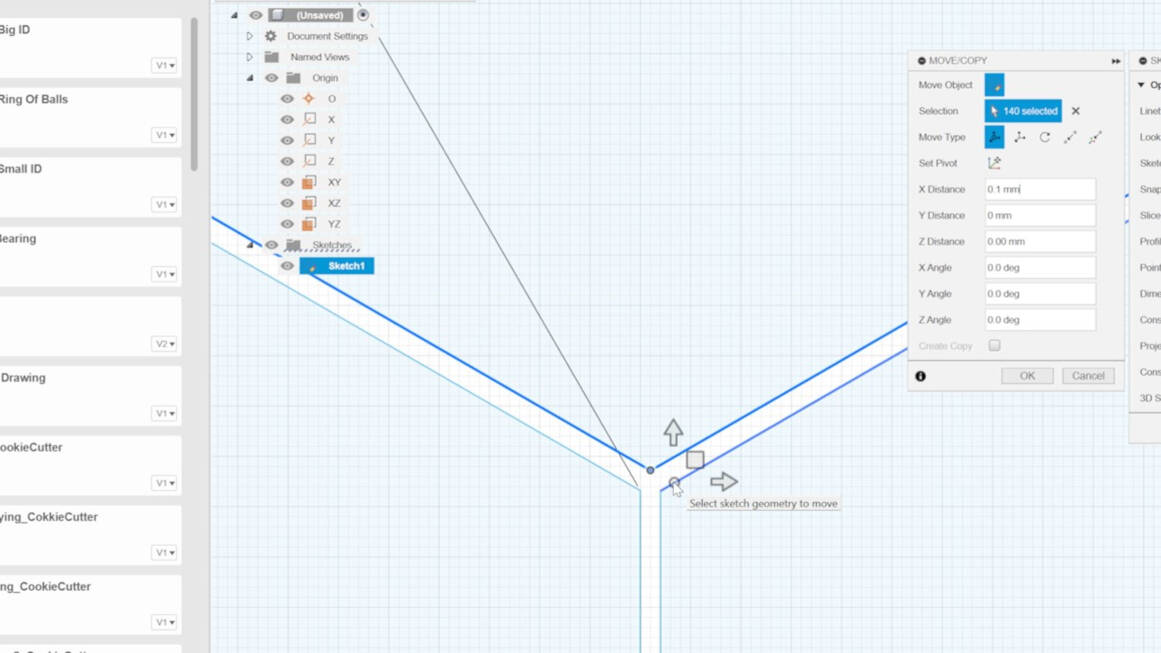
Unfortunately, the pattern production, is not really working side ways. To use the circular pattern would have been a better decision. In the end I used the Move/Copy function to create the right hexogonal pattern.
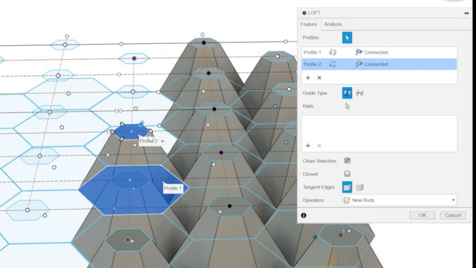
I wanted the cones of hexogons to loft to a smaller hexagonal surface. Therefore, I created a second plane with an offset of 3 cm from the original sketch plane and created the hexagons in a smaller size in the same pattern. To use the "Sloth" function, click on "Create" and select "Sloth". Choose the bottom face first and the the top face to create the sloth.
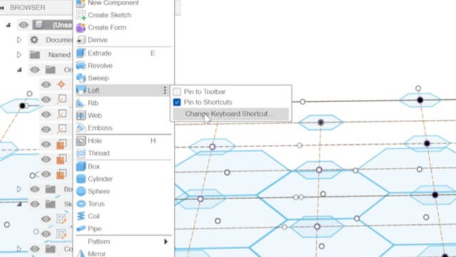
As I was using the sloth function several time I decided to set a shortcut for the function therefore click on the three dots next to "sloth" and select "Change Keyboard shortcut".
In the end I spend a lot of time using the same function again and again. For future design it is useful to know, that you also can start creating one body and using the array function to multiply it.
I rendered the cones in Fusion360 (matertrial: white ABS)
3D Printing the Design
Sheep
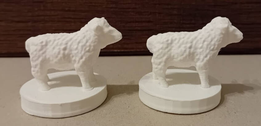
Cura served as the slicer for these prints, with customized parameters that have evolved over a year of using the printer. The settings included Dynamic Quality, a bed temperature of 70°C, a nozzle temperature of 230°C, and the use of a Brim for enhanced adhesion. Two sheep were printed—one with support structures and another without. Interestingly, the print with support structures took an additional 5 minutes. Following the completion of the print, the resulting sheep displayed the following characteristics:
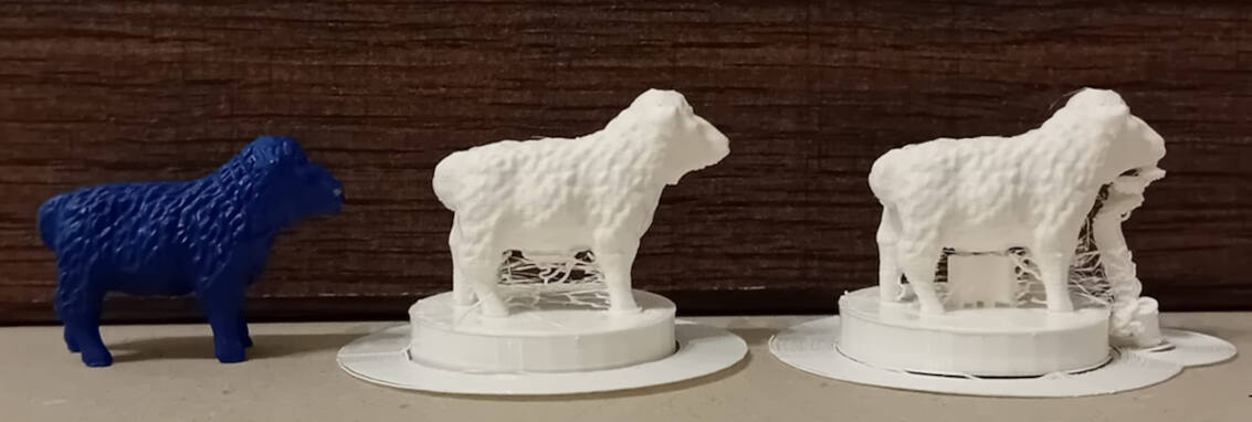
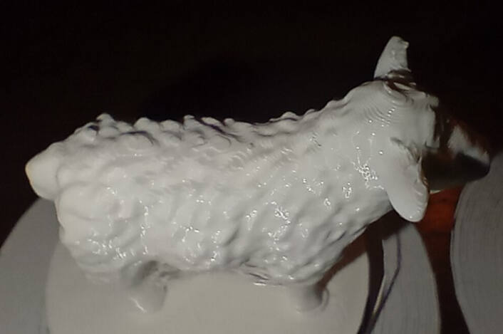
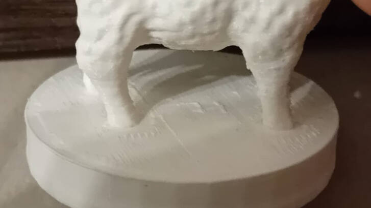
The resolution was surprisingly good for a piece of 4 x 3 x 3 cm. The layers were smooth and visible only in a close up.
To address the support structure remnants and stringing, I employed a combination of pliers and sandpaper. Removing the support structure was a relatively straightforward process, but reaching and cleaning up all the stringing, particularly on the small legs of the model, posed a bit of a challenge. After careful and meticulous effort, the final result achieved a cleaner and more refined appearance. Despite the intricacies of the small-scale model, the combination of pliers and sandpaper proved effective in enhancing the overall quality of the print.
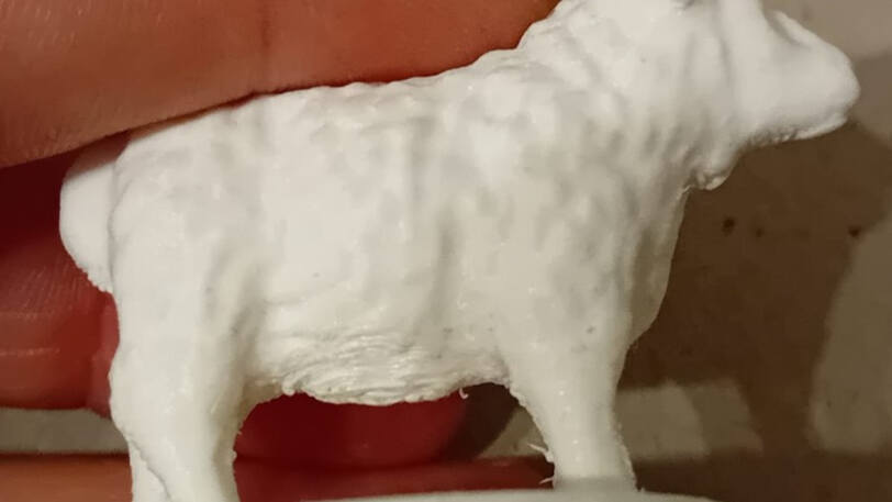
Sheep without support.
Sheep with support.
Bust
The print of the bust took 10 h as it was printed with dynamic quality and the size is 87 x 87 x 122 mm. The print worked out without any support.
Upon closer examination, certain aspects did not perform as expected. The pedestal test lacks sufficient size for legibility, and the measurements exhibit roughness in specific areas, which is evident in the print. Additionally, there is a minor deformation in the z-direction along the edges of the footprint.
Hexacones
To embed a textile into a print the print needs to stopped at one point during the processing. To include a stop Cura has the function to include G-code for it.
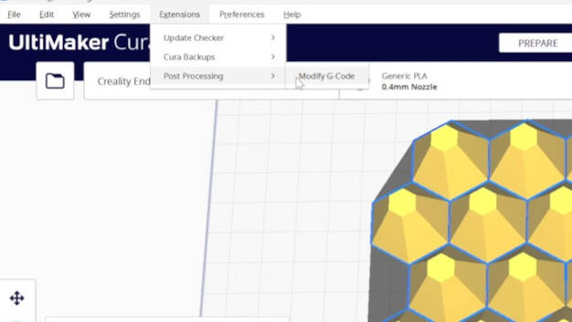
For going this go to "Extensions", "Post Processing", and click on "Modify G-Code".
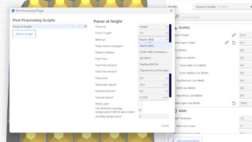
Select the "Pause at Height" code and change the height for the stop as you need it to be.
Otherwise, I used the same Cura settings as for the other prints.
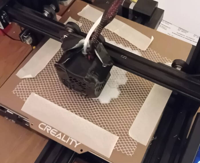
During the print, the printer paused after the first layer of material. Why not 1 mm? I have no idea, but that was no issue, I just started to embed the textile. I utilized crepe tape to secure the textile to the printing bed, aiming to maintain a flat surface.
Note: I tried electrical tape before, the heat from the bed and the surface structure disrupted its adhesion.
I manually clicked "pause" on the printer's interface to continue the print.
The print took 2:30 h, worked out well. Here is the print after taking it from the bed.
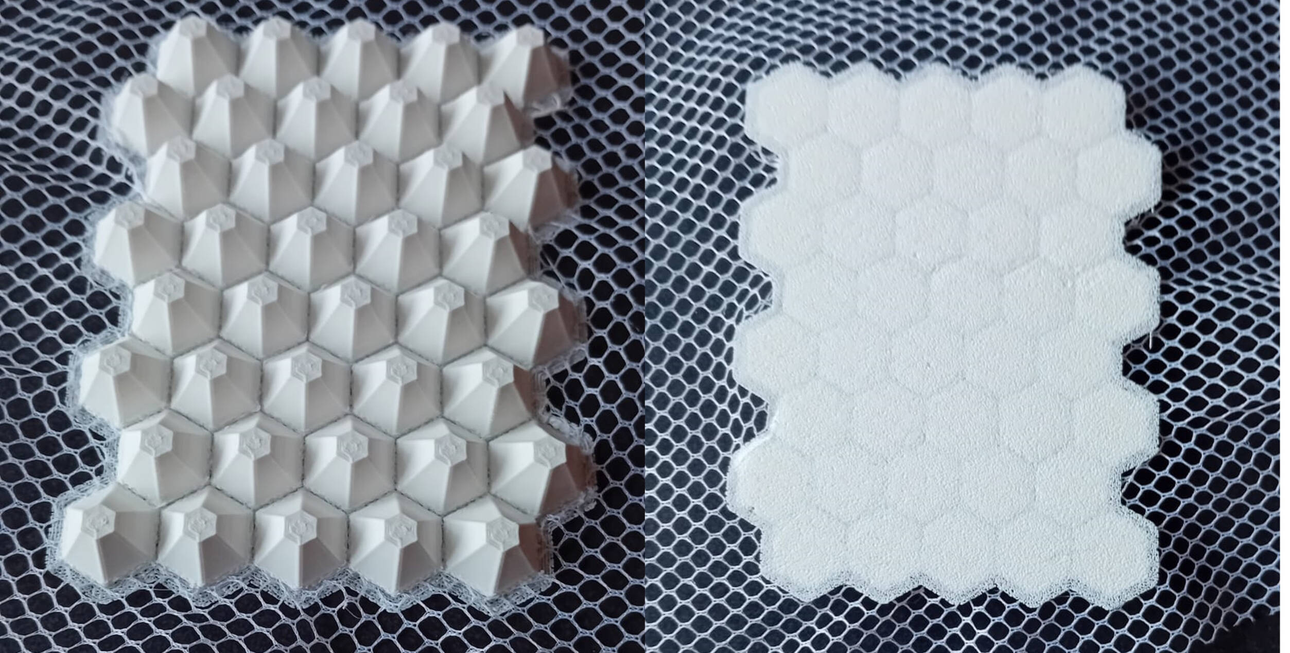
I carefully removed the print from the adhesion plate. Using scissors and the printer's pliers, I carefully trimmed away any loose textile sections. Attempting to refine the edges, I experimented with sanding, but unfortunately, the textile frayed, resulting in an untidy appearance.
Upon closer inspection of the initial layers, I noticed a deviation in the straightness of the layer lines, creating an intriguing pattern. While unintended, this distortion adds a unique quality to the print.
Reflection
3D Scanning vs Photogrammetry
To create a 3D model of a real life object. I tried to methods: 3D scanning anf Photogrammetry. In general there are some differences I noticed:
- 3D Scanning with the EinScan:
- + The scans produced by the professional 3D scanner yield highly detailed meshes, capturing intricate features of the scanned objects with precision
- + The scanner's output includes a variety of file types, providing flexibility and opening up numerous avenues for post-processing. This versatility enhances the creative possibilities and adaptability for different applications.
- + The scanner excels in providing accurate resolutions for the real size of objects. This ensures that the 3D models closely match the physical dimensions of the scanned items
- - Relatively high cost of the scanner
- - Scanning a person poses challenges with hair representation in the mesh
- - The scanner encounters difficulties with glass and reflective materials. I helped using a workaround, such as matte spray.
- Photogrammetry:
- + low-budget accessibility of the scanning process, as it only requires a camera, such as the one in a smartphone
- + There are several softwares available that can generate 3D meshes from photos, catering to both professionals and amateurs.
- + The method supports the creation of 3D models for a wide range of objects, including humans and other living subjects.
- - The precision of the resulting mesh depends on factors such as the software and camera used
- - Loss of object size information during the scanning process such as the accurate size
Meshroom and Polygon
Meshroom is an entirely open-source project and, in my opinion, relatively user-friendly. However, I encountered issues with the model outcome, as the mesh creation process did not yield satisfactory results. The software struggled to handle the pictures effectively, even when some were excluded from the mesh-building process.
Polygon offers the advantage of free access, allowing users to explore its capabilities without financial constraints. The software boasts a user-friendly interface, making it accessible to users of varying expertise levels. Additionally, Polygon excels in quickly generating meshes, contributing to an efficient workflow.
However, the free version of Polygon comes with limitations. These include constraints on the number of pictures for mesh creation, restrictions on the quality of output, and limitations on available file types. These restrictions can pose challenges during post-processing, impacting the versatility of the output files.
Additive vs. Subtractive
The assignment for the week challenged us to design and 3D print something achievable only through additive methods, unlike subtractive methods such as a CNC machine. Regrettably, I misconstrued the requirement initially. I believed it was sufficient to create designs that couldn't be executed using a 3-axis CNC machine, as none of my designs met this criterion.
Upon further consideration, I realized that a 4 or 5-axis CNC machine could potentially produce some of the components I designed. Notably, the pedestal of the sheep and the bust, when considered separately, could be manufactured subtractively.
To meet the true essence of the assignment, I had to create a third design that inherently couldn't be produced subtractively. This involved ensuring that no elements could be embedded in the material during the manufacturing process, a feature unique to additive methods.