WEEK 7
Computer-Controlled Machining
Group Assignment:
- Do your lab's safety training.
- test runout, alignment, fixturing, speeds, feeds, materials, and toolpaths for your machine.
Individual Assignment:
- Make (design+mill+assemble) something big (~meter-scale).
Downloadable Design Files Links
Sketching
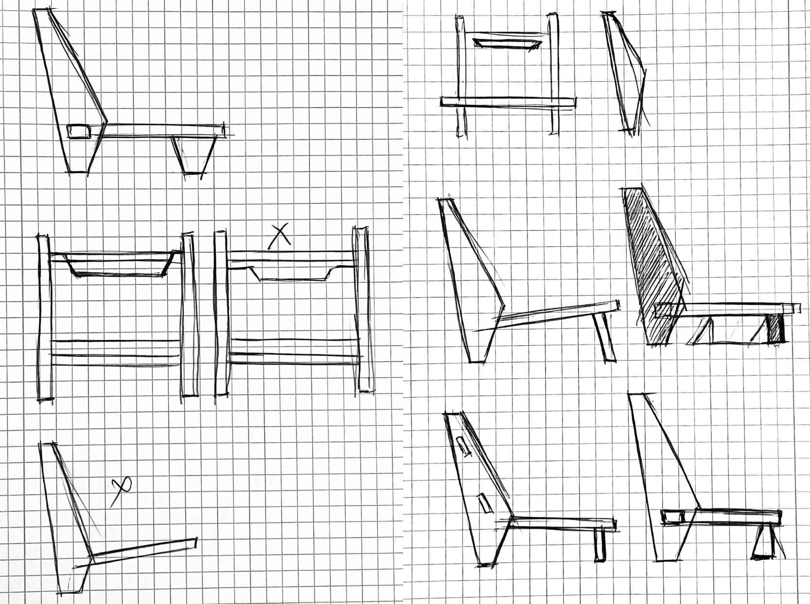
I decided to design a chair for this assignment. Before drawing in Fusion 360 as 3D, I sketched some designs to find a final version.
3D Drawing on Fusion
I aimed to design a low chair, that I can use in my room while reading a book :) So, I started to draw a 3d model on Fusion according to my sketches. I was almost finishing the 3d model however, I realized that there were some problems with my design.
When I explained the problem I faced with my model, my instructor offered to use the dog bones technique and wooden duvels to stabilize the legs of the chair. Then we draw the chair according to these principles. Since it is very important to be able to design for CNC, I would like to give more information about this step.
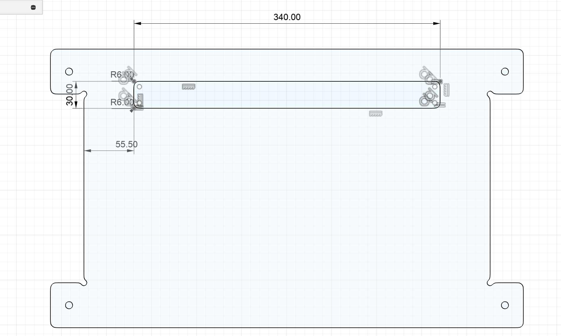
I started the design by drawing the big legs. I used the "Line" tool for this drawing. In the drawing, it was important to determine the area where the back of the chair would connect to the leg. Using the "Measure" tool, I calculated where the back area should be located. My goal here was to design the back area in harmony with the leg, avoiding it being close to the ground.
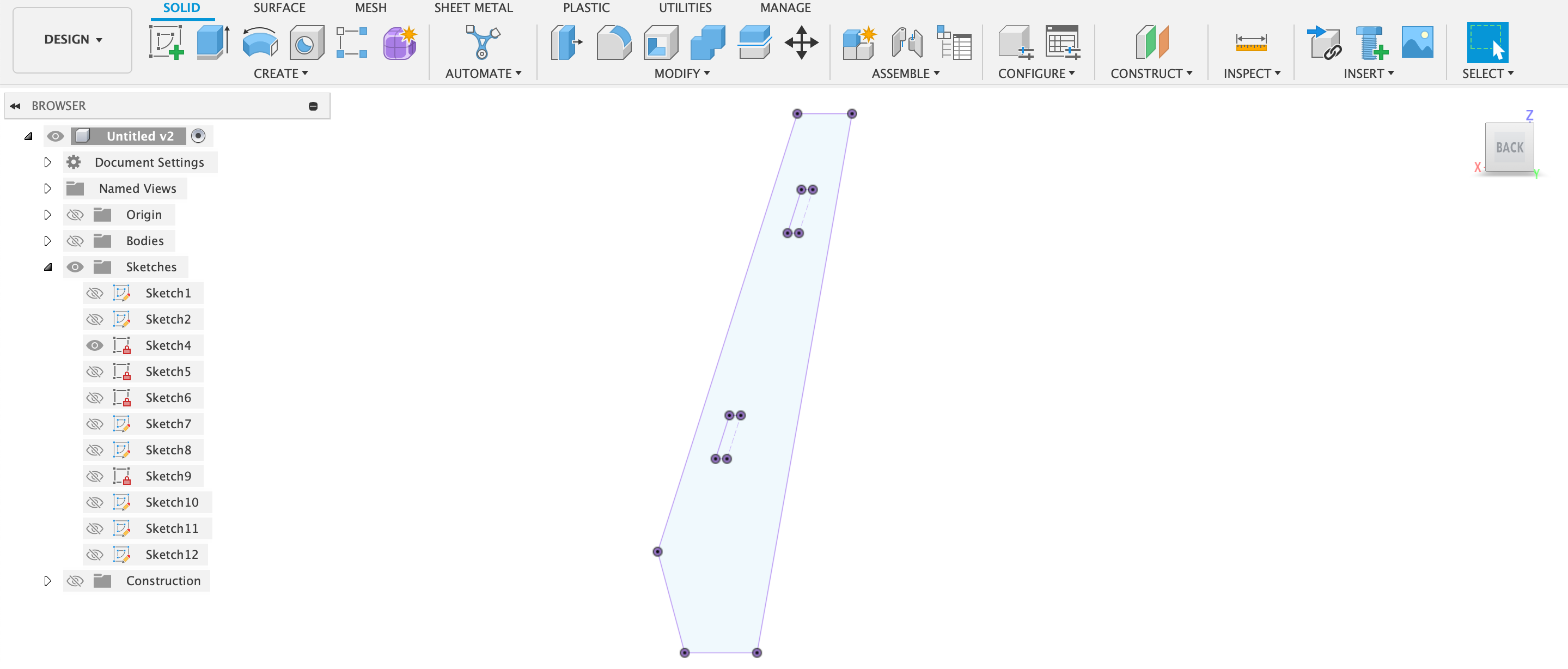
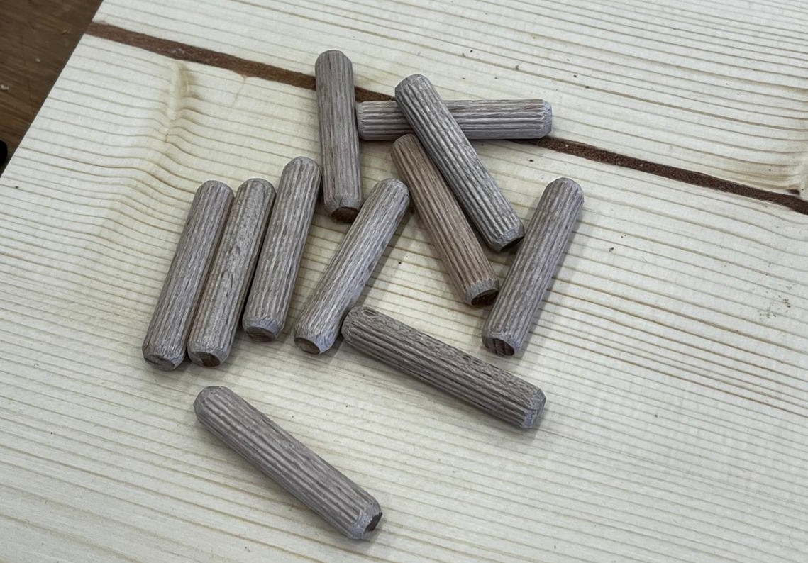
In the second stage, I created a sketch for the seating area, where I first drew a rectangle to define the boundaries of the seating area, and then I drew the protrusions to which the small legs would be attached. At the suggestion of my supervisor, we decided to use the dog bone method in my design. This method allows the parts to be joined together more easily. In addition to this method, I also added holes for the feet to be fixed without moving and for the attachment areas. These holes are designed for the use of dowels. With this method, we aimed to keep the feet stable.
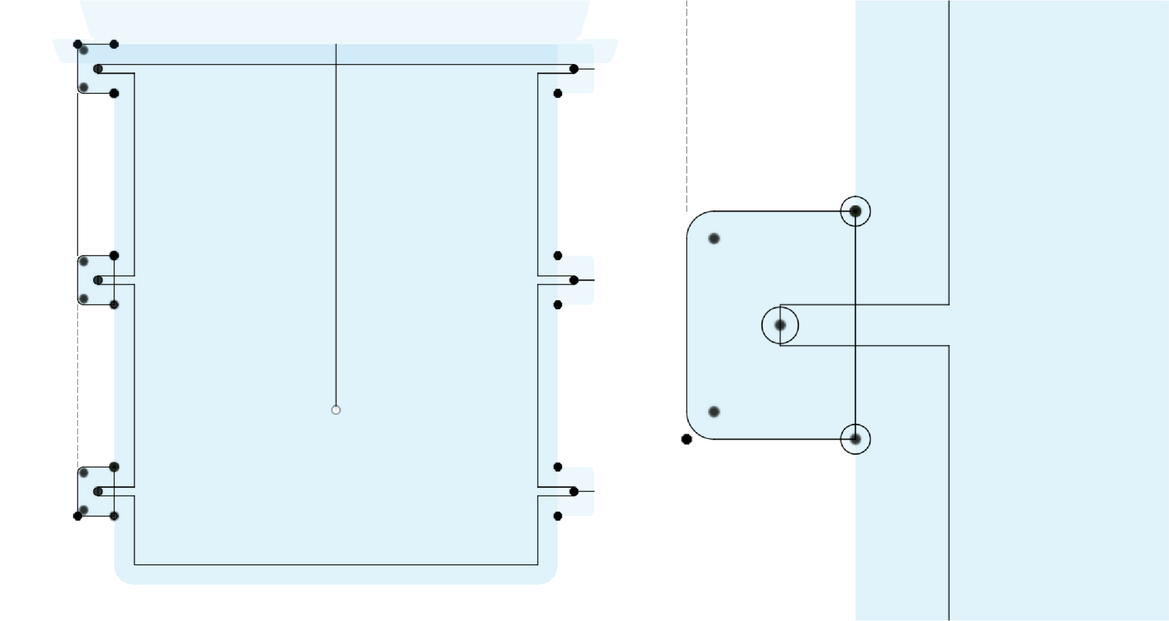
In the third step, I drew the back of the chair and determined the width of the back area according to the width of the seating area. I applied the "dog bone" technique and added my holes, as I did in the big foot and seating area.
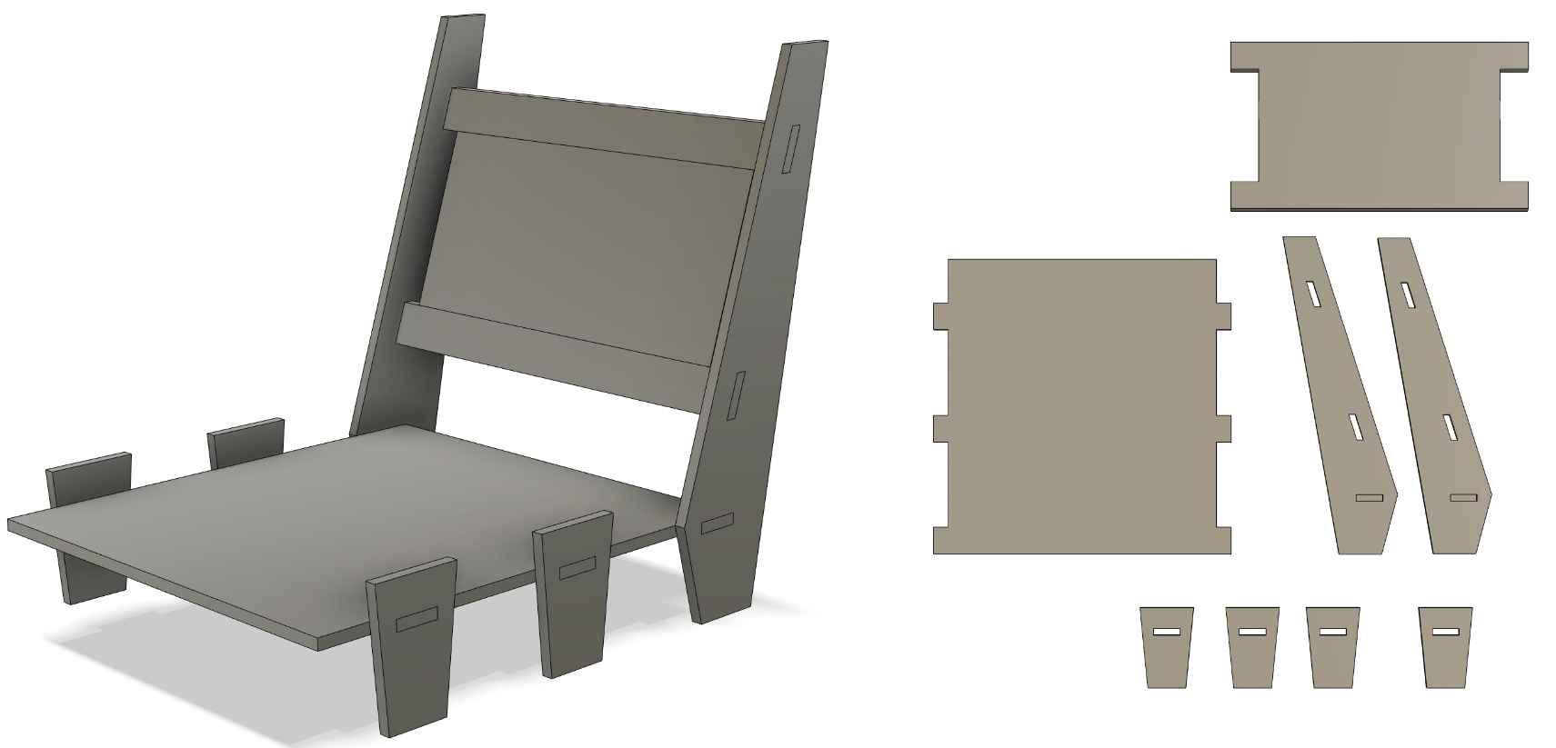
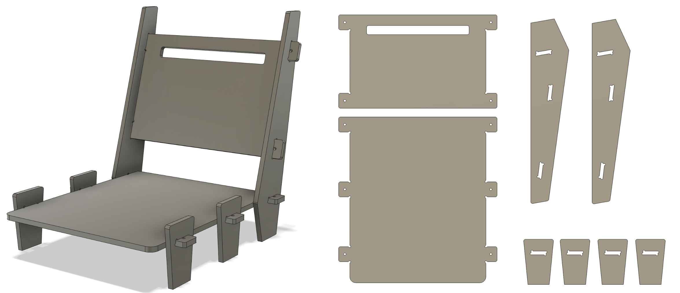
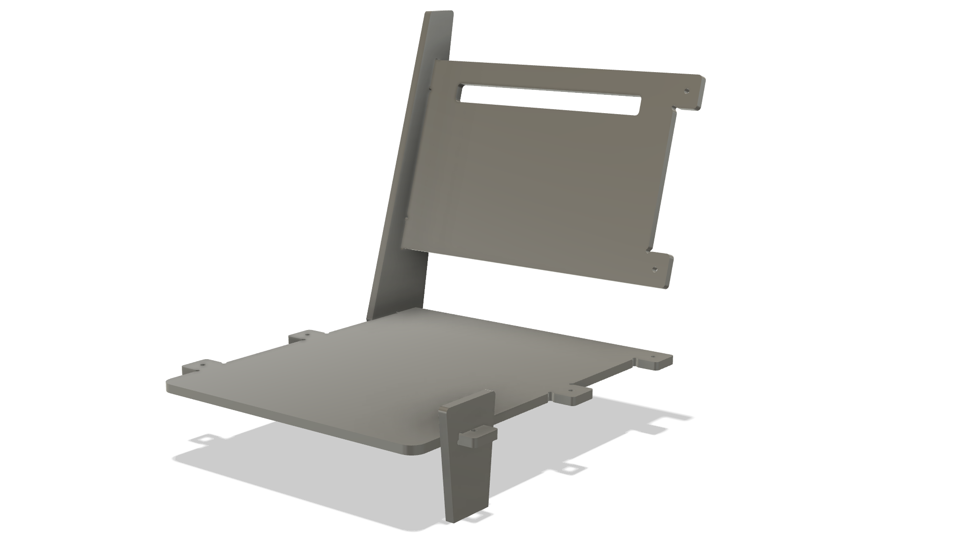
And finally, after drawing my little feet, I created bodies using the "exturede" tool on my sketches. My back, seating area and big foot bodies were ready. I only created one sketch each for the big and small feet. After creating the bodies, I copied them and moved them to where they needed to be.
CAM
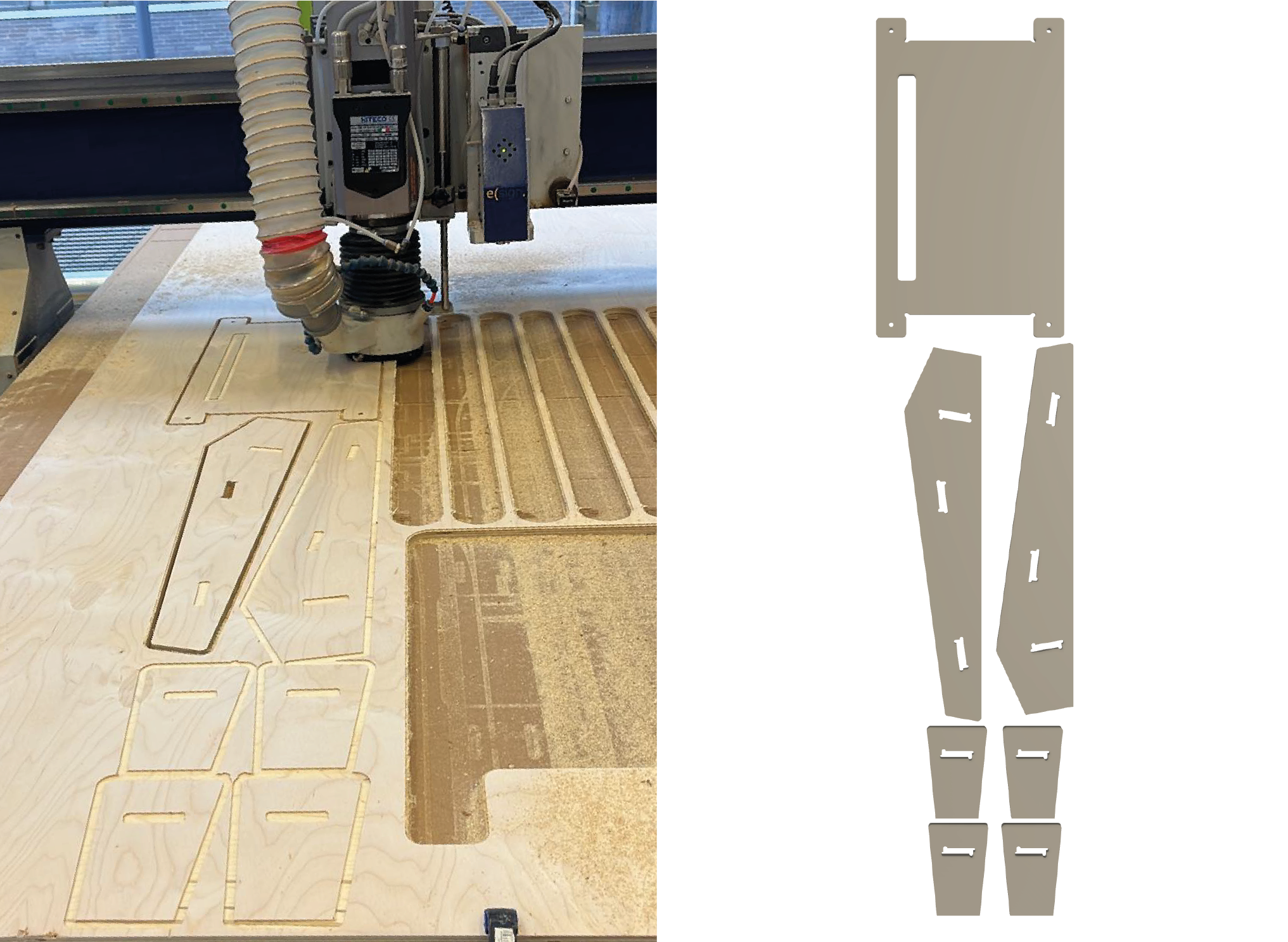
First, I needed to prepare my drawing for cutting. We are 4 students at Fablab Kamplintfort and I was the last student to make the cut. For this reason, I prepared my pieces for cutting according to the remaining material. I checked the amount of remaining ingredients and did the "Nesting" process accordingly. This means using the available space in the most effective way and arranging the pieces. Additionally, I decided to cut the chair pieces in two stages.
I followed the steps we completed for the sample task described in the group assignment for the CAM process and I can summarize it as follows;
- After completing the nesting process, I moved from the "Design" tab to the "Manufacturing" tab in Fusion 360. You can do this by pressing the large button in the upper left corner of the screen.
- I created a new setup by following this path. Go to the "Set up" tab in the Main bar at the top - select "New set up"
- In the window that opens, select which machine you are designing for. Then proceed to the "Stock point-Box point" stage. In this section, you choose the starting point of the design. I defined the origin point by placing the x axis on the right side of the design.
- Go to the "Stock" tab and select "absolute size box". And click the "ok" button at the bottom of the window.
- Again, find the "2D" tab in the main menu above and click on "2D pocket".
- Click the "Library" option in the window that opens, then click the plus sign in the upper left corner.
- After doing this step, a library of tools will open. Here you need to choose a vehicle according to the machinery and tools you have. We chose "Flat and mile".
- After selecting the vehicle, it is necessary to enter data to identify the vehicle in the window that opens. Therefore, set the parameters for "milling tool" and "tool holder" in the "cutter" panel. The parameters we use are Diameter:6mm, Schaft Diameter:6mm, Overall Length:36mm, Lenght Below Holder: 24mm, Shoulder Lenght: 21mm, Flute Lenght:18mm.
- Go to the "Cutting Data" panel. Here we created data such as "feeding rate". Detailed information at this stage can be found in the group assignment. After all the settings are made, press "Accept" and close the window.
- Click on the "2d" tab in the top main panel and follow this path. 2D--- 2D Pocket--- Geometry. Then select the face you want to create a pocket on.
- Switch to the "Passes" tab and enable the "Multiple Depths" option. I chose the parameters according to my design. And tehn chose okey.
- The next step is to create cutouts of an entire object. Go to "2D" again and select "2D contour". Select the faces you want to contour.
- Go to the "Heights" tab and check the "Bottom Height" option. Set relative contour to 0.1. Activate "Multiple Depths" and click Okey.
- After completing these steps, you will see the adjustment you created as a tab on the left of the screen. Right click on this tab and dublicate.
- Select the copied setting and open the final cut, create another contour.
- It is necessary to create a nest for cutting. Click “2D” again and select “Slot.” Then select the contour of the slot and click "OK" to continue.
- Right-click “Setup” and select “Post Processing” to create the cut file.
- Click on the "folder" icon and select "Local" in the new window that opens. Finally, click "import". Meanwhile, determine which file you want to export and to which location on your computer you want to transfer it and finish the process.
I did my cutting in two stages. The first is the back area and feet, which I showed above, and the second is the sitting area.
Safety
The CNC machine is a powerful tool that can be dangerous if not used properly. It is important to follow the safety guidelines to ensure that you and others are safe while using the machine. Before the machine starts;
- To protect our ears from the loud sound of the machine, we should wear either headphones or earplugs.
- Glasses must be worn against any harm from the machine.
- Keep the machines and surrounding clear. You can use vacum cleaner for collecting the dust and rest of the wood.
- Be aware place of the fire extinguisher.
- Be aware where are the safety buttons! There are buttons on the bottom part, on the left side, and the right side of the machine.
While the machine working;
- If you hear any strange voice or see an unexpected situation on the machine, use the safety button to turn off the machine.
- Do not cross the safety band. Set a distance between the machine and you.
Operating CNC
We turned on the computer connected to the CNC to start cutting. In order for the cutting to be done, the machine must have the cutting tool. To do this, follow the following steps in the computer interface. Go to user menu --- Click the "Get Tool" button on the bottom right ---- Enter the tool number.
For the next stage, the zero point where the machine will start cutting must be determined. That's why we determined the x and y values of the coordinates where the cutting head will be positioned in the interface. We then carefully moved the cutting head towards the cutting table to set the z coordinate. The moment we noticed the sound change here was our maximum limit.
It is necessary to adjust the extraction system before starting the cutting. This is why we followed the following steps;
- Activate dust collection system
- Make sure that the path to and from the CNC is clear at the control station of the extraction system.
Cutting
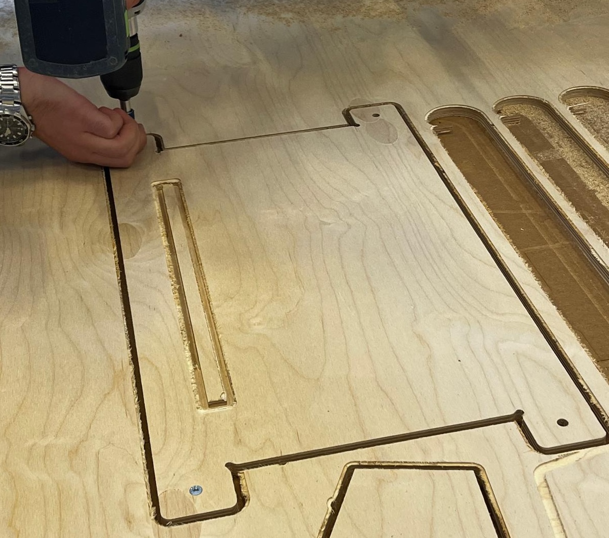
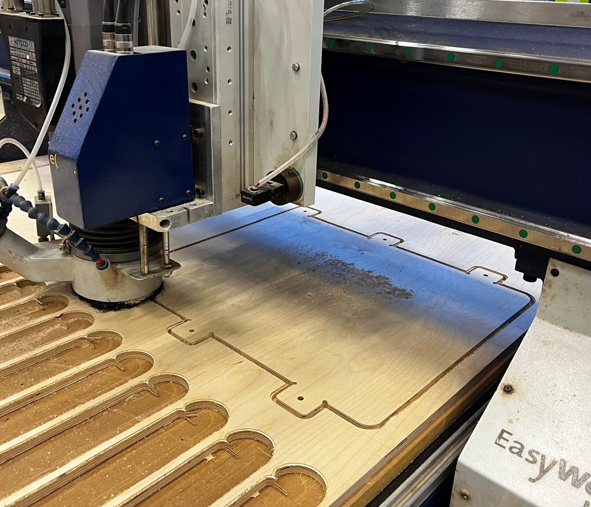
We used 12.55mm multiplex plates in cutting. Since I used the remaining material from the previous job, we operated the CNC to make the cut to the left of the material. After operating the CNC, we started cutting. We had secured the material to the cutting bed with large clips and assumed that the vacuum created by the CNC would be sufficient to keep the wood stable.
However, things did not go as we expected. A few minutes after the cutting started and as the pieces began to be cut, the wood began to move as there were fewer surfaces to fix the material. For this reason, we immediately stopped the CNC operation. My supervisor didn't want to screw the wood onto the cutting bed. Because this cuts damages the bed and leaves a mark. But when we encountered such a problem, we had to do it. After securing the material and returning the moving parts to their original position, we continued operating the CNC.
After the first cut was completed, we completed the cutting of the seat piece using the rest of the material. We applied the same process to cut this piece.
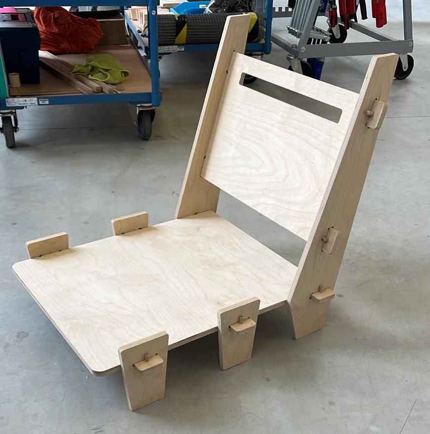
Result
After all the pieces were cut, I took them all off the cutting bed. I started assembling the pieces with excitement, but the pieces were too tight to fit into each other. For this reason, I started another step.
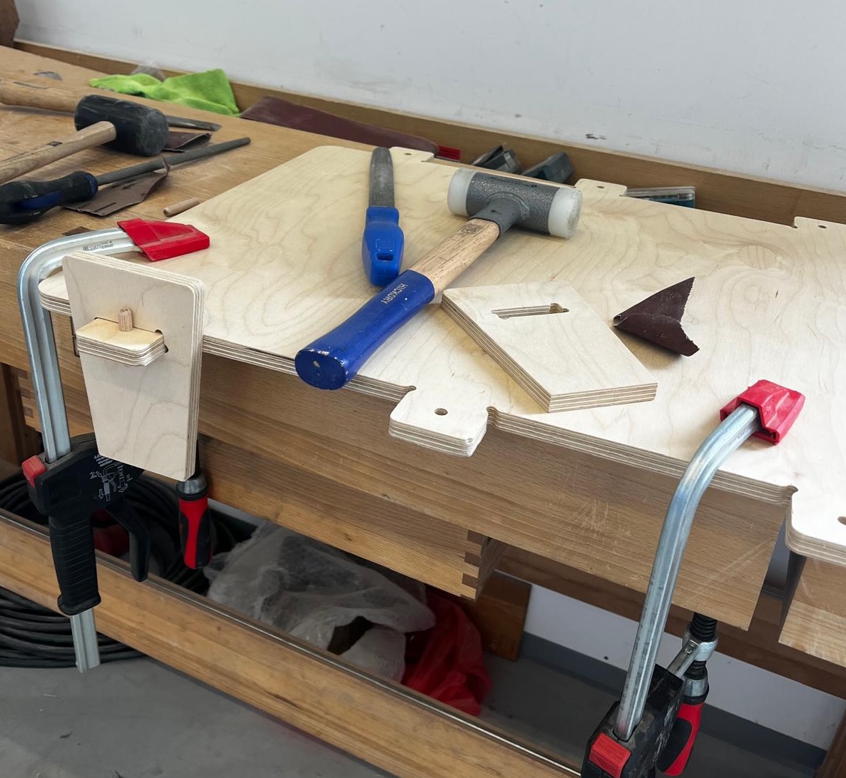
First, I started sanding the holes where the feet would go, using a large-tooth sander. After sanding enough I placed the legs on the ledges and used the wood hammer to set them into place. To make this process more comfortable, I fixed the chair from the seat to the work table with clamps. After moving the legs to the position I wanted, I fixed the feet by placing the dowels in the holes.
First, I finished placing the legs of the left side. Then I attached the back piece and finally placed the feet on the right side. And finally my chair is ready.