WEEK 3
Computer-controlled cutting
Group Assignment:
- Characterize your lasercutter's focus, power, speed, rate, kerf, joint clearance and types.
Individual Assignment:
- Cut something on the vinylcutter.
- Design, lasercut, and document a parametric construction kit, accounting for the lasercutter kerf, which can be assembled in multiple ways, and for extra credit include elements that aren't flat.
Downloadable Design Files Links
- You can download my original 2D design file for vinyl cutting.
- You can download my original 2D SVG design file for laser cutting.
- Here you can find Fusion360 3D design file.
Vinyl Cutting
For this assignment, I wanted to create a computer sticker using the drawing I created last week to experiment vinyl cutting.
- First I installed Silhouette Studio 2 on my computer.
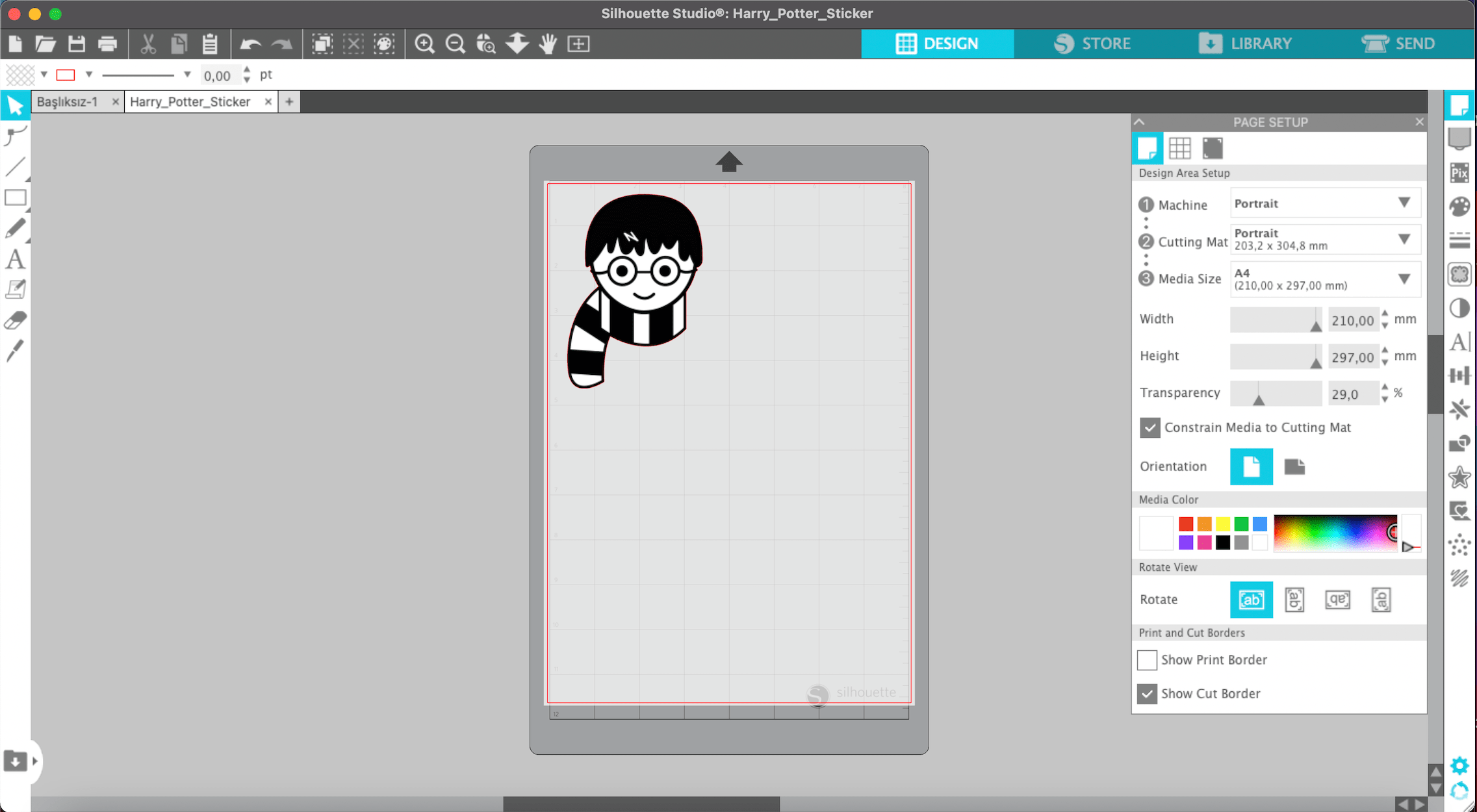
- I imported my drawing to Silhouette Studio 2. On the left-side corner, you can check which folder you are in.
- As a next step, I arranged the settings for the design area which I will be placed on the machine. Machine---Portrait, Cutting Mat---Portrait, Media Size---A4.
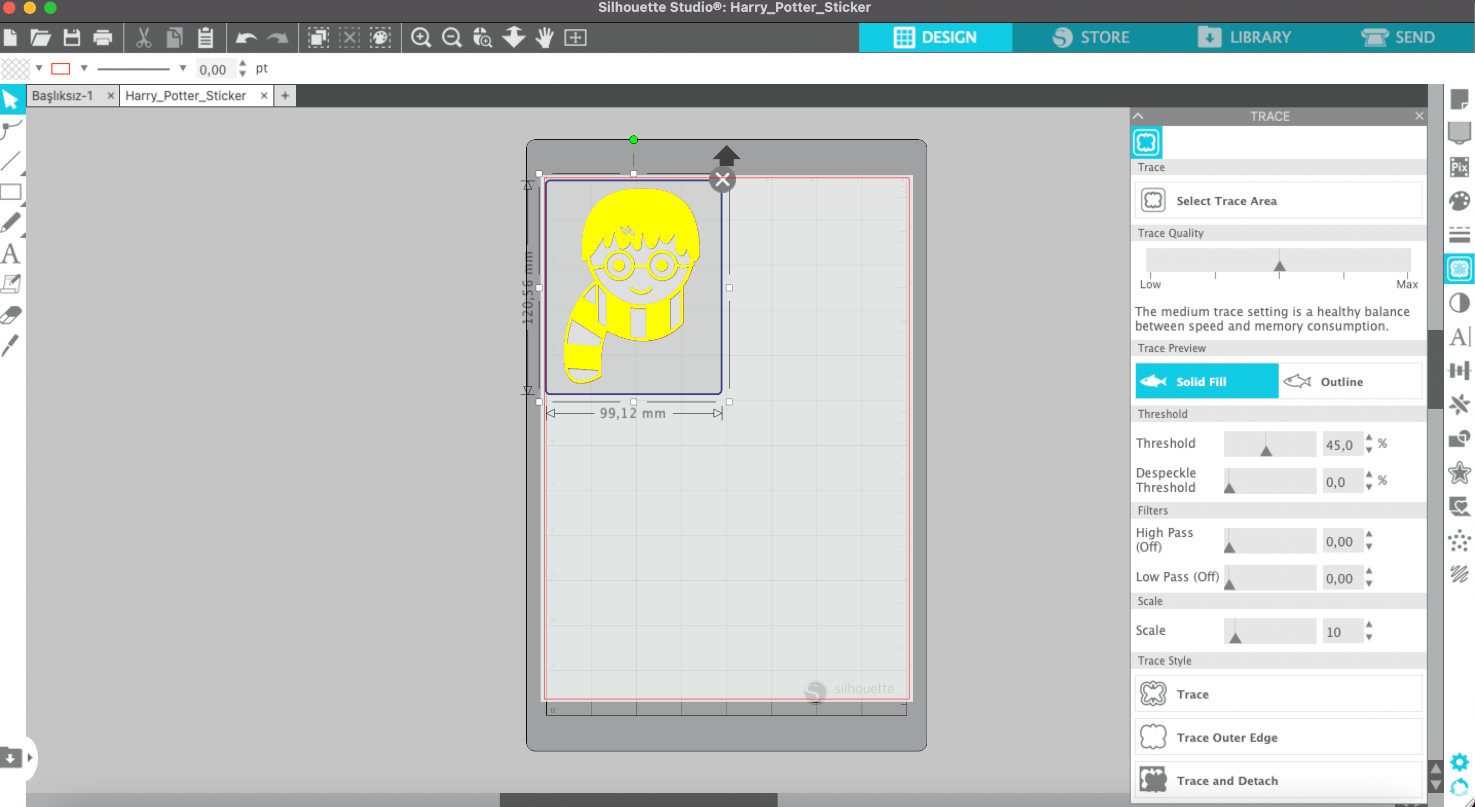
- I chose the butterfly icon on the right sidebar to trace the image. Under "Select trace area" you can determine the place where want to trace. And I selected the solid trace preference.
- When I looked at the dimensions of the image I realized that It was quite big which is why I resized it as smaller by using a scaling slider.
- After my design was ready to be sent to the machine to cut, I clicked the send button which is placed in the right top corner.
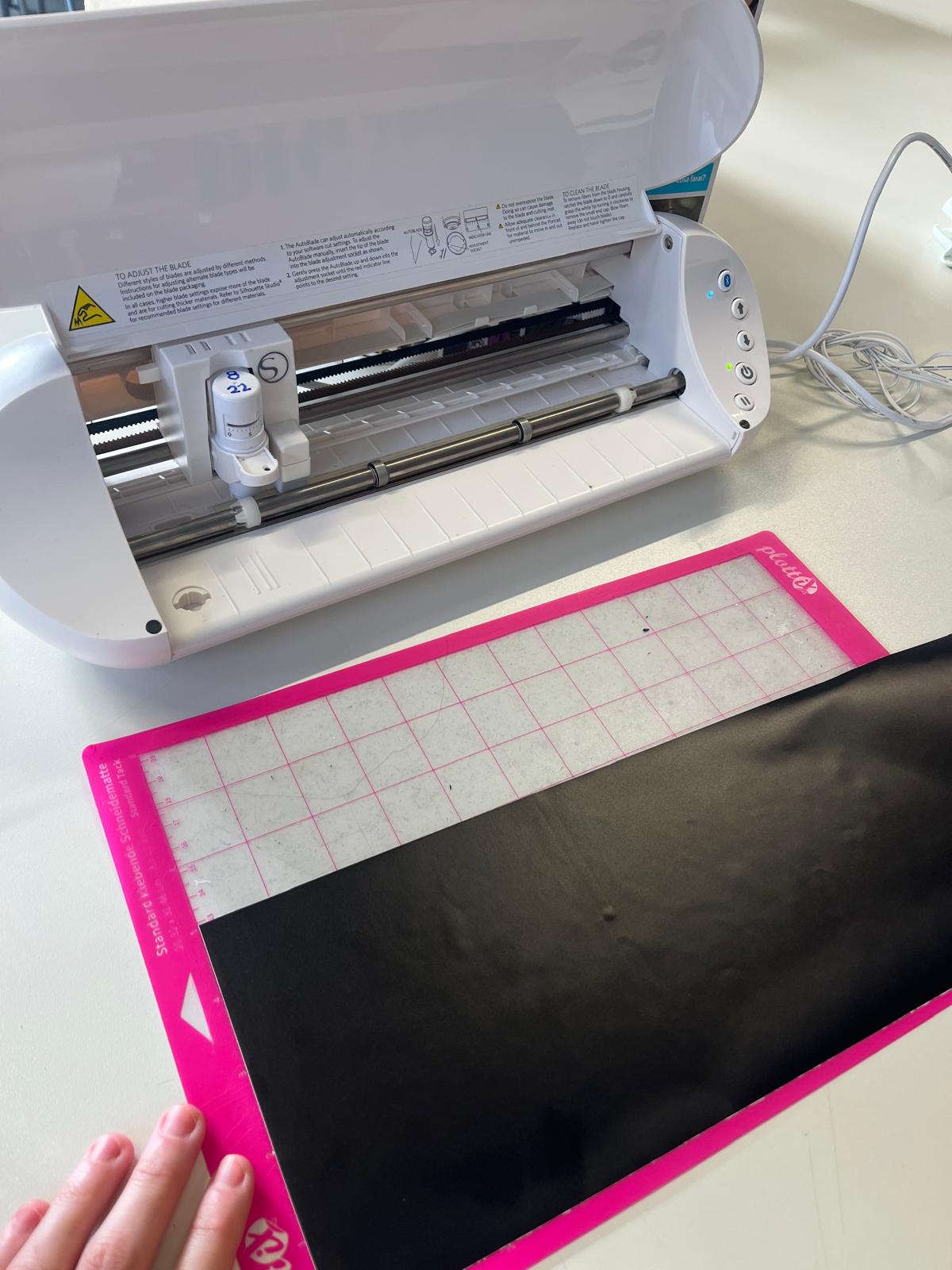
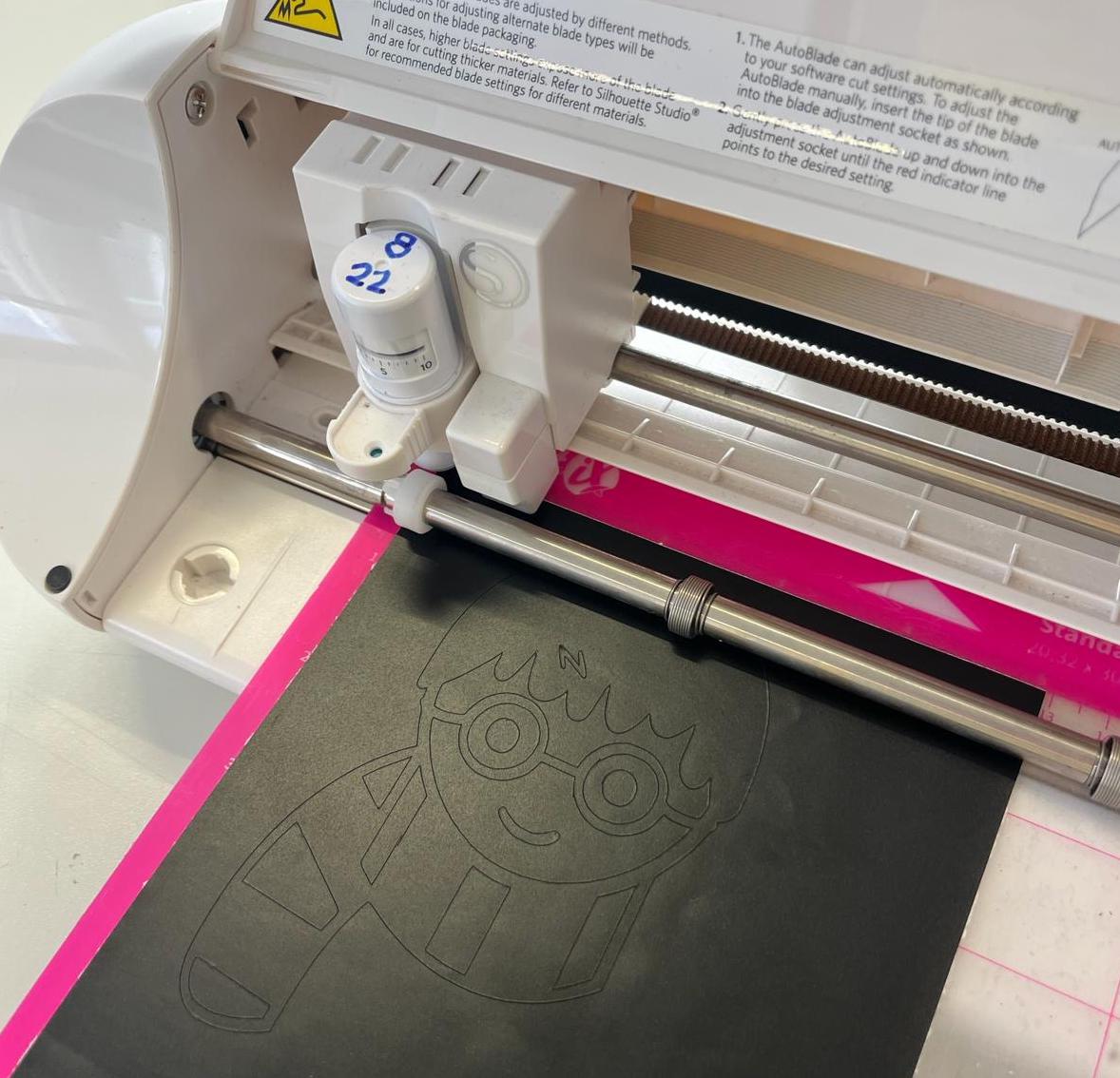
- Then I placed the vinyl into the machine with the cutting pad. I let the machine to cut the material. In this image you can see how I placed the vinyl on the cutting board. It is important to align the material on the cutting board to get a good cut. After placing the cutting board by aligning the cutting tool on the left side of the machine, I pressed the up arrow on the right side of the machine and loaded the cutting board and material into the machine. This way my material was ready for cutting.
- Shortly after placing the material, the cutting began. In the video below I took only a short video about the assignment. For this reason, I am adding the cutting video of my final project to show how the vinyl cutting machine cuts.
- Unlike a laser cutting machine, the cutting head of a vinyl cutting machine moves only in the x-axis. The loaded material is moved forward and backward in the y-axis thanks to the cylinder positioned horizontally in the machine. In this way, the cut is completed. The image with the red vinyl belongs to my final project. With this video I wanted to show how the vinyl cutter works.
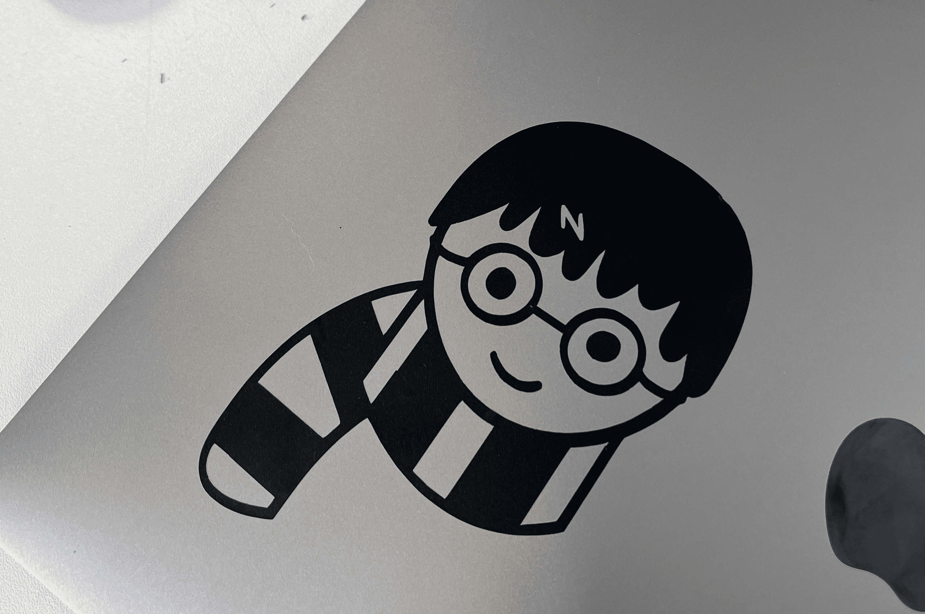
- After a short time, my result was there.
- After the cutting was completed, I used a transfer tool to lift the cut surface out of the adhesive area. This tool has a severed tip, which allows it to get under the thin surface of the vinyl and lift it easily. First I lifted the body of the character and pasted it on my computer, then I removed the character's eyes.
I am quite happy about my result!
Parametric construction kit - Design
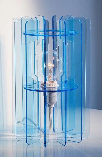
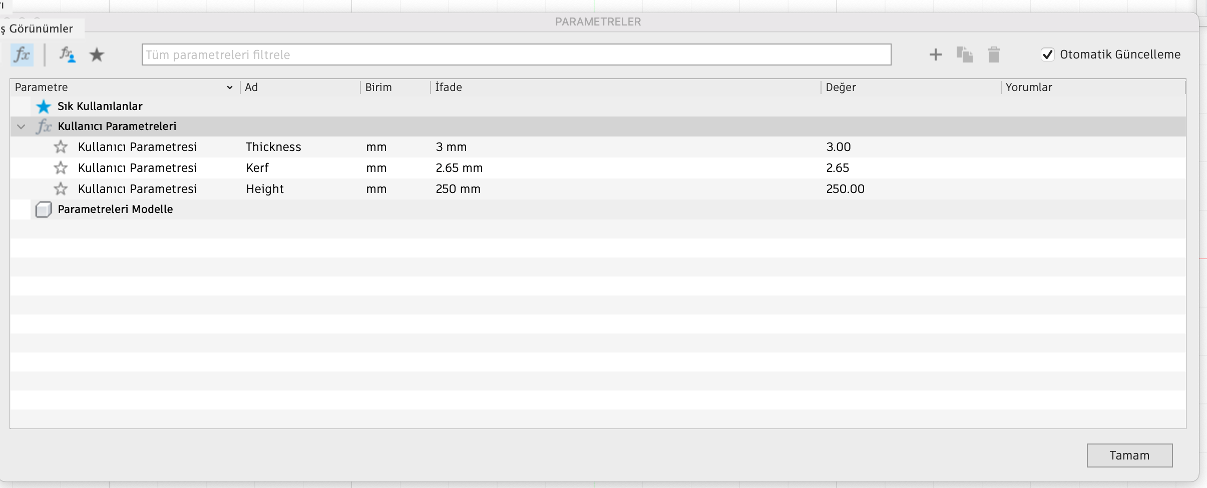
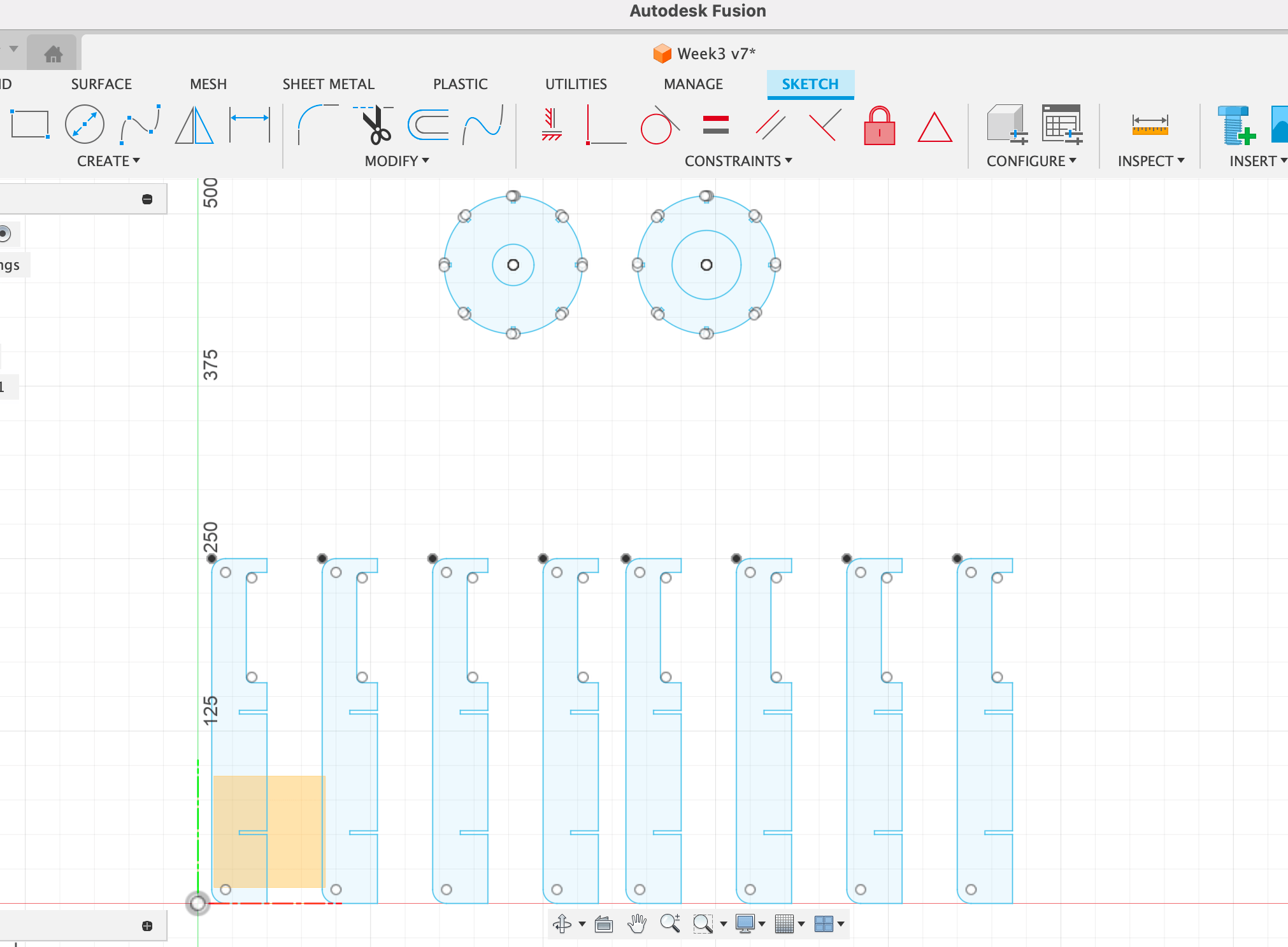
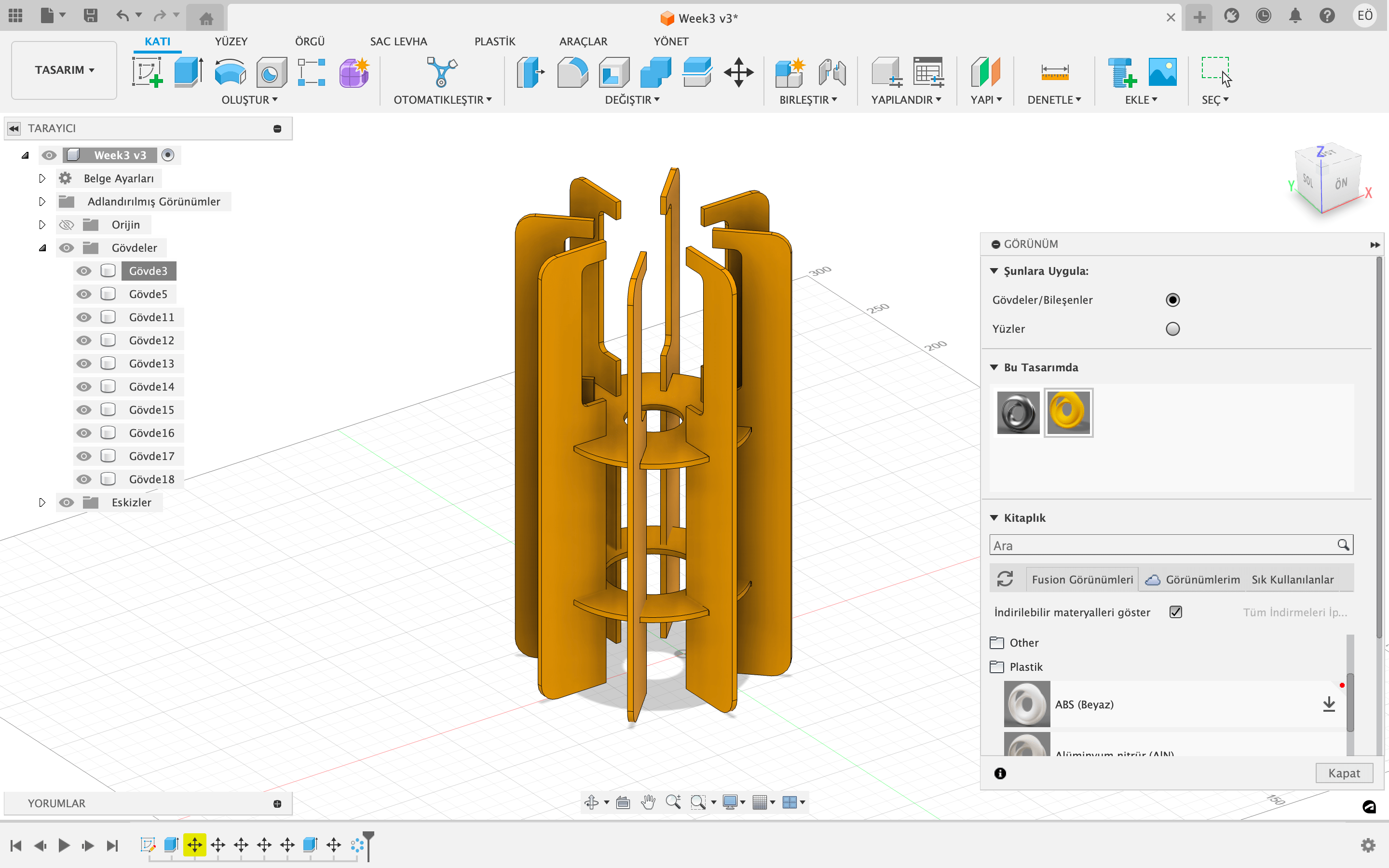
For the individual laser cutting assignment I wanted to create a lampshade. I research on Pinterest to find a nice inspiration. As a result of my research, I came up with a cool design that I can work on it. I did not want to replicate the design so, I made some changes to the form. You can see the original image here . I am familiar with Fusion 360. The drawing part was not challenging for me. However, while I was deciding on the measurement of the lampshade I couldn't be sure which one was the suitable. So, I checked the lamp bubble size then I set the measurement according to that.
Parametric construction kit - Laser Cutting
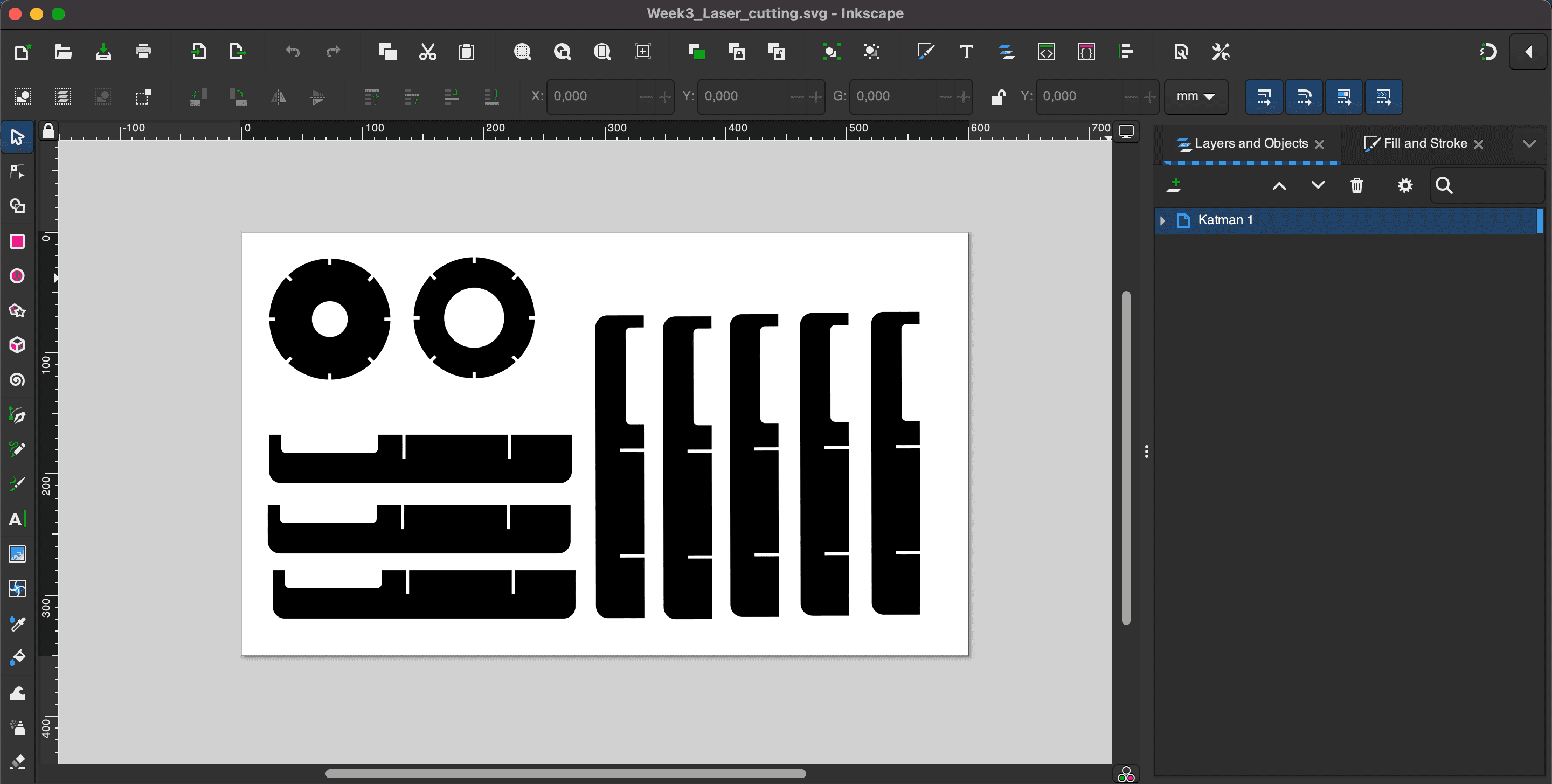
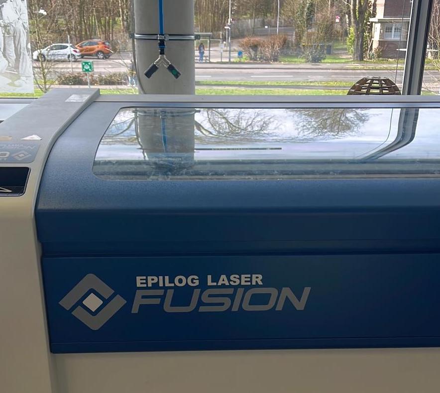
After creating an SVG file, I uploaded it another PC which was connected to the laser cutter. I opened my drawing in the Inkscape program on the computer connected to the machine. Then, I followed the File--print path and transferred my drawing to the epilog laser's own program. In our Kamp Lintfort Fablab, we use Epilog Laser Fusion. During the group assignment, we determined the settings for MDF as follows; cutting speed of 5%, power of 70% and frequency 30%. After all the adjustments are completed, it is necessary to make some adjustments on the machine before clicking the print button at the bottom right of the interface.
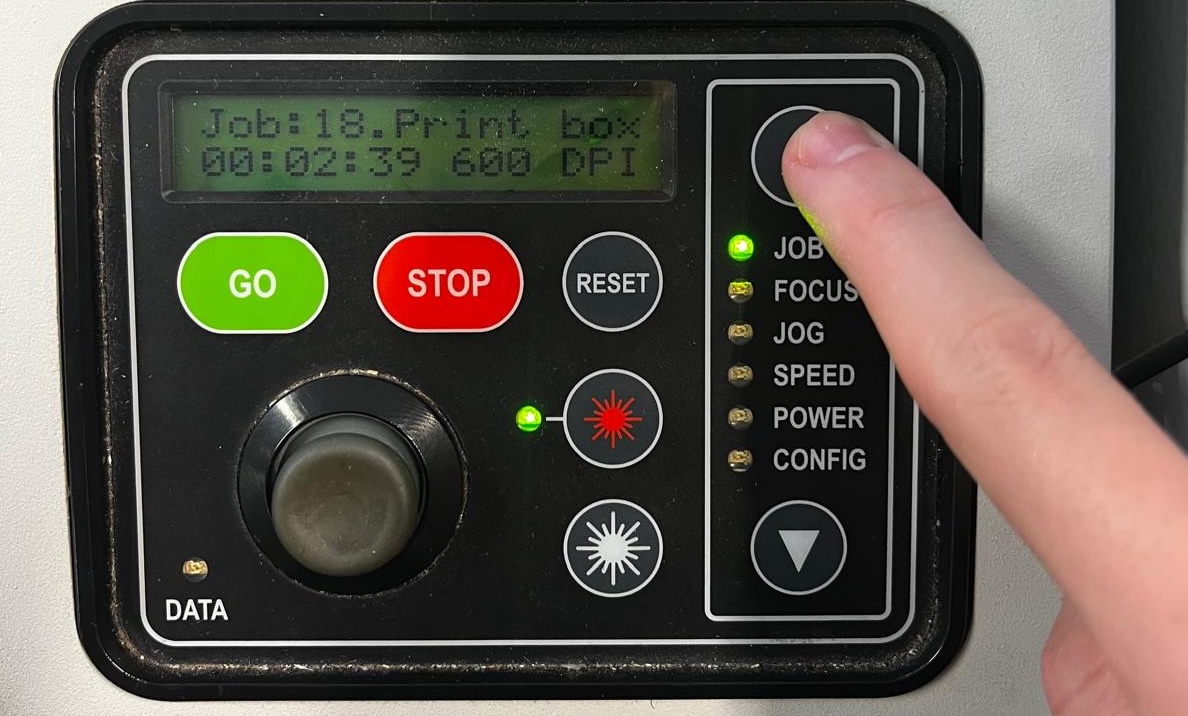
It is important to adjust the bed height of the laser machine and the position of the cutter. For this reason, the bed height can be changed by selecting "focus" on the panel on the right of the machine. After selecting focus, the bed is moved via the joy stick. To determine the position of the cutter, "Jog" is selected and moved again with the joystick. After deciding on the new location, press the joy stick to confirm.
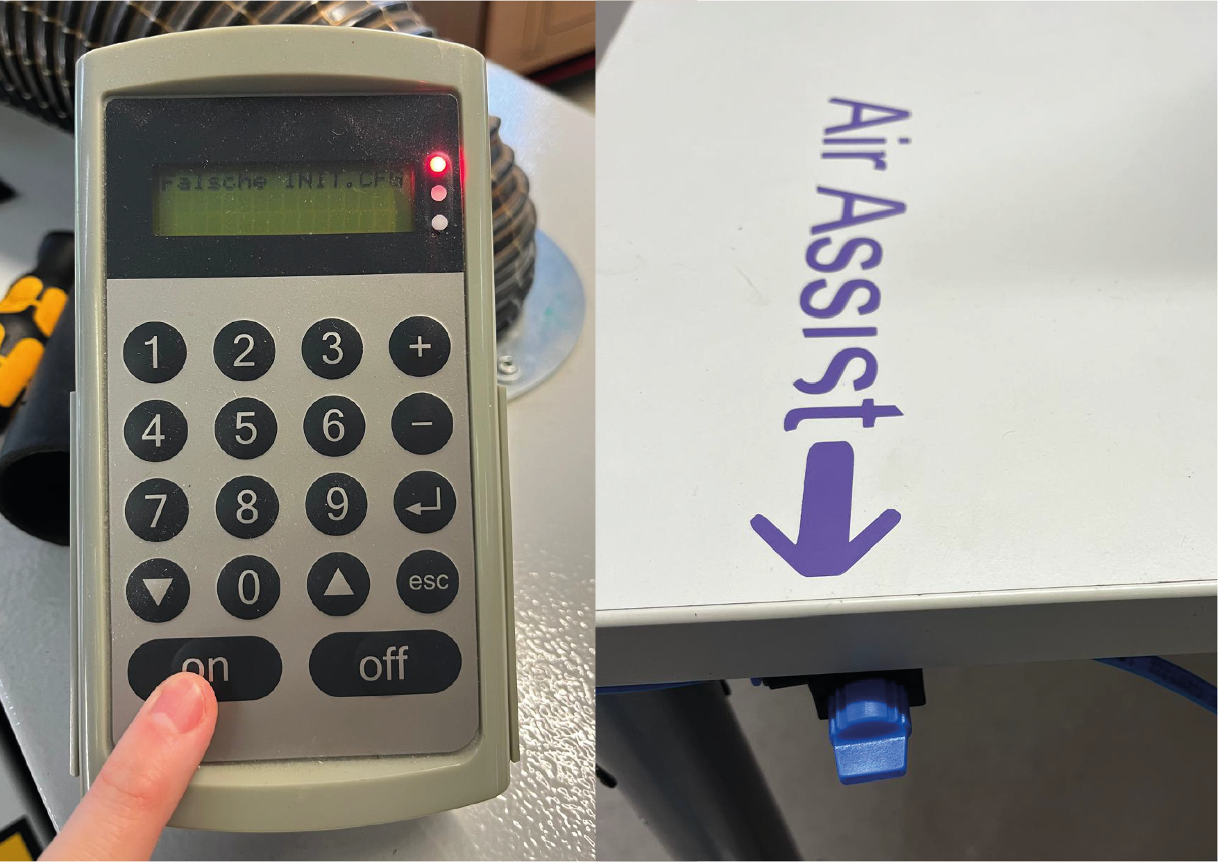
It is also very important to turn on the air pressure before transferring the task to the machine. Otherwise, flames may break out while the material is being cut.
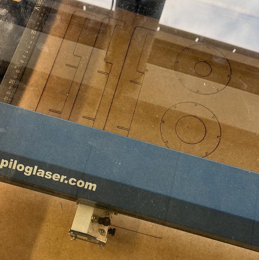
After making all the adjustments on the machine, I pressed the "print" button on the computer interface and after pressing the "go" button on the laser machine, the cutting started.
You can find more information, about how we operate the laser cutting machine in our group assignment.Here you can find our group work.
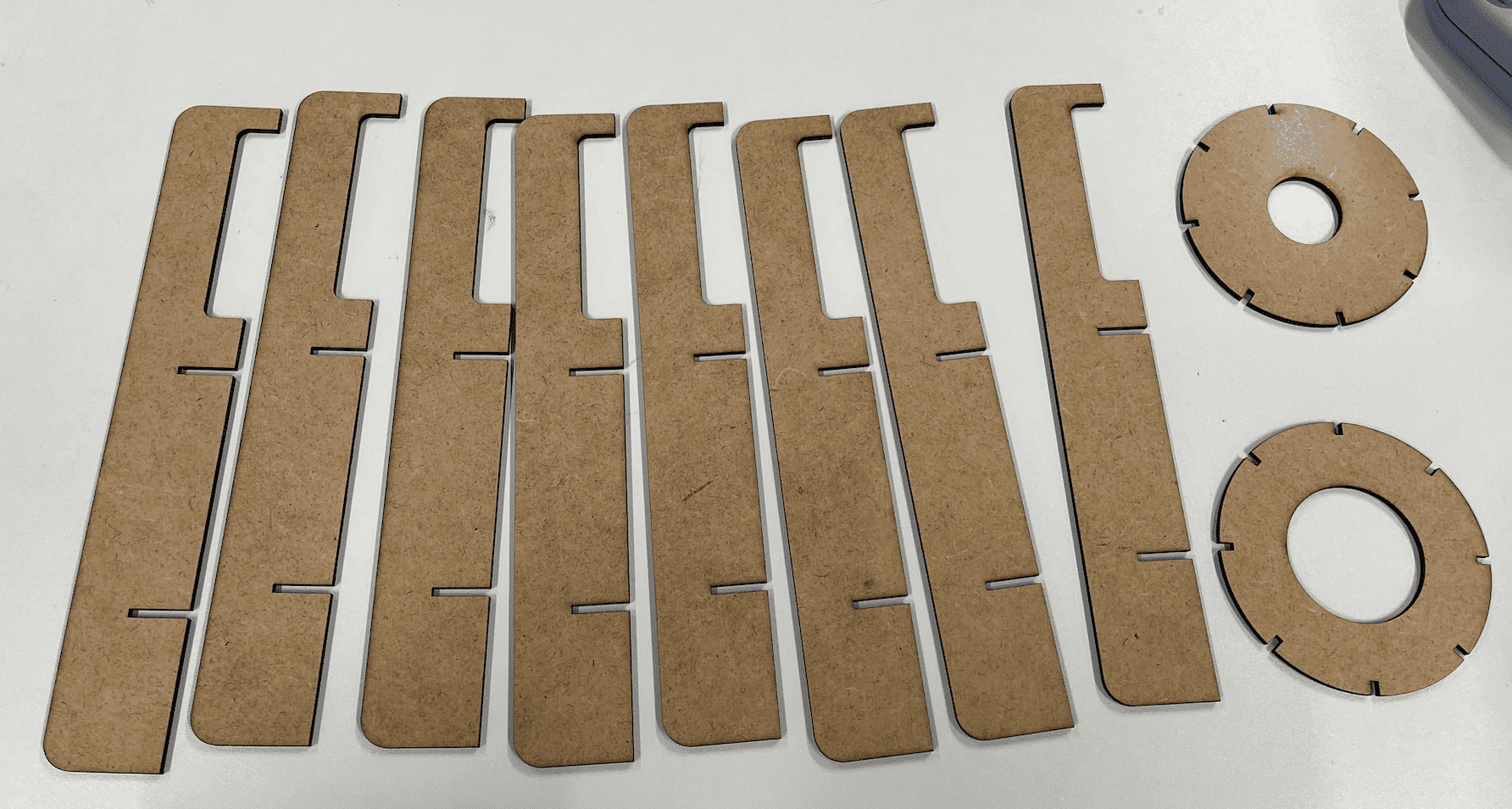
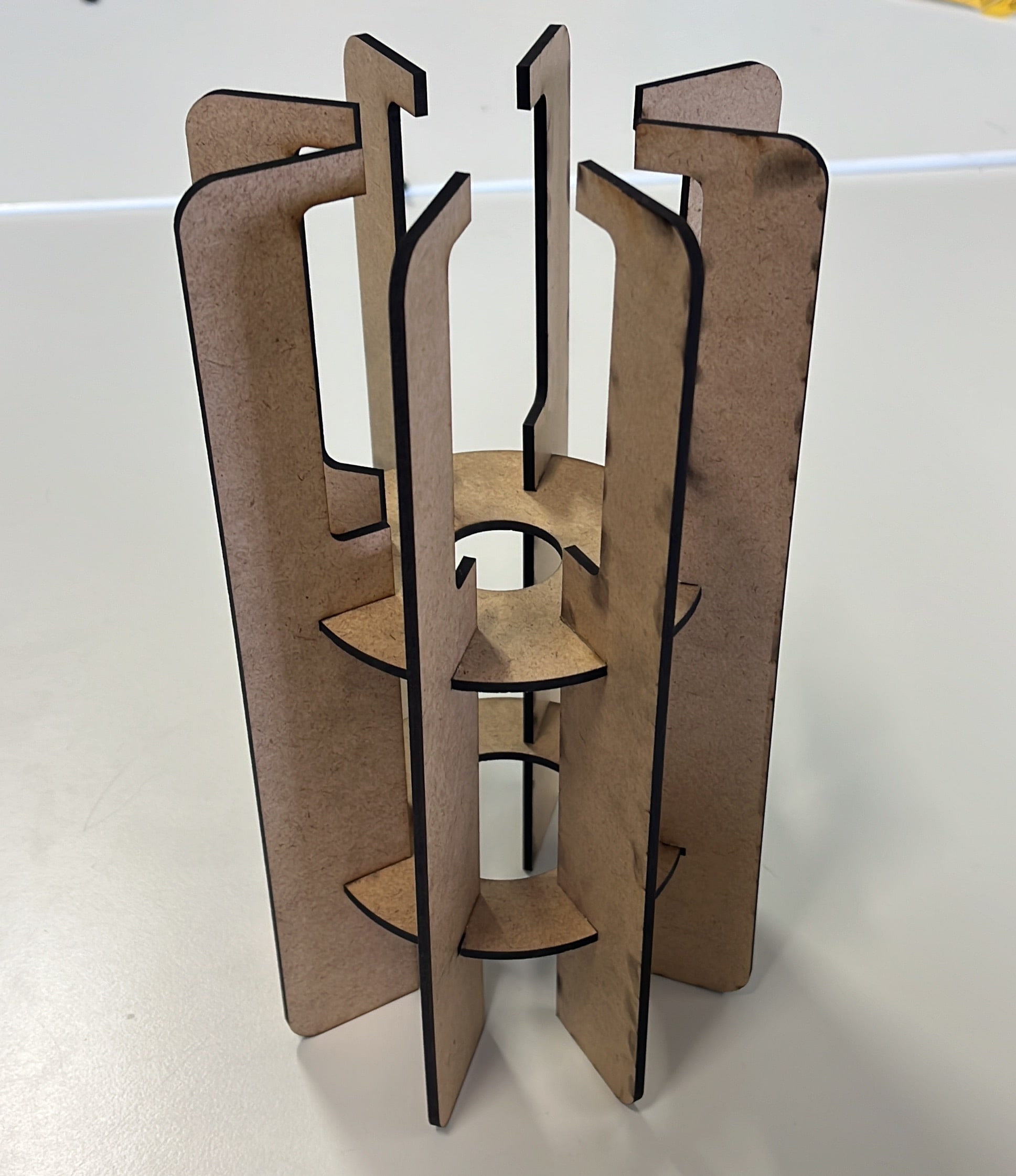
When finished cutting, I took out the pieces from the machine. The fit tolerance of laser cut parts worked quite well as we did in the group assignment. I didn't have to sand to put the pieces together and there was no loose fit that would cause the product to move.
I assembled all the pieces easily and here is my design.