
Week 12: Input Devices
Building on the progress of my Electronics Design Week, I am now going to design an additional board that connects 4 more hall sensors to the ESP32-S3 and update the interface so that it knows to display the right image for each tile in the grid.
Designing and Milling Two New Variations of the Archiblox Board:
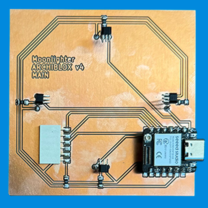
The Microcontroller Board
This board will be identical to the orginal board with the exception that it now has a 6 pin connector that utlizes the additional inputs on the board to read the second array of 4 hall senors on the auxillary board.
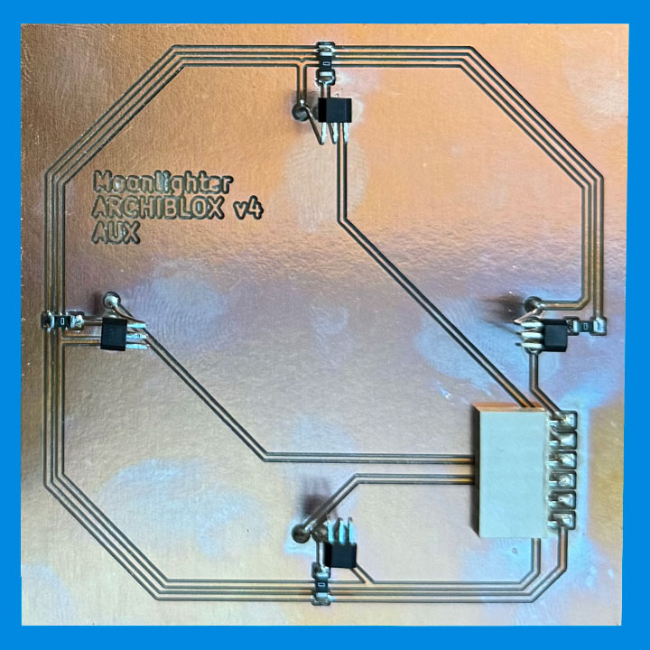
The Auxillary Board
This board will not have its own microcontroller, it will only connect the four hall sensors to a 6-pin connector.
Connectivity
The two boards will be connected using male-to-male wires from the 6-pin connector on the Aux Board to the 6-pin connector on the microcontroller board.
Updating the Code to Read 2 Tiles
With the help of ChatGPT once again, I uploaded the original code and asked it to help me generate the appropriate python code to read an additional array of 4 hall sensors using the specific identified pin on the ESP32-S3.
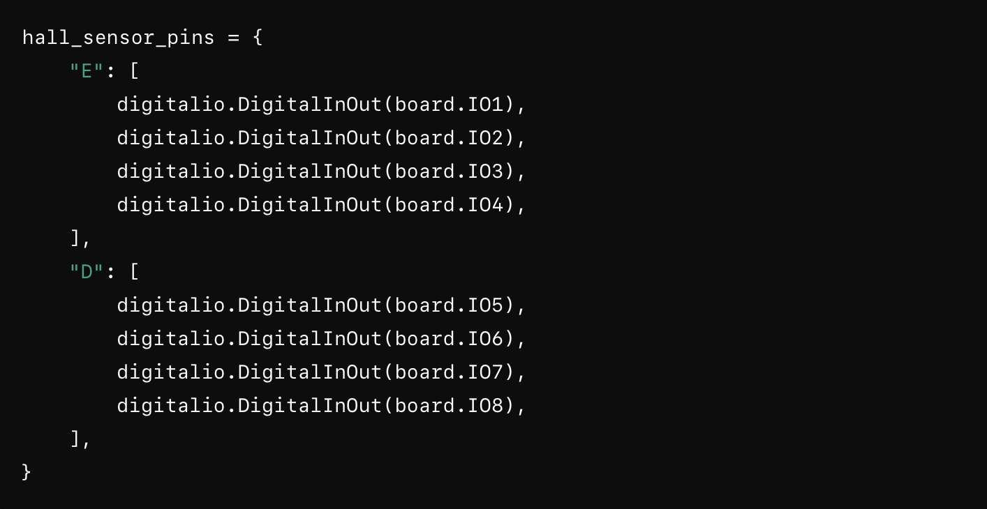
It suggested creating Hall Array Sets identified by a unique letter:
# Set up the Hall sensor pins
hall_sensor_pins = {
"E": [
digitalio.DigitalInOut(board.IO1),
digitalio.DigitalInOut(board.IO2),
digitalio.DigitalInOut(board.IO3),
digitalio.DigitalInOut(board.IO4),
],
"D": [
digitalio.DigitalInOut(board.IO5),
digitalio.DigitalInOut(board.IO6),
digitalio.DigitalInOut(board.IO7),
digitalio.DigitalInOut(board.IO8),
],
}
Here you see that it establishes one board Hall Effect Sensor array as "E" and the other as "D"
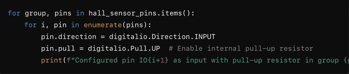
The rest of the code establishes the same criteria of reading the hall sensors and displaying it on the screen:
# Configure each pin as input with a pull-up resistor
for group, pins in hall_sensor_pins.items():
for i, pin in enumerate(pins):
pin.direction = digitalio.Direction.INPUT
pin.pull = digitalio.Pull.UP # Enable internal pull-up resistor
print(f"Configured pin IO{i+1} as input with pull-up resistor in group {group}")
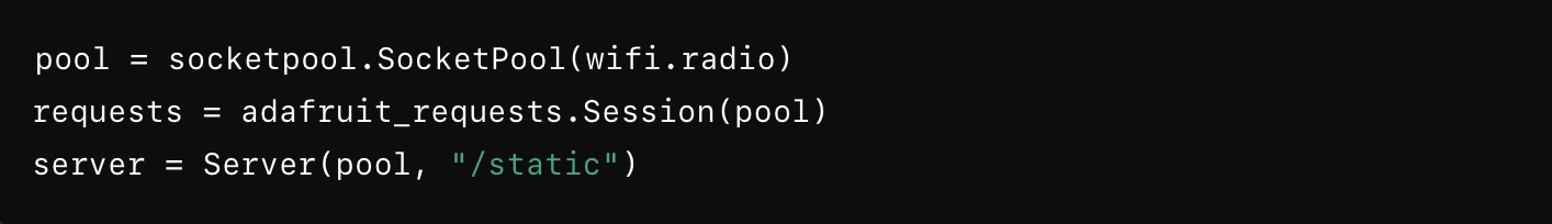
# Initialize the server
pool = socketpool.SocketPool(wifi.radio)
requests = adafruit_requests.Session(pool)
server = Server(pool, "/static")
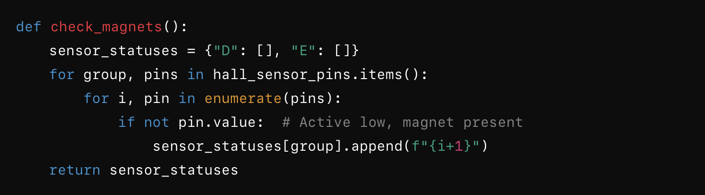
def check_magnets():
sensor_statuses = {"D": [], "E": []}
for group, pins in hall_sensor_pins.items():
for i, pin in enumerate(pins):
if not pin.value: # Active low, magnet present
sensor_statuses[group].append(f"{i+1}")
return sensor_statuses
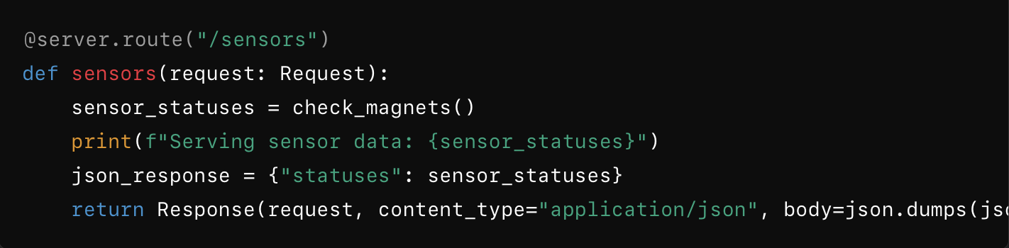
@server.route("/sensors")
def sensors(request: Request):
sensor_statuses = check_magnets()
print(f"Serving sensor data: {sensor_statuses}")
json_response = {"statuses": sensor_statuses}
return Response(request, content_type="application/json", body=json.dumps(json_response).encode('utf-8'))
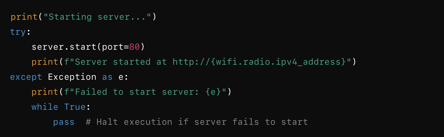
print("Starting server...")
try:
server.start(port=80)
print(f"Server started at http://{wifi.radio.ipv4_address}")
except Exception as e:
print(f"Failed to start server: {e}")
while True:
pass # Halt execution if server fails to start
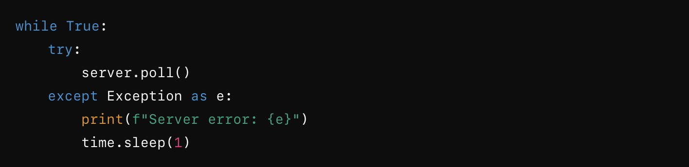
while True:
try:
server.poll()
except Exception as e:
print(f"Server error: {e}")
time.sleep(1)
Breaking Down The Code:
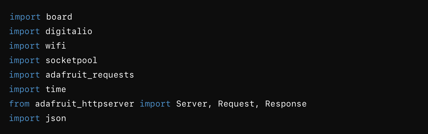
Importing Necessary Libraries
Here, we are importing various libraries that help interact with the hardware (like pins and WiFi) and handle HTTP requests and responses.
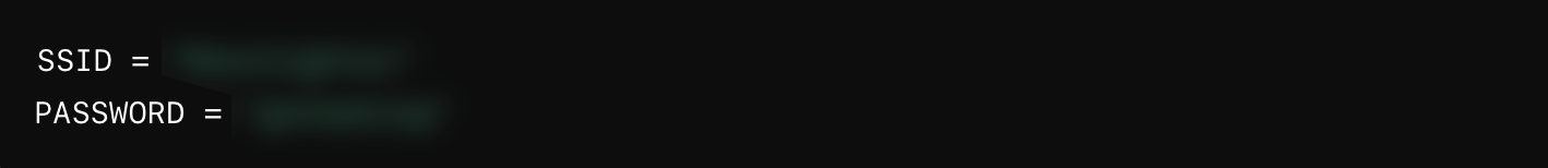
WiFi Configuration
The SSID and PASSWORD variables are set with the WiFi network's name and password. You'll replace these with your actual WiFi credentials.
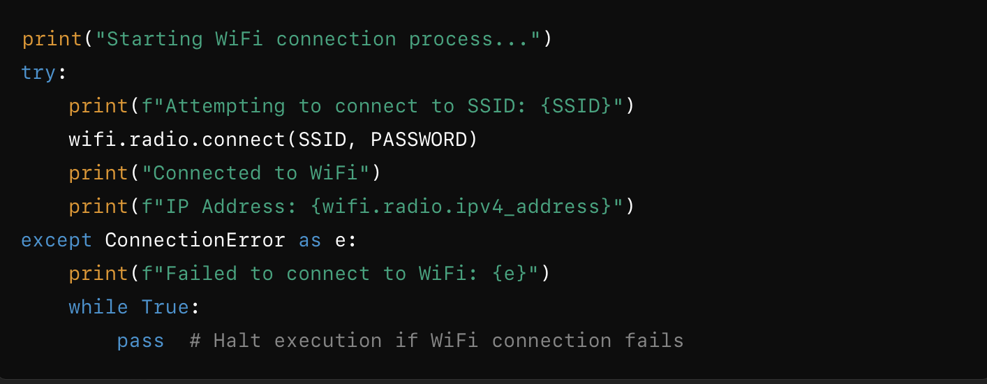
Connecting to WiFi
This block tries to connect to the specified WiFi network. It prints messages to indicate the connection status. If the connection fails, it prints an error message and halts execution.
Setting Up Hall Sensor Pins
The hall_sensor_pins dictionary maps sensor groups "E" and "D" to specific pins on the board.
Configuring the Pins
This loop configures each pin as an input with an internal pull-up resistor, ensuring the pins are ready to detect sensor signals.
Initializing the Server
These lines initialize the network resources required for the server. 'pool' handles socket connections, 'requests' manages HTTP requests, and 'server' sets up the HTTP server.
Defining the Magnet Check Function
This function checks the status of the hall sensor pins. If a magnet is present (active low), it adds the pin number to the corresponding group in the sensor_statuses dictionary.
Defining the Route for Sensor Data
This route handles requests to "/sensors". It checks the magnets' statuses, prints the statuses, and returns them as a JSON response.
Starting the Server
This block starts the server on port 80 and prints the server's IP address. If the server fails to start, it prints an error message and halts execution.
Main Loop
The main loop keeps the server running, constantly polling for incoming requests. If an error occurs, it prints the error message and pauses for a second before continuing.
This updated 'archiblox.py' code sets up a WiFi connection and an HTTP server on a XIAO ESP32-S3 microcontroller. It reads data from two sets of 4 hall effect sensors and provides the sensor status via a web API. The server runs continuously, responding to HTTP requests with the current status of the sensors.
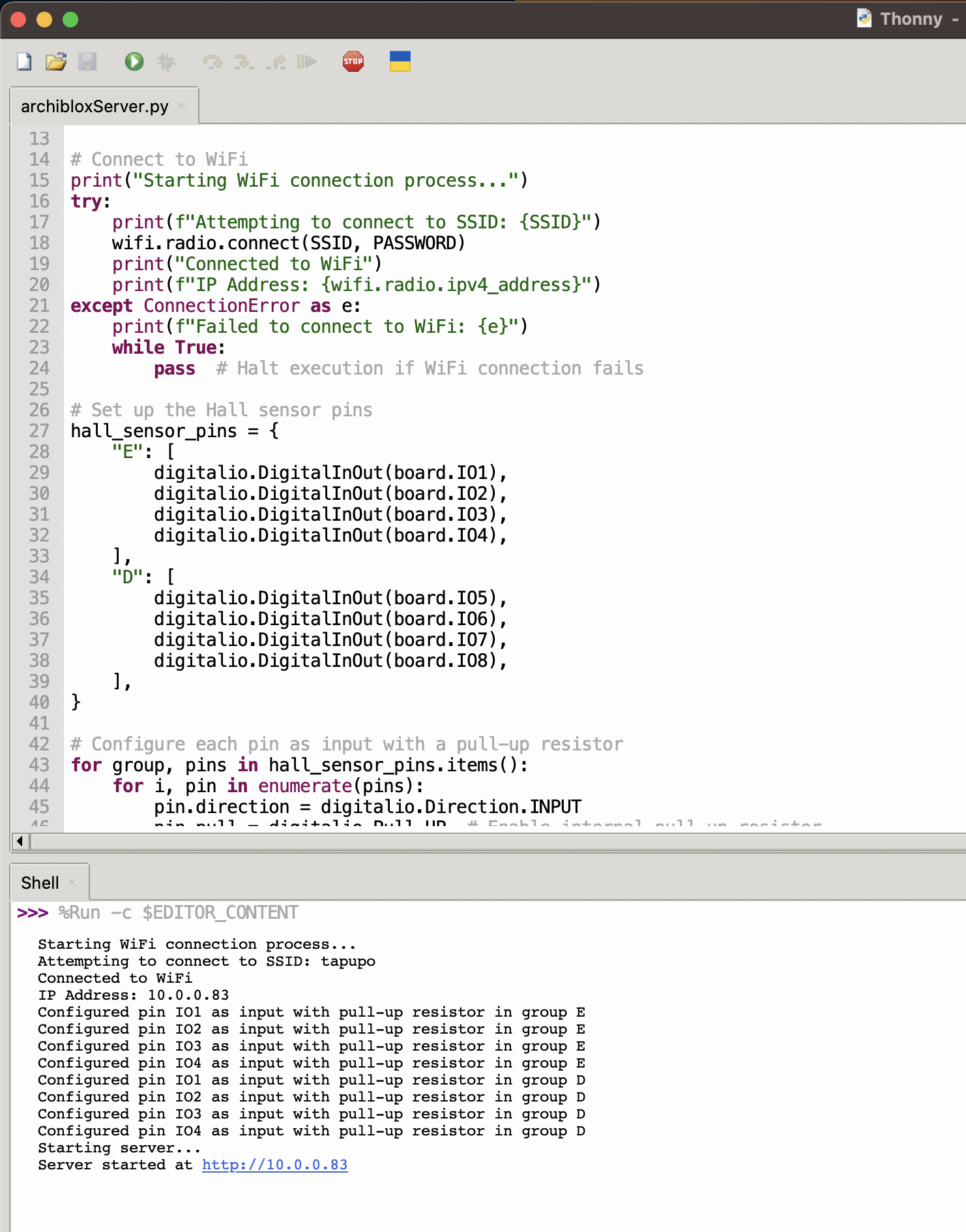
Testing the Hall Effect Sensor Input Signal
Thonny has a readout of everything the boards sensors are triggering, displayed in the console. As I placed various magnet tiles on the sensor array, they displayed the appropriate readout in the console.
Files
Download New Main Board Design
Download New Aux Board Design
Download New Microcontroller Code
Group Assignment
In this week's group assignment, we are tasked with probing an input device(s)'s analog levels and digital signals.
We will test my hall effect sensor digital input and Peter's Distance Sensor I2C input on the oscilloscope.
The Hall Sensor
The Hall sensor behaves like the LED from our probing of the microcontroller earlier. When a magnet is present, it just outputs a value 3.3V and when no magnet is present, it just outputs zero.
Hall Sensor Probe
The Distance Sensor
The distance sensor working in I2C is a stranger readout. It outputs an indiscernable signal with peaks and valleys. It is nothing like the PWM of the servo that week. We tested both the Data and Clock pins on that and the same output occured.
Distance Sensor Probe
These results showed us there are simple and complex input devices in these embedded circuits and it can be difficult to discern them. These were run with no code, just using the milled circuit as a power and ground source to run the modules.
Copyright 2024 Thomas Pupo - Creative Commons Attribution Non Commercial
Source code hosted at fabcloud/fabacademy/2024/thomas-pupo