3D Robotic 3D Printing and Scanning
This week’s goal was to model and 3D print as well as scan an object. I explored the possibility of merging these tasks by using a robot arm to manually scan a surface in Blender, by moving the robot to different positions and reading the TCP location and then generating a point cloud from that data. Using this scanned surface then generating the 3D printing (3DP) toolpaths with Blender Geometry Nodes, leveraging attributes as explained in week 3.
Objectives
- 3D scan a surface using a robot.
- Develop 3DP toolpaths in Blender.
- 3d print on the scanned surface.
- Blender for modeling and toolpath generation.
- KukavarProxy for robot communication.
- KUKA KR10-R1100 robot.
- Animaquina: A custom addon for robot toolpathing (Made by me :)).
- Massive Dimension Pellet Extruder for 3D printing.
- Adafruit QTPY ESP32 for controlling the extruder steps.
Process
The KR-10 robot, equipped with KukavarProxy, allows for near real-time communication. I wrote a Python script to read the robot’s TCP position and generate a marker in Blender, digitizing points to create a mesh/surface. This script was linked to a Blender UI button for easy operation, updating the virtual robot’s armature via Blender’s IK solver. This process helps have an accurate posititon of feautres in the cell relative to the robot. Simplifing calibration.
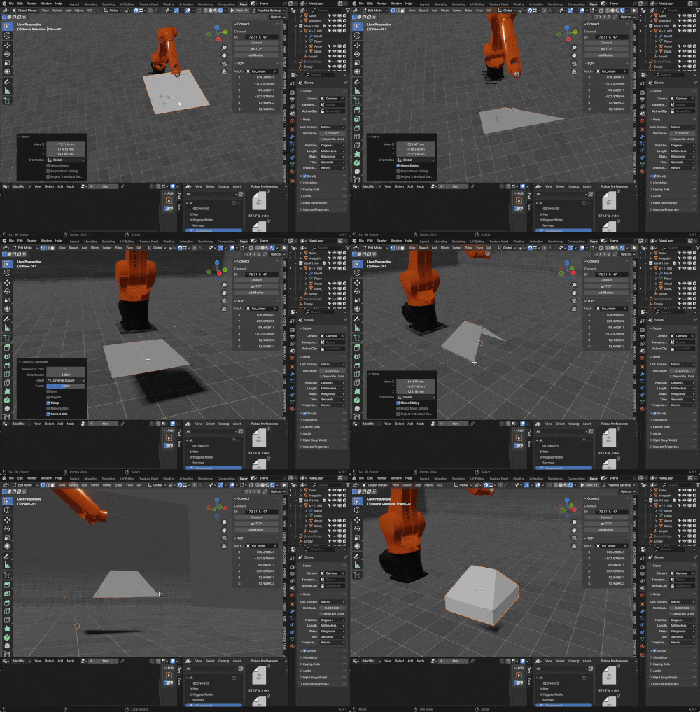
I first digitized a table surface as a base by jogging the robotwith the pendant to each of its four corners and adding a digital marker (an empty in blender) with the UI button , generating a point cloud to identitfy the corners, then i created a plane that uses this four points to effectibly reflect the surface in the 3D world.
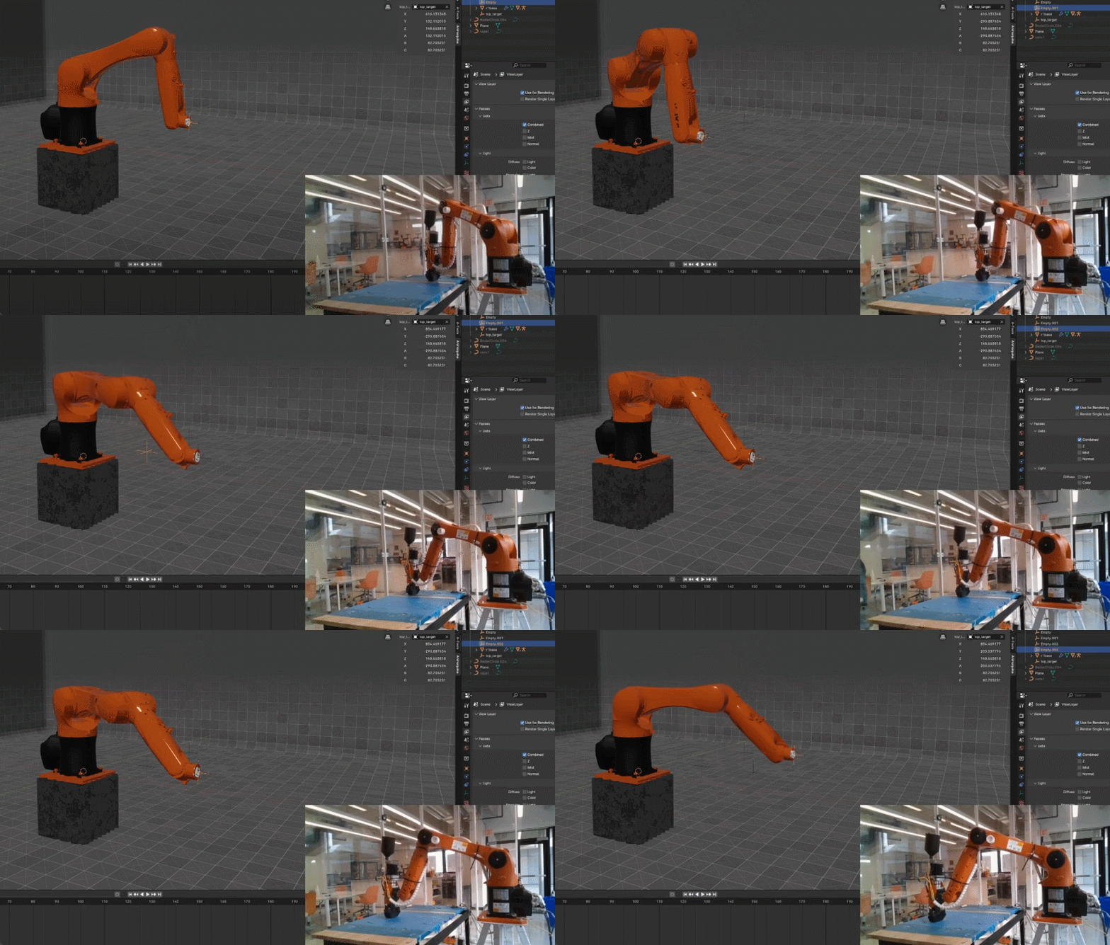
Then, I mapped a printing bed that was not parallel to the base, this bed is a flat wood surface with random positioning and orientation just to probe that this method simplifies the process of 3D printing with a robot:
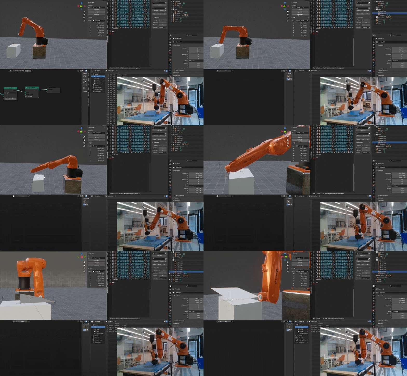
Using a hand-drawn bezier curve on the place, I sampled the curbe into points (or targets) and repeated in the Z-axis (geometry nodes), Using the script I was able to export this targets it into KRL code for 3D printing, employing the same strategy as the week 3 laser cutting project:
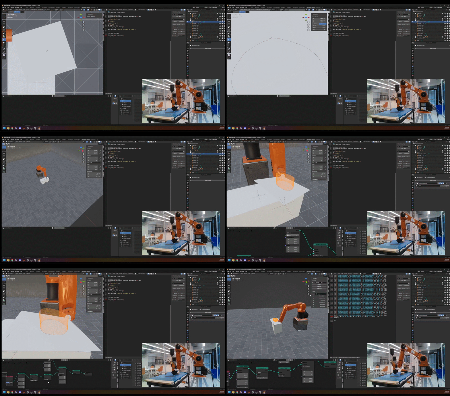
Here’s the result:

Gallery
Scanning
Here is a more complex pointcloud from a scanned surface using this method:
First I connect the robot to Animaquina using the robots IP address
Now I can read the the current TCP of the robot by pressing the get TCP or add marker button.
First using the teach pendant I move the robot into each of the corners of the object at each point, once im close to it I click the add marker that adds a point in blender on the 3D view :
Here you can see all the points that we just mapped:git
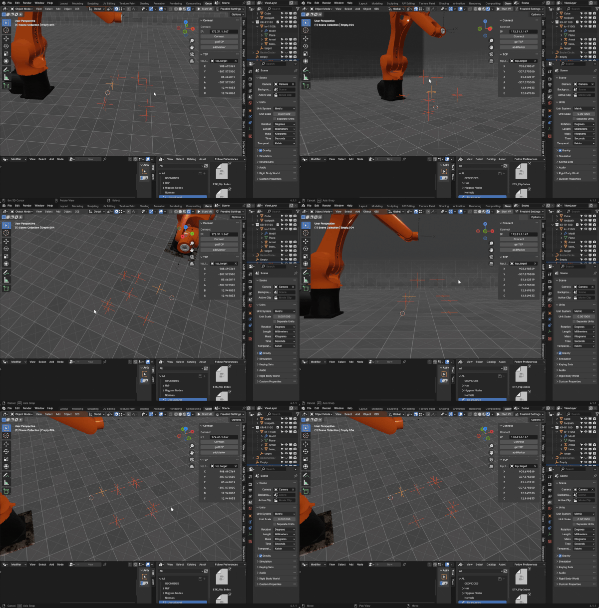
Now I can use blender mesh modeling by adding a plane, subdividing it and snapping them to the scanned points.
Conclusion
Despite initial challenges, such as selecting the correct robot tool and base and mistakenly using a model with a different reach, the interactive toolpathing workflow showed promising potential. While the final object was simple, this workflow demonstrates the feasibility of 3D printing on non-standard surfaces—a task challenging for other manufacturing methods. The possibility of adding material on top of something that is already existing is intresting there are no straight foward manufacturing methods to do this. I think this can be used for mass cutomization, for isntance fabricating something with standard fabrication and adding a cutomized component.
Files