Week07 Group Assignmnet - Testing the CNC Machine
Shopbot
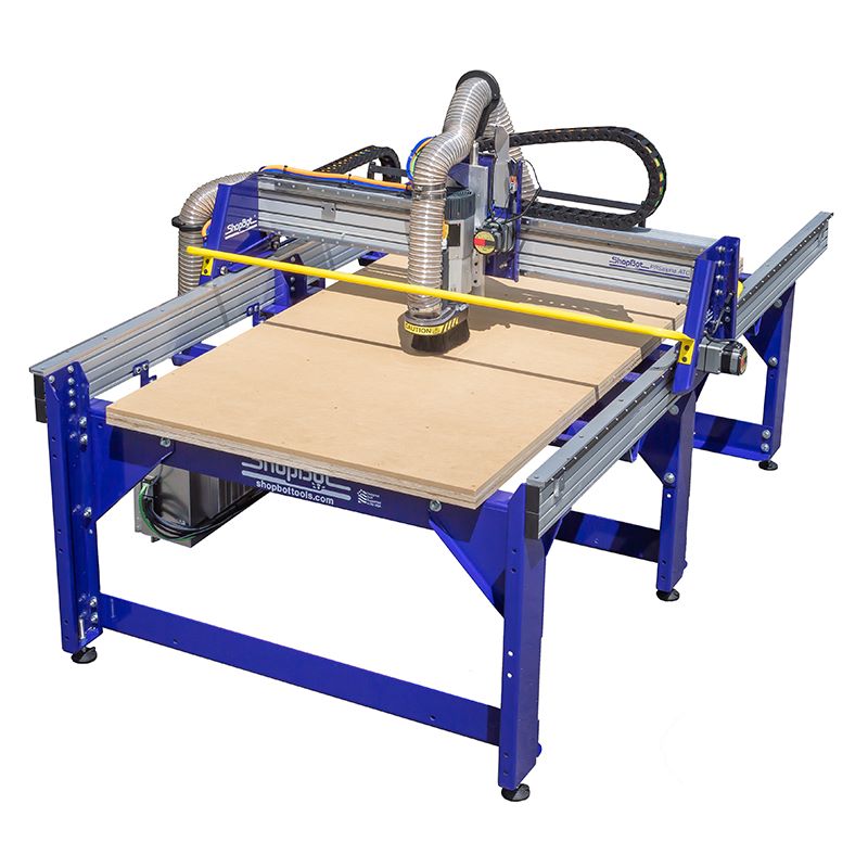
The machine we used for large format cutting is a ShopBot PRS5 Alpha.
On the Shopbot product support page, there are lots of documentations for the machine. The Quick Start Guide featured on the page provides the basic instructions for using the machine.
Specs
The PRS5 Alpha comes with several different size of working area, the varient we use is a "120 – 60" model, which has the specs listed below:
| Footprint | 3660mm x 2310mm x 1700mm |
| Cut/Movement Area | 3225mm x 1550mm x 200mm |
| Weight (machine only) | 90 – 113kgs (depending on options) |
| Crated machine | 1422mm x 1150mm x 965mm (77-105kgs) |
| Collets | Includes 1/4″ and 1/2″ ER25 Collets (1 each) |
| Max Cut Speed | 300mm per second |
| Max Rapid Speed | 750mm per second |
| Positional Resolution | 0.01mm |
| Electrical Requirements | 120VAC 15Amps for motors; 220V Single Phase, 230V Three Phase or 3880/460V Three Phase for spindle. |
Making the test file
To test the machines precision and kerf size to produce the optimal joint, we first did some testing to find the best numbers for the configuration.
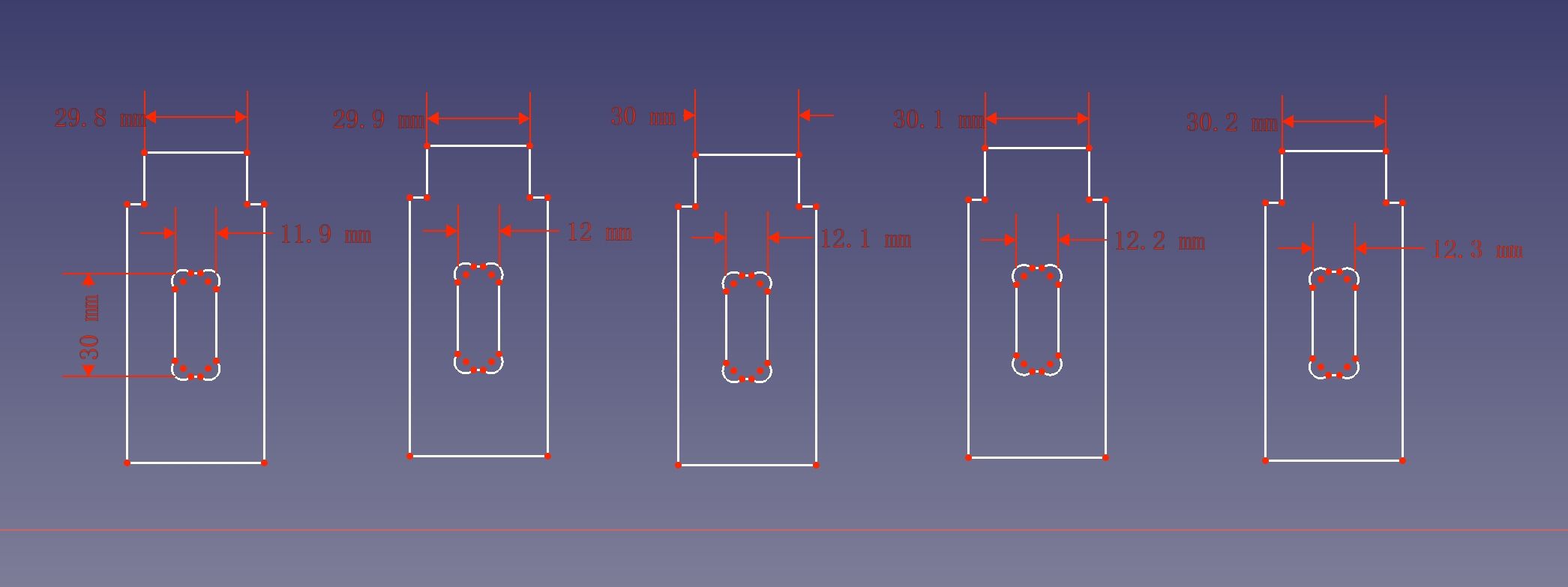
We used FreeCAD to sketch some test pieces that can be joined by inserting them into each other, and we varies a little bit for the width of the slots and the joints to see which one of them fits the best.
The board we used were 12mm plywoods, and we cut them with a 6mm end mill, so we set the slot width from 11.9-12.3mm, the length for the joint from 29.8-30.2mm for a 30mm long slot, with 6.5mm dimeter dogbones in the corner as shown below:
Then export the sketch as a DXF file. The test files we used can be found in the Project files section at the bottom of the page.
Tool path generation with VCarve
The software we used for generating the tool path for the machine is Vectric VCarve Pro. As it stated by Shopbot, the software is included with every new Shopbot purchased.
-
First open the exported DXF file in VCarve and in the
Job Setuppane, set theJob Sizeto the corresponding size and thickness to the board that we are cutting.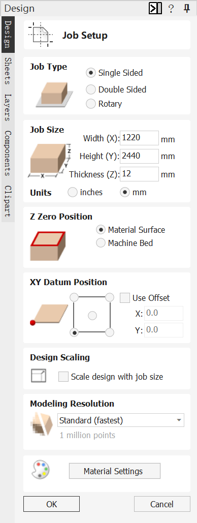
-
Then use the
Move Selected Objectstool in theTransform Objectssection and place the piece at appropriate position, make sure to leave some gaps between the piece to let the end mill pass.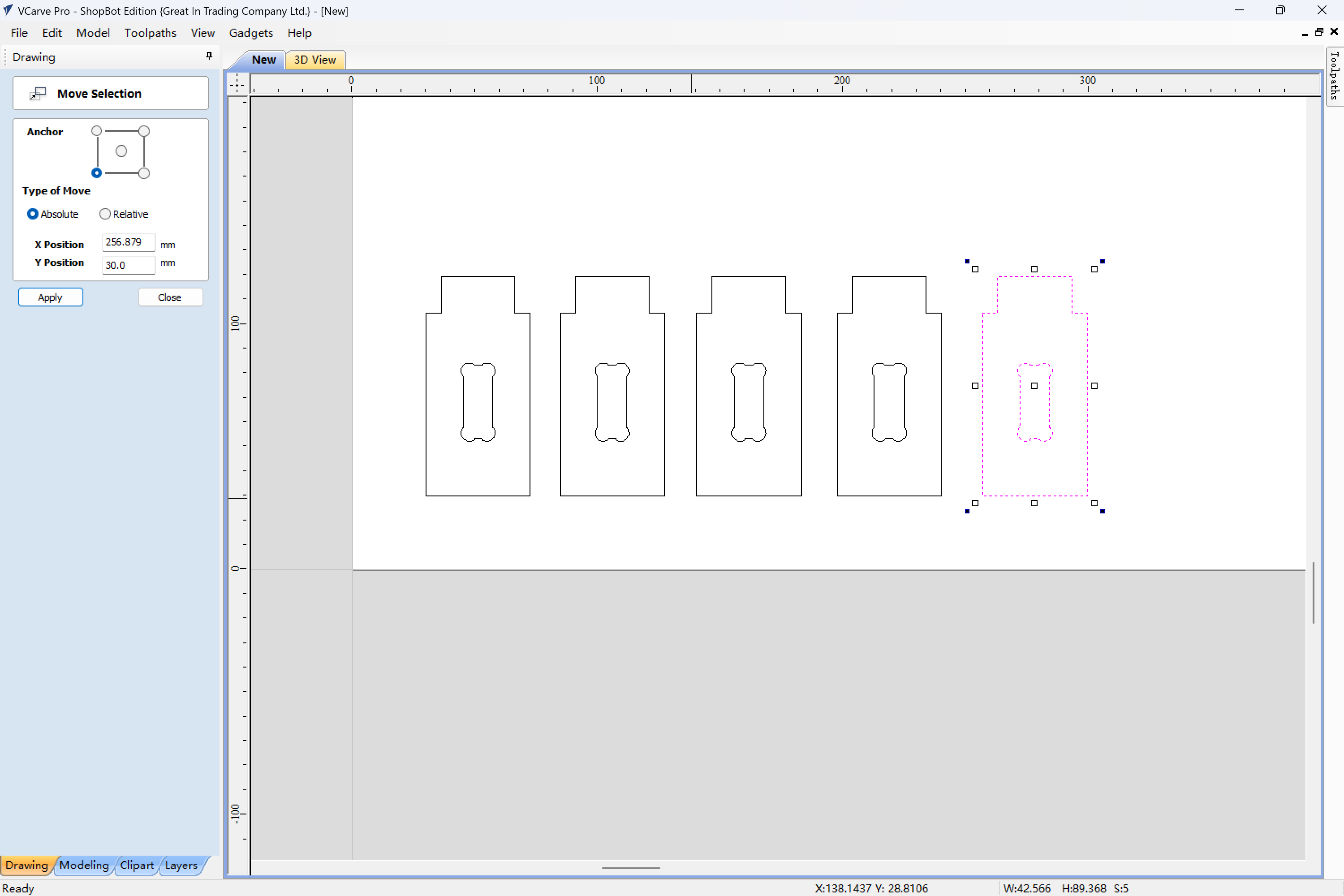
-
Select
2D Profile Toolpathin theToolpathspane on the right. In theCutting Depth, setStart Depthto0andCut Depthto12.5mm, because we want the piece to be cut through.Then in the
Toolsection, clickEdit Passes..., and set the passes to2to make the board be cut in two passes.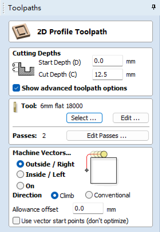
-
Then click
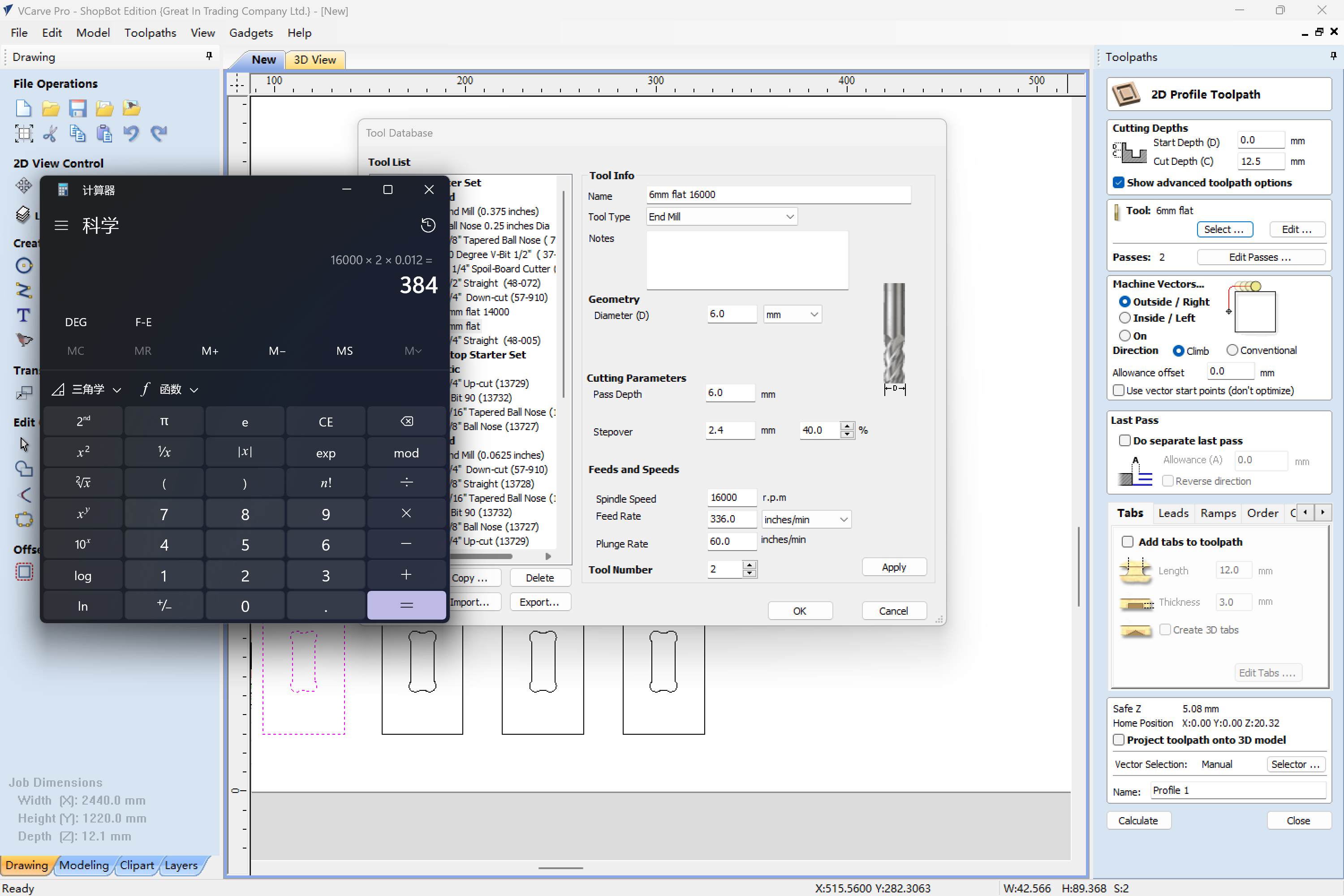
selectin theToolsection. In the openedTool Databasepanel, add a new tool that's a 6mm end mill.To set the feed rete and other parameters for the tool, we need to calculate it from a useful number called chip load, which is the thickness of material removed by each cutting edge during a cut.
And the
chip loadcan be defined as the formula below:$$ CHIP\ LOAD = \frac{FEED\ RATE\ [INCHES\ PER\ MINUTE]}{RPM \times NUMBER\ OF\ FLUTES} $$
Base on the formula, we can calculate the feed rate for our end mill based on the chip load and the number of flutes.
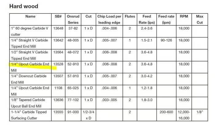
The end mill we're using is a 6mm upcut with 2 flutes. According to the table shown for hard wood cutting, it has the chip load of 0.006-0.008. So we can calculate the feed rate for the tool like so:
$$ CHIP\ LOAD \times RPM \times NUMBER\ OF\ FLUTES $$
which equals \( (0.006 \times 2) \times 16000 \times 2 = 384\ inches/mm \)
-
After setting the parameters for the tool, in the
Tabsat the bottom, checkAdd tabs to toolpath, hitEdit Tabs...button and add tabs in the drawing to hold the pieces in place.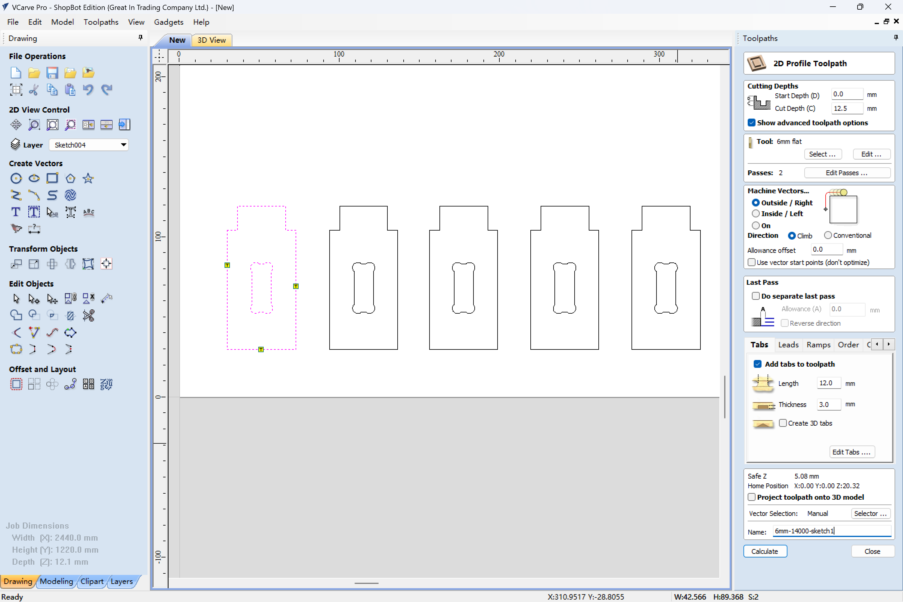
-
Now in the
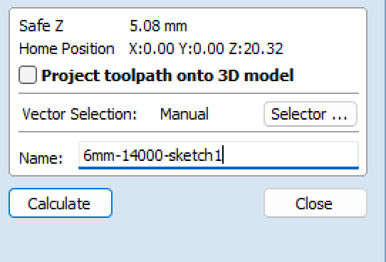
Machine Vectors...section, first selectOutsize/Right, and select the outlines of the pieces in the 2D view. Then in the bottom section, set theNamefor the generated tool path and clickCalculate.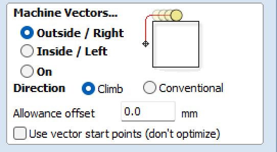
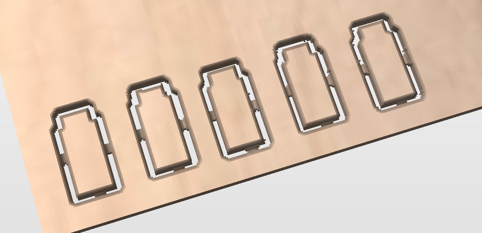
In the preview window, check to see the tool path is correct and make sure the material is cut through.

-
Then generate the tool path for the inner slots the same way but use the
Insideoption forMachine Vectors.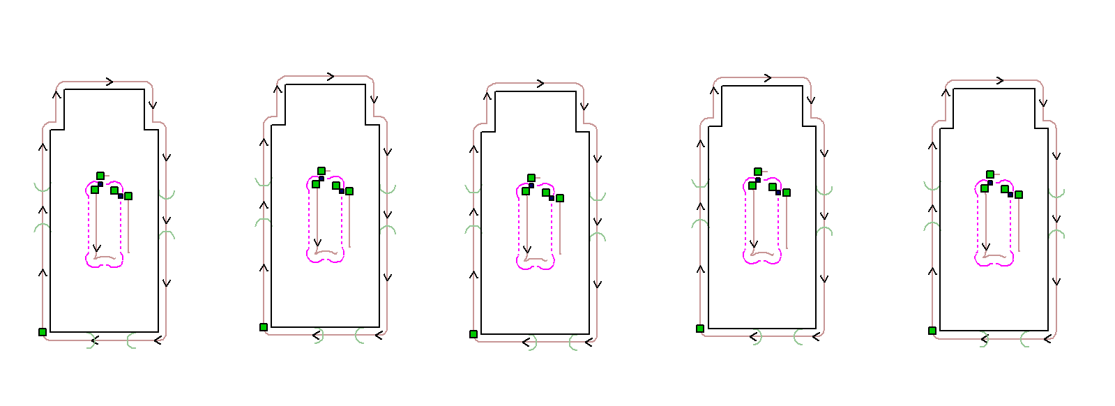

-
After that, click
Save Tool Pathand the tool path is exported.
Operating the Machine and Cutting the Test Pieces
Before cutting, first use the vernier caliper to measure the board's thickness in some different spots, make sure its not too uneven or off too much. When generating the path, we can use an average of the measured thickness to set the cut depth more appropriately .
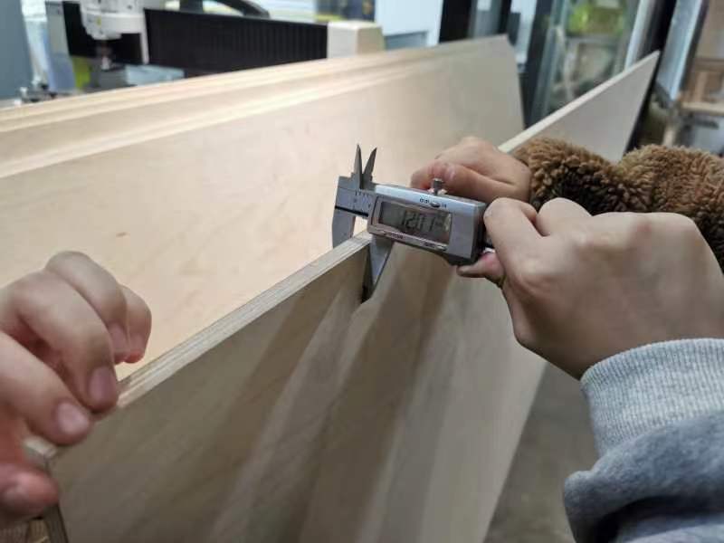
The board we are using is a 12mm plywood board, which was measured about 12.02mm in various places.
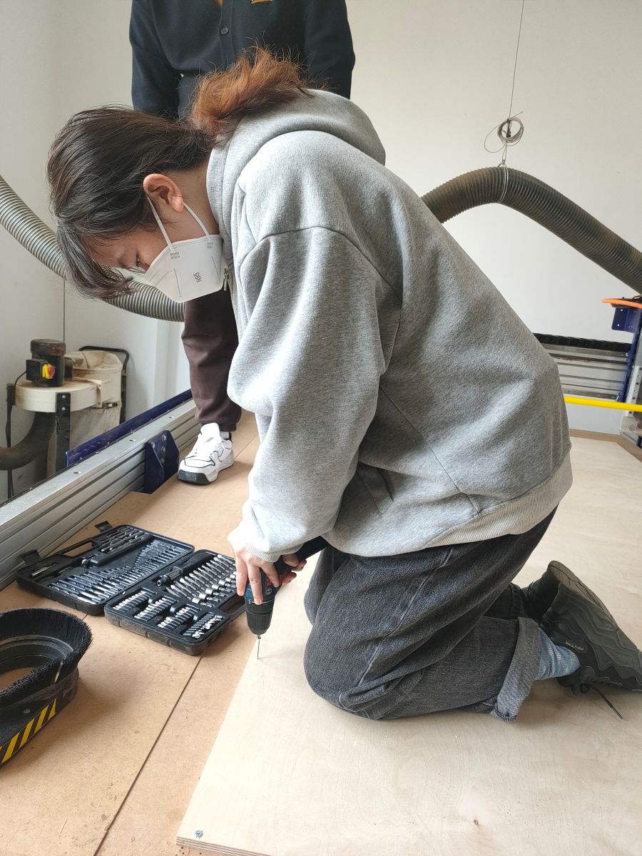
Then move the gantry out of the way and keep it fixed on the sacrificial layer below. We were using screws to install the board.

The important point when driving screws with a drill is to keep the body and the arms in a straight line to apply the force straight down.
Then check the control box on the side, the red switch is the emergency stop switch which cuts off all the power in the system when switched off. The power switch next to it is the power for the main router. Switch it to the "Engaged" state with the key to turn on power for the router before start cutting.
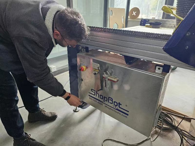
The wrenches sticked to the magnets next to the power switch is for changing the collet and tool bits.
We used a 6mm end mill with a shank diameter of also 6mm to cut, and with the 1/4" ER25 collet to hold it.
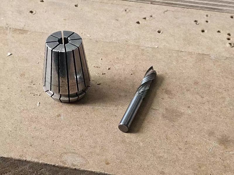
After changing the tool, use the wrenches to lock the nut tight.
Then use the control software to move the X and Y axes to the bottom left of the
board cutting area and use the Zero Axes button to set the XY zero for the
machine work coordinates.
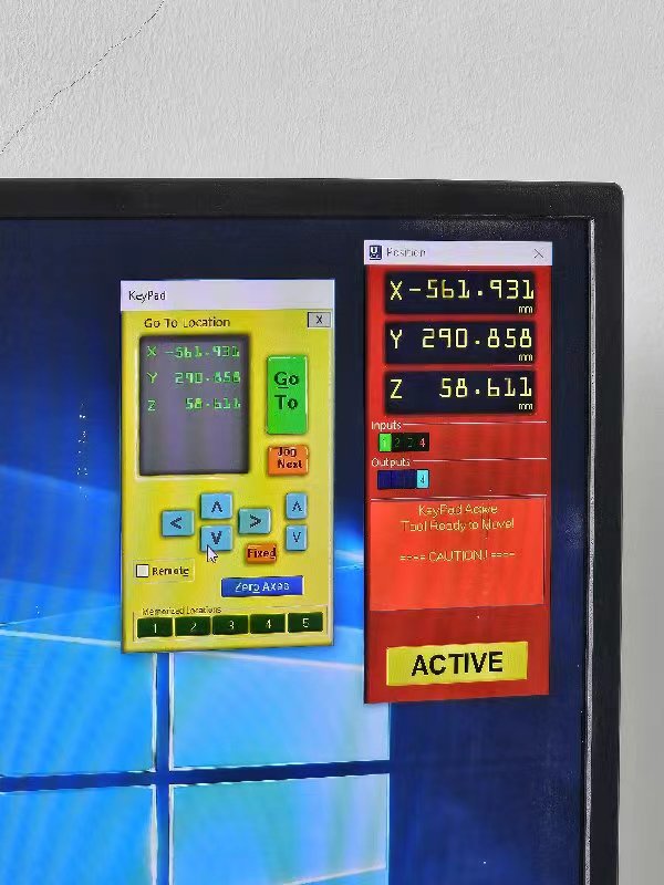
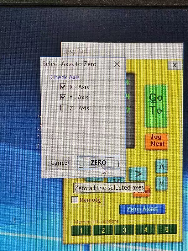
Then put the plate for zeroing the z axis under the end mill and clamp the clamp
on to the end mill, then select Z - Axis in the Zero Axes menu. The z axis
will slowly move down and stops when it touches the plate. The z-zero is then
set.
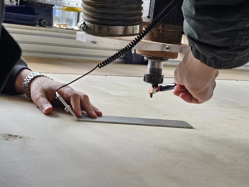
After that, in the control software, open the Spindle Control panel, check the
speed for the main router, and adjust it using the panel on next to the machine
control box.
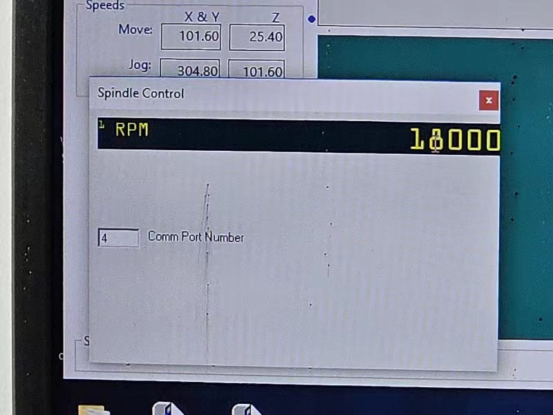
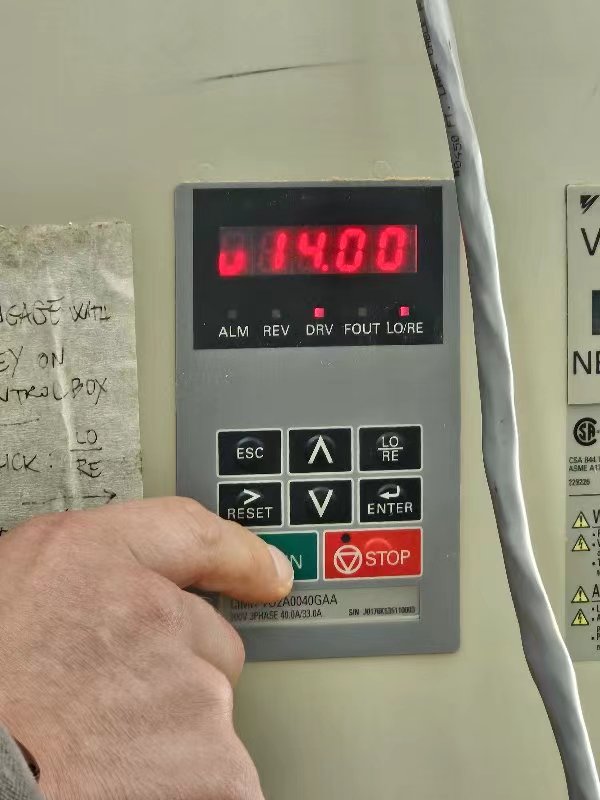
The spindle speed we set to is 16000rpm.
Put the sweeper of the vacuume around the spindle, then it's time to upload the tool path and start cutting.
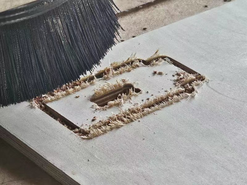
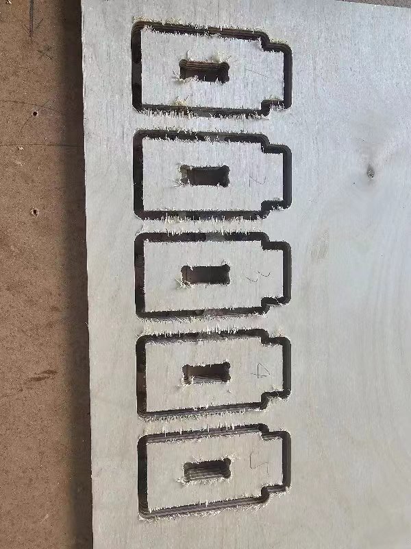
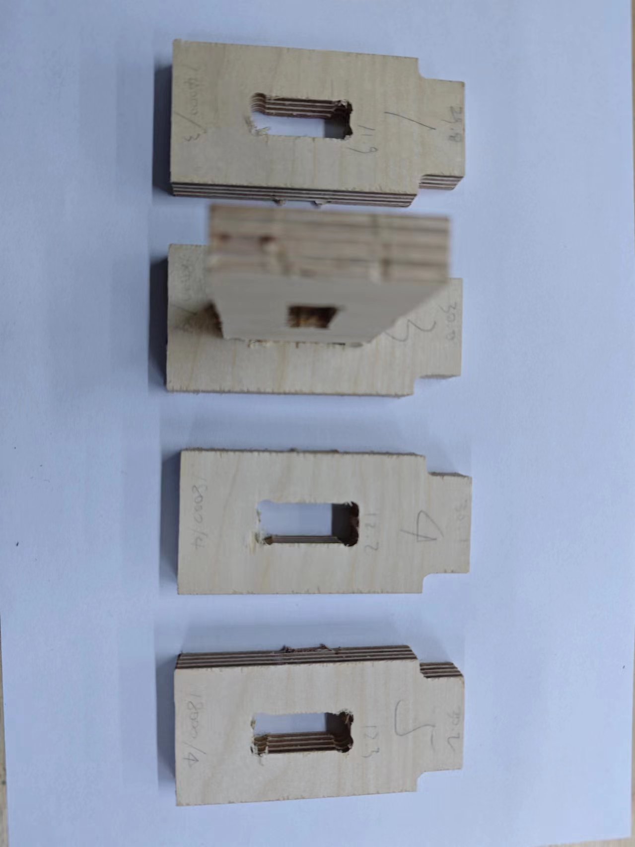
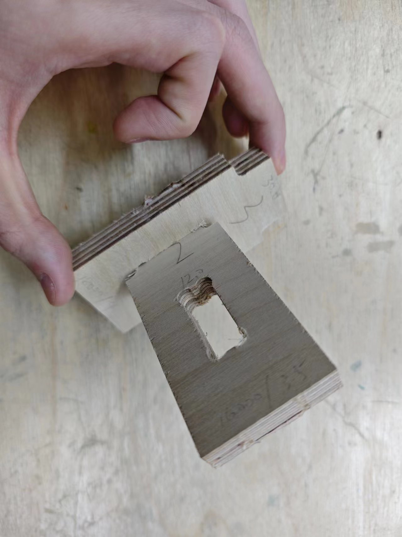
After the test pieces were cut and sanded, we tried to insert them into each other, and the best joint is +0.1mm offset in both the length and the width of the slot.
Project files
- Machine test files:
- FreeCAD project file: test-pieces.FCStd
- DXF file: test-pieces-Sketch.dxf