Group assignment
In our fablab this year, our students’ various projects are mainly based on the I2C communication protocol. In this assignment group, we’ll be focusing on this communication protocol.
Overview
I2C (Inter-Integrated Circuit) is a widely used serial communication protocol that allows multiple devices to communicate with each other over a shared bus. It was developed by Philips Semiconductor (now NXP Semiconductors) in the early 1980s and has since become a standard for interconnecting integrated circuits.
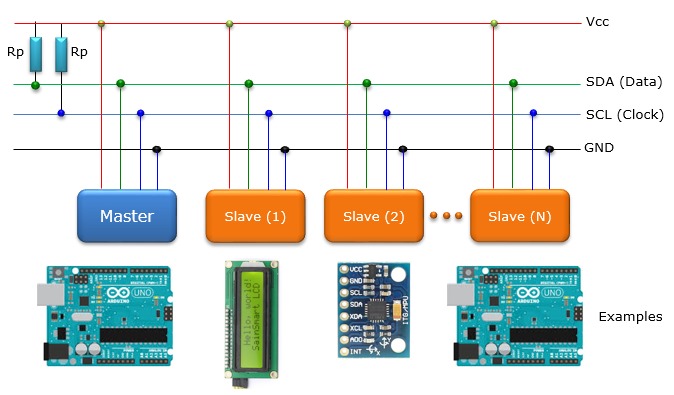
The I2C protocol uses two wires for communication: a data line (SDA) and a clock line (SCL). These lines are bidirectional, allowing devices to both send and receive data. Each device on the bus is identified by a unique 7-bit or 10-bit address.
In I2C communication, one device acts as the master, which initiates and controls the data transfer, while the other devices act as slaves. The master device generates the clock signal and controls the timing of the data transfer.
The communication process involves two main operations: addressing and data transfer. To address a specific slave device, the master sends a start condition followed by the slave address. The addressed slave then responds with an acknowledgment (ACK) signal.
Data transfer can occur in two modes: write mode and read mode. In write mode, the master sends data to the slave by transmitting a series of bytes. The slave acknowledges each byte received. In read mode, the master requests data from the slave, which then transmits the requested data back to the master.
I2C supports multiple data transfer speeds, typically categorized into standard mode (up to 100 Kbps), fast mode (up to 400 Kbps), fast mode plus (up to 1 Mbps), and high-speed mode (up to 3.4 Mbps). These speeds can be adjusted based on the capabilities of the devices on the bus.
The I2C protocol offers several advantages, including simplicity, ease of use, and the ability to connect multiple devices using only two wires. It is commonly used for communication between various components in embedded systems, such as microcontrollers, sensors, actuators, and other peripheral devices.
In summary, I2C is a widely adopted communication protocol that provides a straightforward and efficient way for devices to exchange data, making it a popular choice for many applications in the embedded systems domain.
Here’s an illustration of the architecture

I2C Scanner
Before we start with the I2C, we need to get/know the addreses of the various devices. we will be talking about and using the I2C Scanner for this purpose.
The I2C scanner is a simple program that can be executed on an Arduino to detect and identify I2C devices connected to the I2C bus. Here’s how it operates:
The code for the I2C scanner starts by including the Wire library, which provides the necessary functions for I2C communication. The setup function initializes the serial communication at a specified baud rate, and the loop function is where the I2C scanning process takes place.
In the loop function, the program iterates through all possible 7-bit I2C addresses (from 0 to 127) and sends a start condition followed by the address using the Wire library’s “beginTransmission” and “endTransmission” functions. If a device acknowledges the address, it means that a device is present at that address. The program then prints the address to the serial monitor, indicating the presence of an I2C device.
The I2C scanner code is a useful tool for identifying I2C devices connected to an Arduino. It helps verify the correct connection of devices and their assigned addresses. By examining the output on the serial monitor, you can determine the I2C addresses of the connected devices and use them in your further programming and communication tasks with those devices.

Master & Slave Boards
After finding the addresses we will now have a Master(primary) board and a Slave(secondary).
Master
In I2C communication, the master plays a central role by initiating and terminating communication with the slaves, generating the clock signal (SCL), and addressing the slaves it wishes to communicate with. The master controls the flow of data, sending data bits and receiving acknowledgement bits to ensure correct transmission. In systems with a single master, management is straightforward, but in multi-master configurations, arbitration mechanisms are required to manage conflicts.
Slave
The slave responds to the master’s requests, waiting for start-up conditions and the address sent by the master to begin communication. Each slave has a unique address on the bus and, once addressed, sends or receives data according to the master’s commands. It must manage acknowledgement bits (ACK/NACK) to confirm correct data reception. The slave cannot initiate communication, but must be ready to respond to commands and transmit requested data.
Now the operation of I2C is based on Primary-Secondary (master-slave) communication. The microcontroller acts as a master, controlling data flow to attached secondary (slave) devices. Each secondary (slave) device has a unique address assigned, allowing the primary (master) to select which device it wishes to communicate with.
Programming
For the programming, we decided to set up an I2C communication between the project of our student “Jonathan” and that of “Edem”.
To do this, we used Jonathan’s input board, which you can find here, and Edem’s output board, which you can also find here.
Here you can see :
an image of the input board

the output board

the robot to be operated

an overall image

In our case, the Input board is the Master and the Output the Slave.
The input board has a motion detector, and the output board has a servomotor that drives a robot. When the sensor detects movement, the servomotor receives a signal and starts to drive the robot.
Code
Master

Slave
