Introducing BeeLine Tracer
In sewing and tailoring, precision and efficiency are key to creating quality garments. Tailors and dressmakers often use tailor’s chalk to mark and draw lines on fabric before cutting. This is often a demanding task for tailors working with complex patterns or mass-produced orders, where repeatability and precision are essential. To make things easier for these craftsmen, we decided to design a digital machine that uses chalk to help tailors trace shapes on the fabric, which will certainly simplify and speed up the cutting process. By automating this task, you could potentially reduce human error and increase production efficiency.
Called “BeeLine Tracer”, this machine was inspired by Quentin Bolsee’s Beehive project. Unlike Quentins project, which is designed for use with 8020 extrusions, we wanted to modify it so it could work with square tube because it is more readily available on the local markets for African labs. This required an entire redesign with inspiration taken from Beehive’s modularity and drive system. Hence the system is named “Beeline” in honor of the original Beehive concept. This will reduce the need to import parts, and consequently cut the cost of the machine. BeeLine Tracer is made from square tube galva and fishing wire, replacing extruded aluminum and belt. It also features Nema motors, PLA and ABS filament, Arduino and CNC shield. For now, BeeLine Tracer will be used to draw on paper, and will help us refine the controls and program for the next version.

Hero Shots
Construction
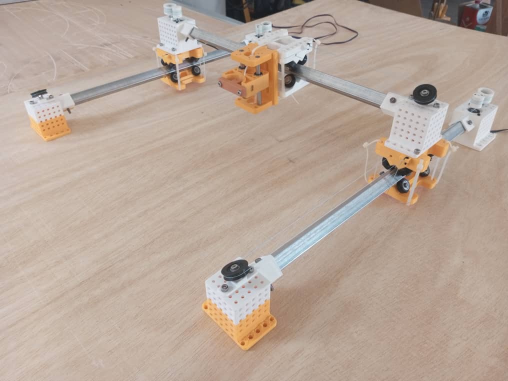
Our machine has 3 axes: x, y and z. In this section, we’ll talk about the design of each axis, from 3D modeling to assembly. We’ll also look at the electronics and the complete assembly of the machine, as well as the various tests.
CAD Designs
For 3D modeling, we mainly used Fusion 3D and FreeCad. Here are a few screenshots.
X & Y - Axis
The X and Y axes are made from the same parts.


Z - Axis
Sub-assemblies
This section deals with the assembly of the various axis.
X & Y - Axis
After printing the various parts, here’s the assembly with our square galva tube


Z - Axis
Z axis parts and assembly.


Electronics and Programming
We used Arduino/CNC sheild, nema 17 motors and the UGS (Universal Gcode Sender) platform for machine control.


