10. Machine design
Process
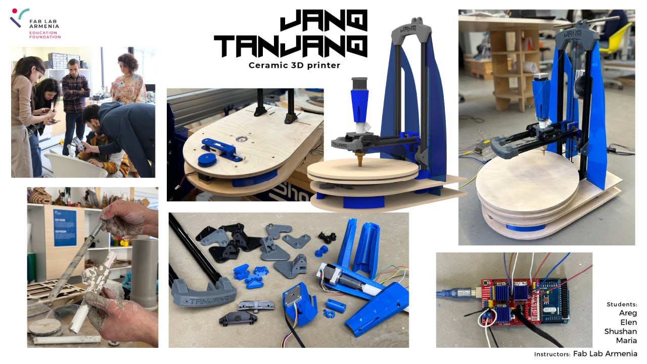
In this week we decided to do Ceramic 3D Printer.
And first of all we brainstormed and find the motion concept .
It turned out printer with turntable and radial axis.
First we sketched the table mechanics using trust ball bearings that fortunately stayed from my previous project.

As I am an artist and also sculptor , we decided that I must do the extruder.

And I did lots of experiments , and this is what we have in outcome.
The ceramic 3D printer extruder with an auger works as follows:
- Material Loading: The ceramic paste is loaded into the extruder container.
- Auger Mechanism: The auger (screw) inside the extruder rotates, moving the ceramic paste forward. In our case, the auger is a wood drill bit.
- Extrusion: The paste is dispensed through the extruder nozzle, which in our case is a pipeline component, specifically a reducer.
This process allows for the control of material flow and its even distribution, which is especially important for the precise fabrication of ceramic products.
After that, when we were sure that it would work, we divided the work among ourselves. My main role was the project management , mechanical design , modeling and etc. Also I did CNC and laser cutting and assembling . But the most important thing is that I had to make sure that all the parts developed by Elen and Maria separately could be assembled and there were no inconsistencies.
So Maria designed the turntable.
More information about this can be found on “Machine-Building” in Maria’s documentation.
And I helped her with the mechanism and designed the belt tensioner.

And so at first I designed a two-way tensioner because I thought that in this case we would have more maneuver for adjustment. But it turned out that one-sided ones are better.

Of course, I broke the first printed part, but this was only because I went too far with the rigidity, because this part had to be not only rigid, but also springy, and to solve this problem I reduced the wall thickness.

So on the second try it came out very well and mechanism worked perfectly.
And so After all this, we decided to do a preliminary build and make sure that everything works and if there are any problems, then solve them at an early stage. We assembled the table and also assembled the extruder using an extruder holder designed by Elen.

Elen did Z and Y axises.
More information about this can be found on “Machine-Building” in Elena’s documentation.
And finally I took the two mechanisms and tryed to combine them into one.
 and for that I designed lot of mounts for v slot because in that time I thought that our main problem would be the Z axis strength, I also changed motor mount and complete the design of base for cnc cutting

And when I designed the holder for the motor, it turned out that it was larger than the support of the car and I didn’t want to increase the support, so I made grooves in the plywood and installed the motor in it, thereby reducing the distance between the two plywoods.

I further modified the mount for the extruder to attach the work to the axis, adding ears with a hole for attaching to the mount.

And after all we complete our machine design and add the acrylic parts for construction and beauty and also added the text “JANQ” it means (effort) .

And finally It looks very nice.

Parts Production
Since we did the design and the manufacturing process itself at the same time and this happened throughout the week, unfortunately we forgot to take videos and photos of the processes. I just have this photo from the latest version of milling the plywood bace.

Testing
Throughout the week, Shushan and Mkhitar were engaged in testing and with the video they were able to automate the extruder feeding.
Table automation
Maxim also helped a lot in developing the program, but you can find out more about this on the Shushan’s Machine Building week .
Time to Assemble.
We assembled and disassembled many times. And every time we improved the constuction and solved the bugs.

After the last assembly, we found out that the extrusion is very heavy and the motor is weak and cannot lift such a weight. And so we decided to make a counterweight to the extruder and for this we designed and 3D printed a shaft holder using which we attached a thread on which we hung the counterweight.
Possible Improvements
- Using more powerful motors - will solve the problem that we have regarding the weight of the extruder in the future
- Improved durability Y-axis - because there is a lot of load hanging on it and it tilts a little.
- Replacing some parts with metal ones - In this situation, we can reduce the size and parts but at the same time with a more durable construction.
- Metal container. - add metal container with compression for storing and supplying clay.
Conclusion
I consider this project a success because our team tried their best. And I think that we managed to properly distribute the work among ourselves. True, our main goal was training and for this we would have to do what we don’t know, but I must say that this week was different from the rest in that we all gathered for one goal, and everyone wanted our car to be the best the best. And that’s why we distributed the work so that everyone could do what they do best. True, we did not have time to complete the work, and there is still work to be done. The main problem I think is that we didn’t have time and we had to act in a hurry and we made a lot of mistakes cause of lack of experience. Anyway I think our team did great work and it will work perfectly.
Source files
Click for downloading
JANQ Ceramic 3D Printer CAD
Tensioner
Extruder
Bace Mountings and wooden part for CNC