Group assignment:
Here is our group assignment
Test the design rules for your 3D printer(s) Document your work on the group work page and reflect on your individual page what you learned about characteristics of your printer(s)
Individual assignments
Design and 3D print an object (small, few cm3, limited by printer time) that could not be easily made subtractively 3D scan an object (and optionally print it)
Identify the advantages and limitations of 3D printing Apply design methods and production processes to show your understanding of 3D printing. Demonstrate how scanning technology can be used to digitize object(s)
Linked to the group assignment page
Explained what you learned from testing the 3D printers
Documented how you designed and 3D printed your object and explained why it could not be easily made subtractively
Documented how you scanned an object
Included your original design files for 3D printing
Included your hero shots
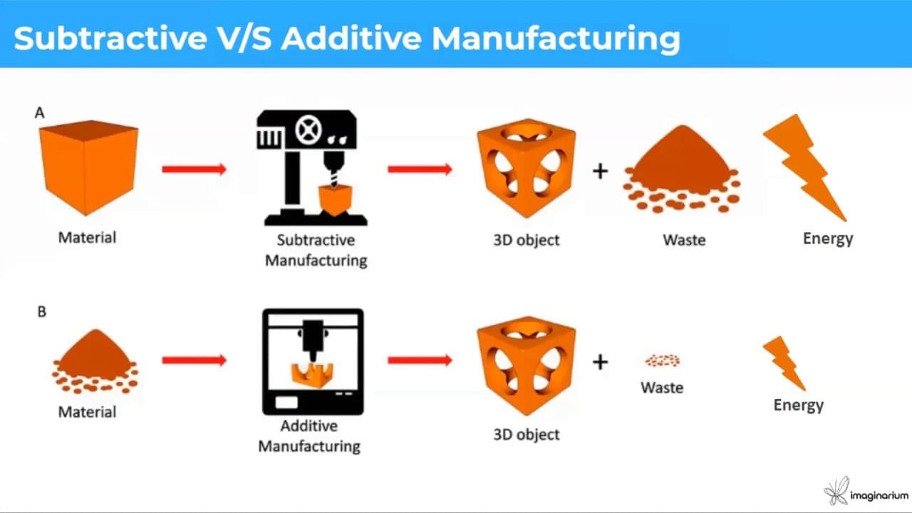
Here is the basic difference between additive and subtractive manufacturing:
Additive manufacturing builds objects layer by layer, minimizing waste and enabling complex designs, while subtractive manufacturing shapes objects by removing material, making it more suitable for mass production but less flexible in customization.
Let's DIVE deeper!
Additive Manufacturing:Additive manufacturing, which also is known as 3D printing, builds objects by sequentially cross-sealing and layering from digital 3D models. This means reducing waste during fabrication and making for easy tweaking of common, non-critical elements, but precise for expensive or rare materials. It has a high capacity to design complex shapes and geometry including internal structures and organic architecture. It is convenient with less time loss due to minimal tooling changes only after it is ready to start printing. Additive manufacture highly adaptive to production customisations and small batches, consequently giving a flexibility for special or personalized items without incurring digressing margins.
Subtractive Manufacturing:During subtractive manufacturing forming objects is achieved by removing material from the block of an originally solid item using some machining methods like, milling or turning. It generates waste as the overlayer of material, including excess pieces, is being knocked away thereby giving rise to the cost-raising issue and environmental concerns. Though it is quite exact, subtractive manufacturing process might be less beneficial than additive manufacturing in some aspects such as the production of complex internal geometries or intricate forms. Technological build-ups are time-consuming, including an extensive range of diverse tooling, fixtures and technical parameters for all designs. Subtractive laser cutting is most effective for mass-production, but requiring changes to the designs or making special items may get complicated and costly.
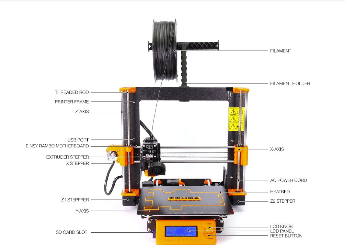
The Prusa i3 MK3 distinguishes itself as a great 3D-printing machine due to its user-friendliness, its perfect design, which lets your print better and the self-calibration feature which makes it the ideal selection for multiple creative tasks.
Here is a labeled illustration of the Prusa i3 MK3.
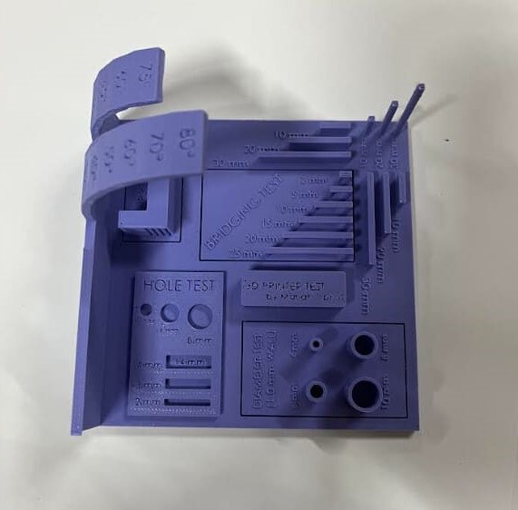
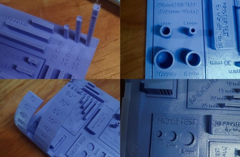
Our evaluation leads us to the searching for that there is an obvious reduction in security along with print high quality as the elevation of the published item rises. In addition, we observed a steady wear and tear in efficiency when the printing angle surpasses 60 levels especially noticeable at angles around 80 levels. Furthermore, we kept in mind a decrease in the security of the top part of the linking examination with enhanced size. In spite of these obstacles general efficiency continues to be adequate.
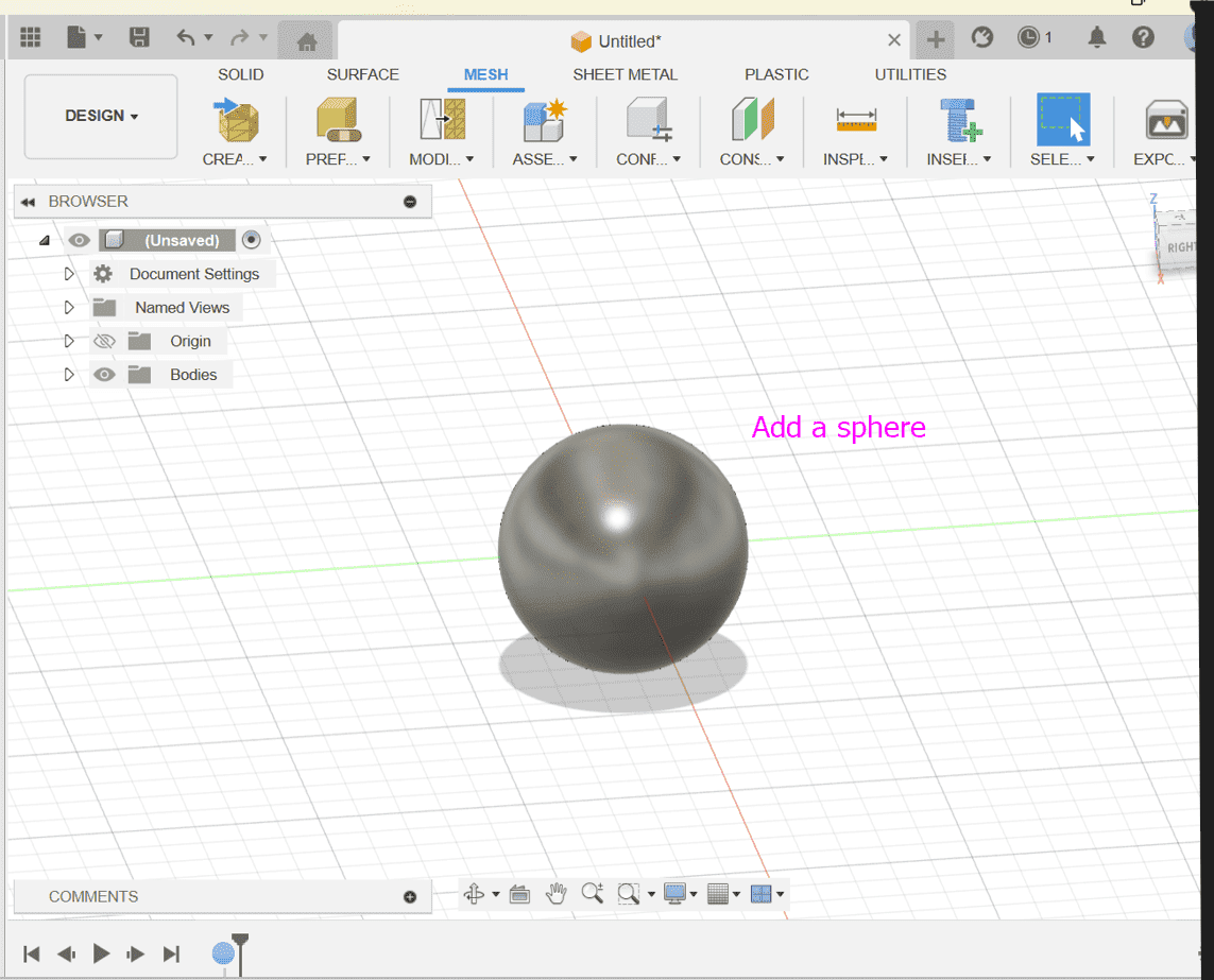
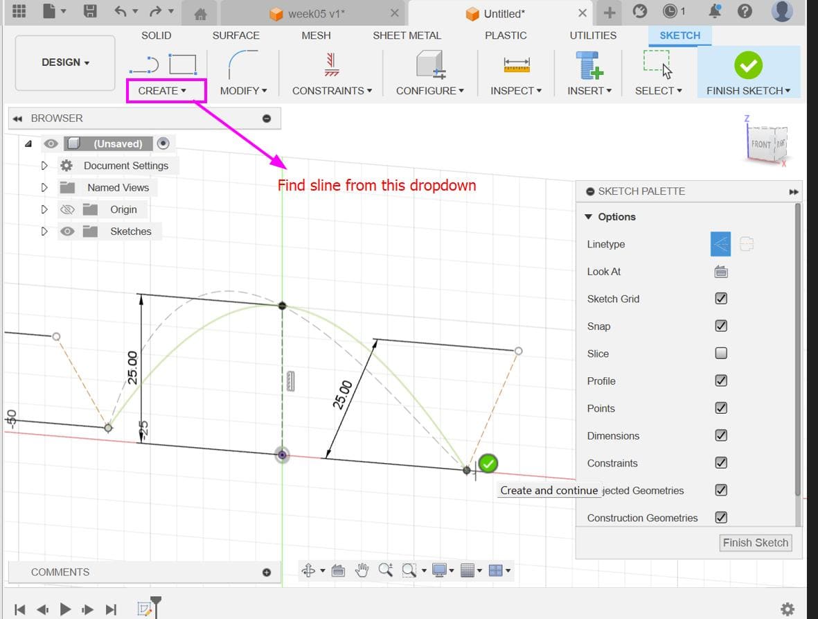
For the individual assignment, I referred to this YouTube video on how to make a voronoi sphere in fusion 360.
Add Sphere: Create a sphere by going to surface > create > sphere in Fusion 360. This will serve as the base geometry for the Voronoi-like pattern.
Add Mesh: Insert a mesh onto the sphere's surface. This mesh will be used to define the pattern of the Voronoi-like cells.
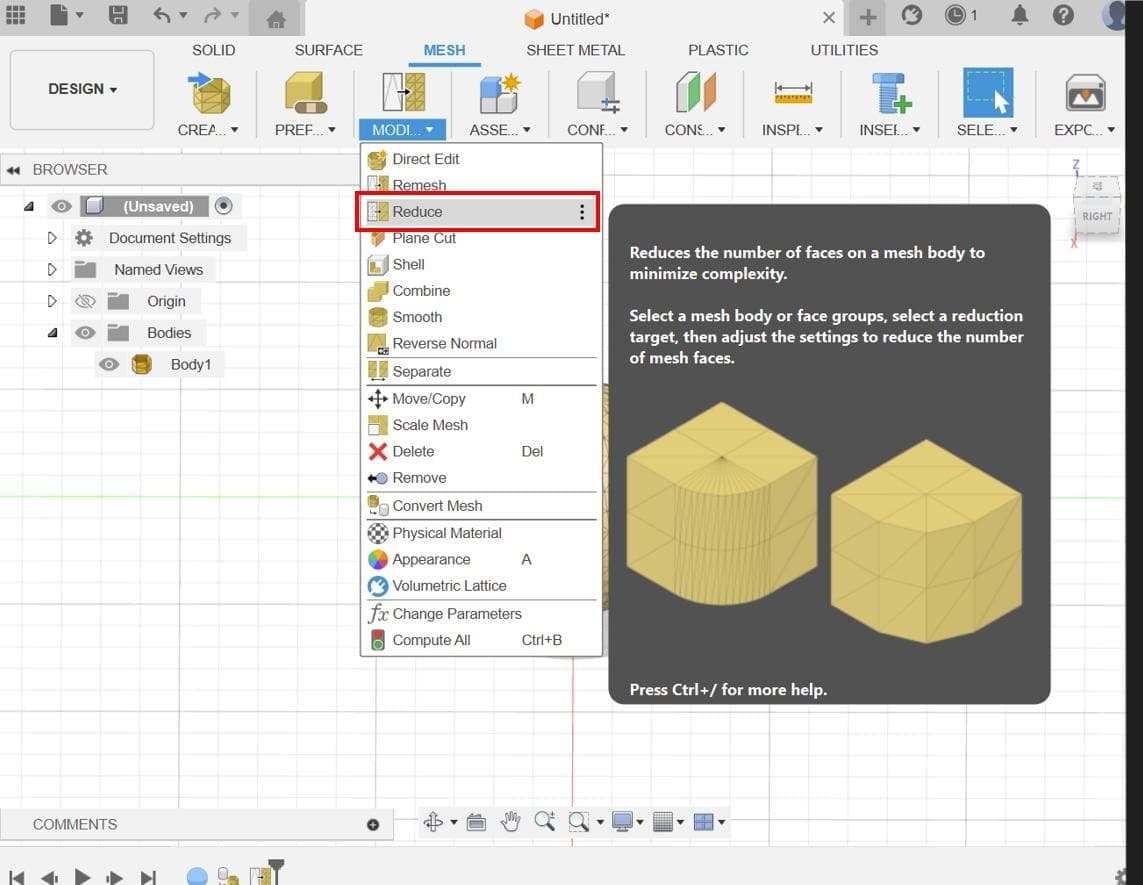
Reduce Mesh: Reduce the complexity of the mesh if needed. This step can help optimize performance and simplify the subsequent steps.
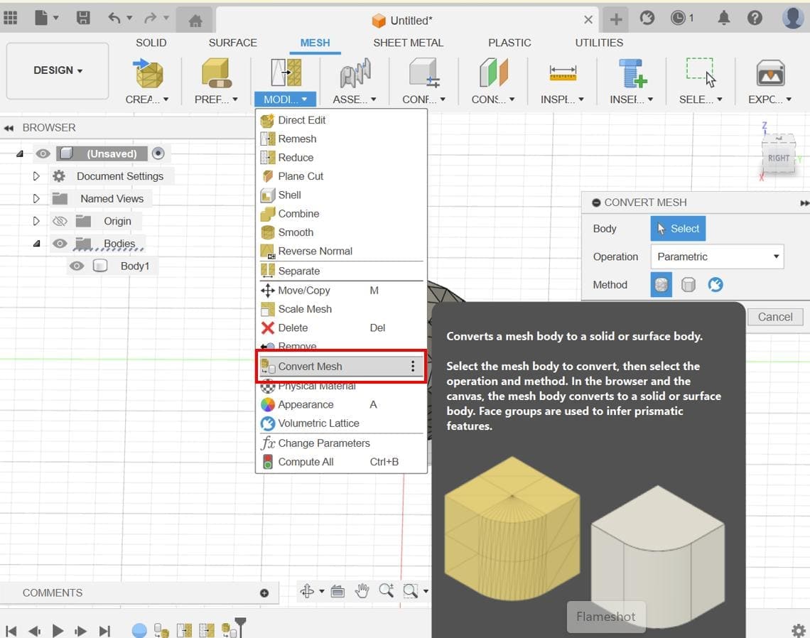
Convert Mesh: Convert the mesh into a form that can be used for further operations. Fusion 360 has tools for converting meshes into T-Spline or BRep bodies.
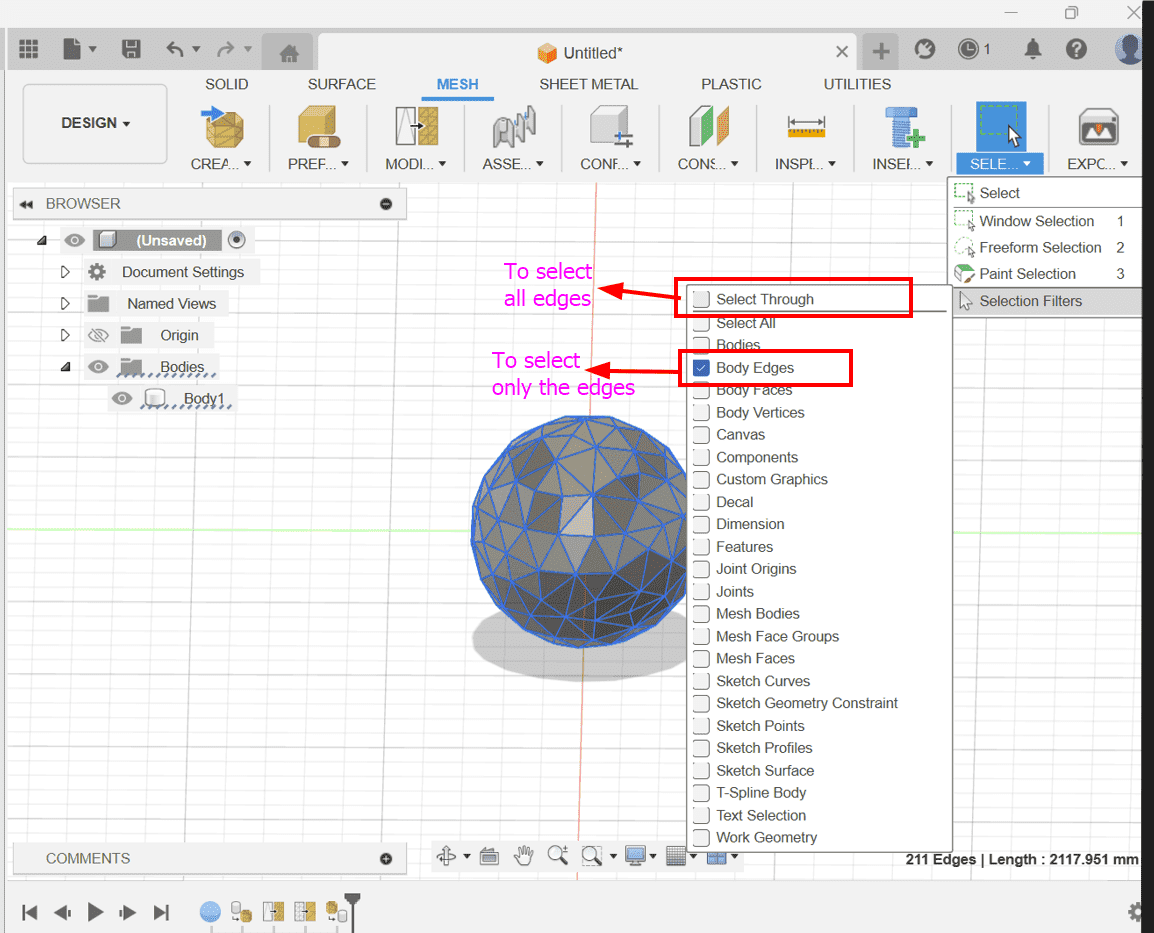
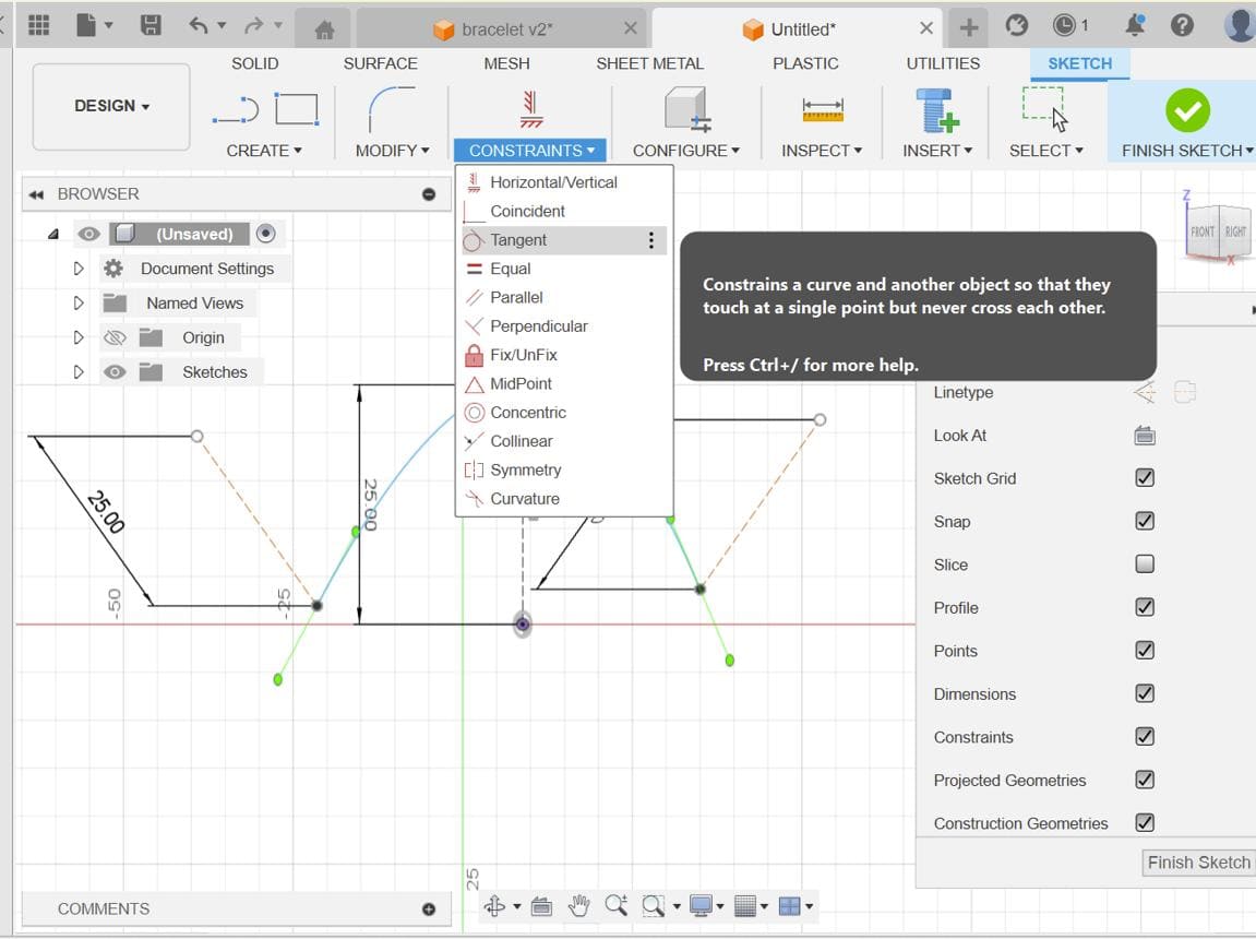
Select Priority and Enable Select Edge Only: Adjust the selection settings to prioritize edges and allow selection through objects. This will facilitate the selection of edges for the whole shape.
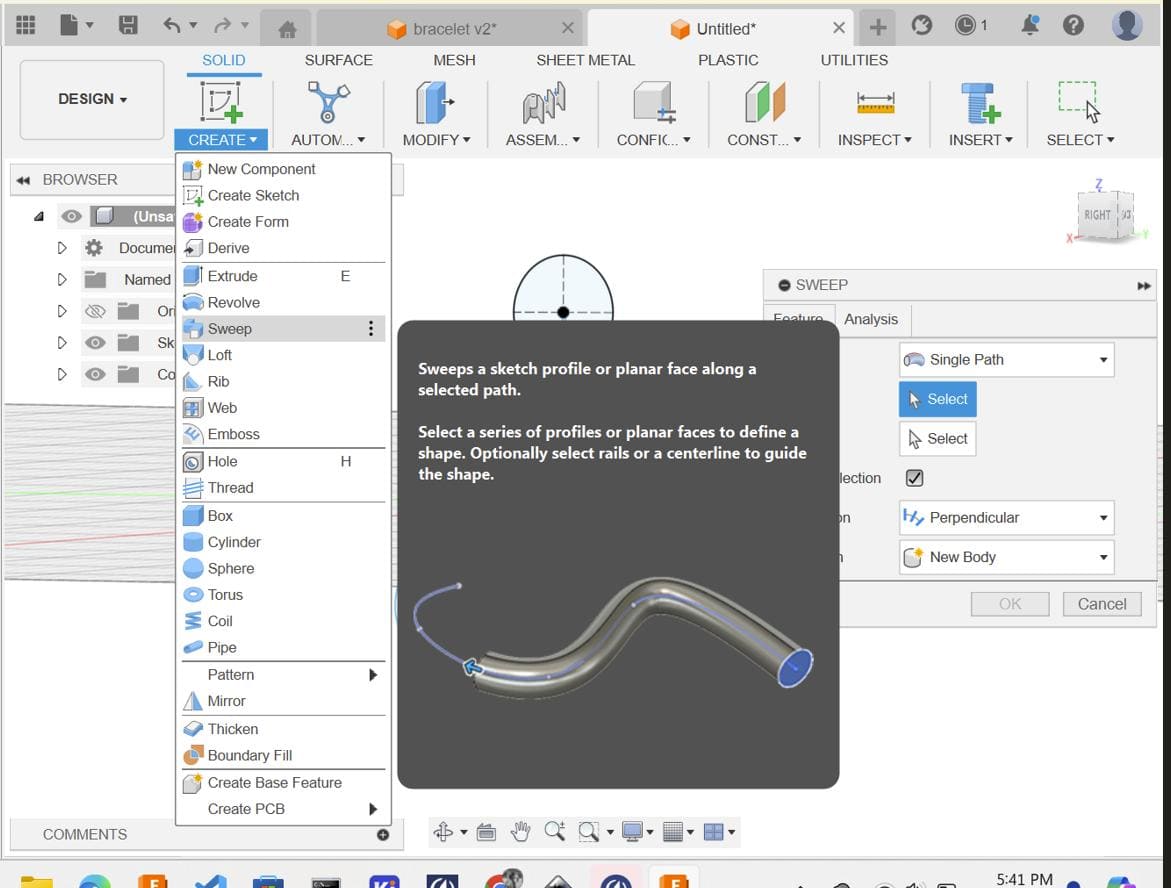
Add Pipe Form: Use the Pipe command to create tubular forms along the edges of the mesh. Adjust the parameters of the pipe as needed to achieve the desired thickness and appearance.
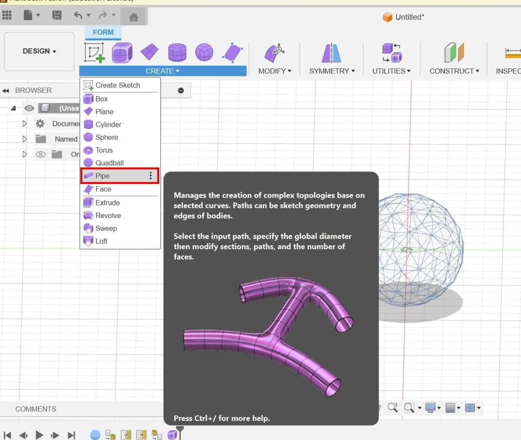
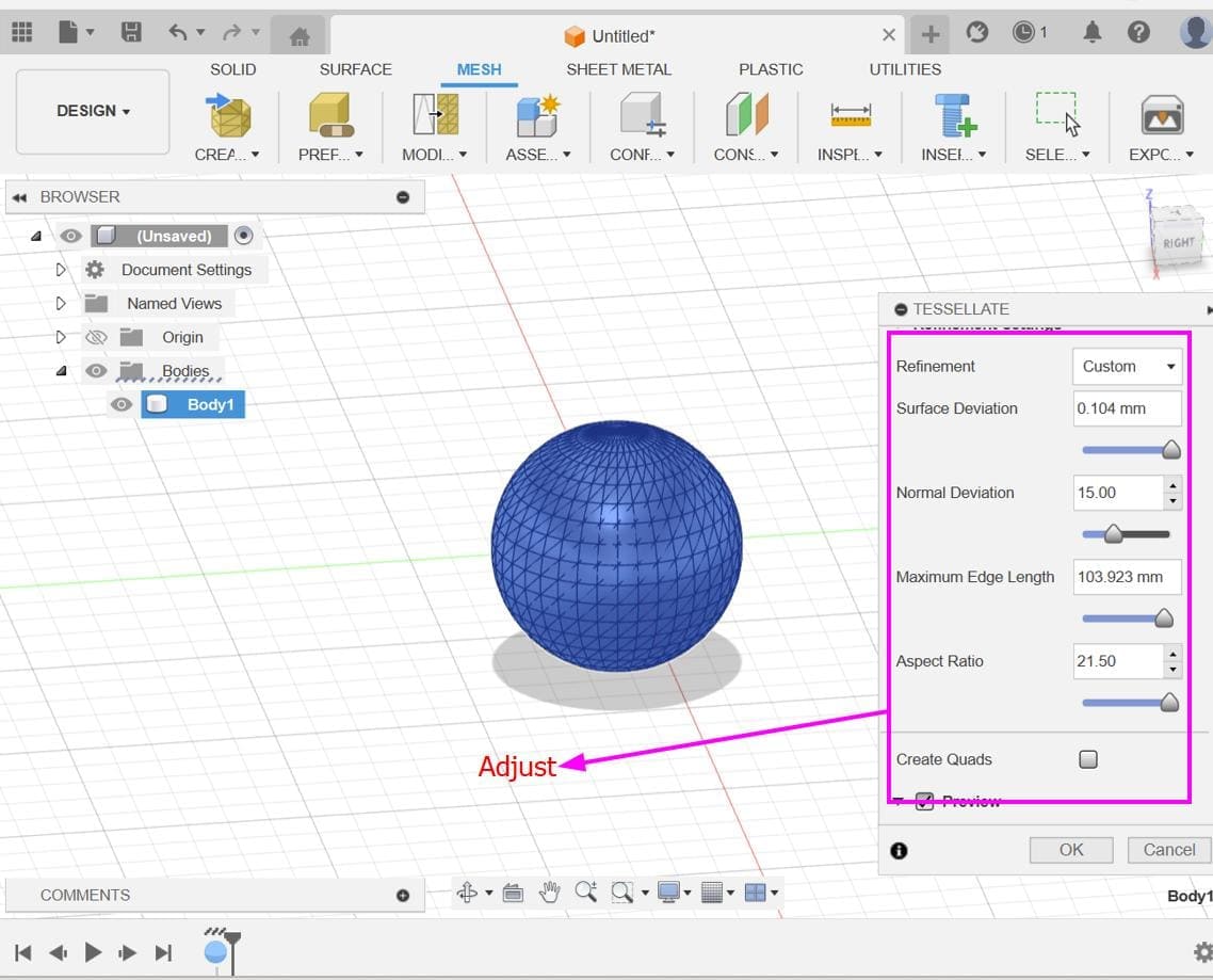
Adjust Diameter: Fine-tune the diameter of the pipes to achieve the desired aesthetic for the Voronoi-like pattern on the sphere's surface.
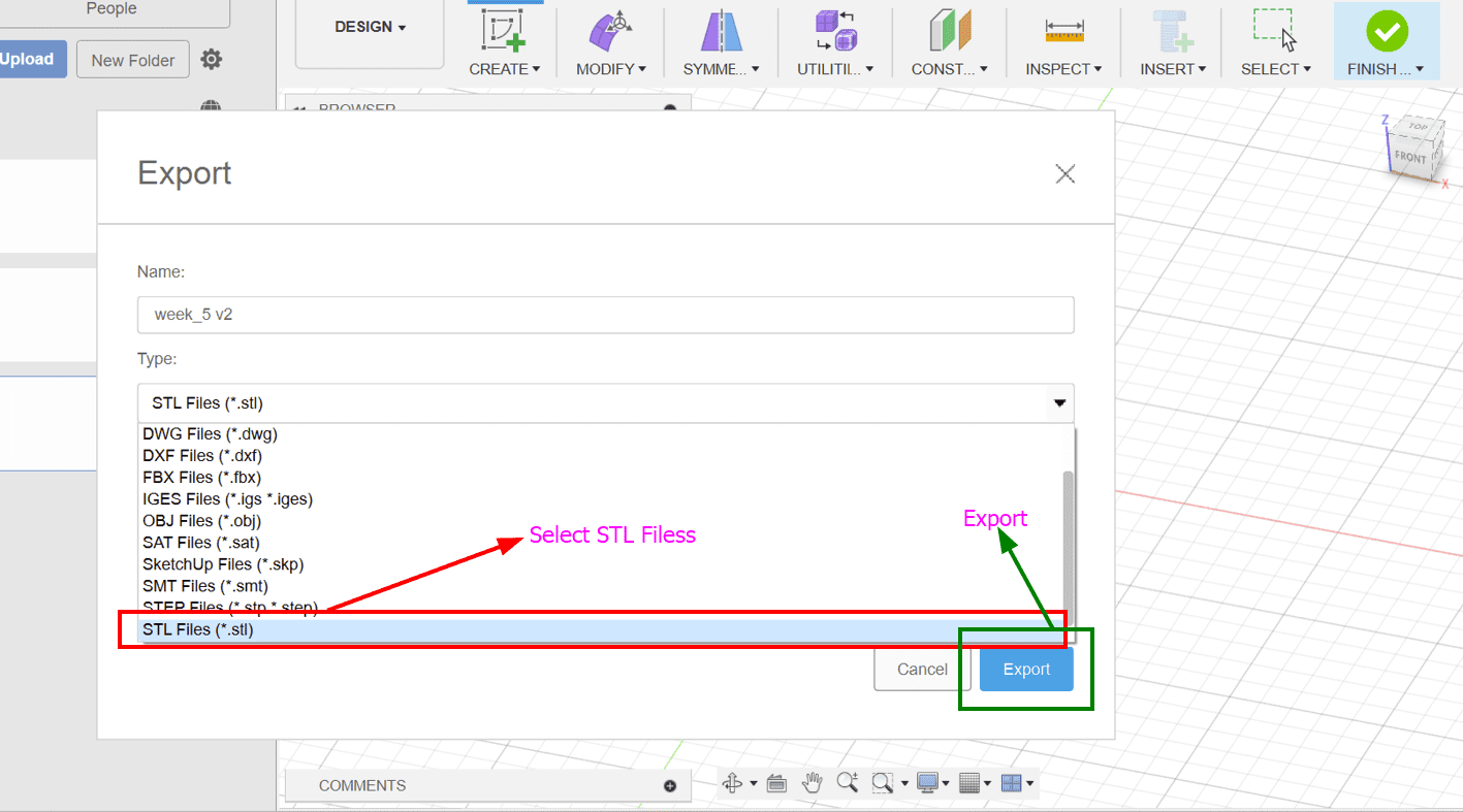
Choose "Export": From the "File" menu, choose "Export".
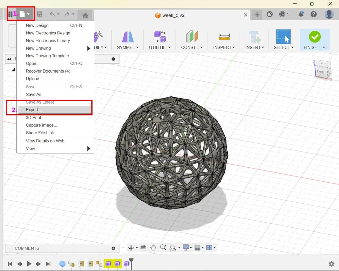
Select STL Format: In the export dialog that appears, select "STL" as the file format and export.
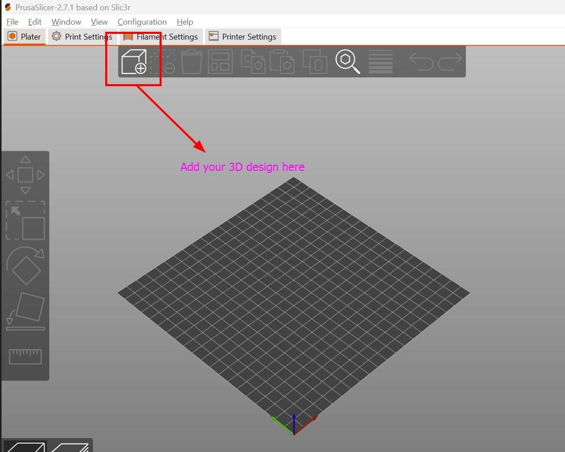
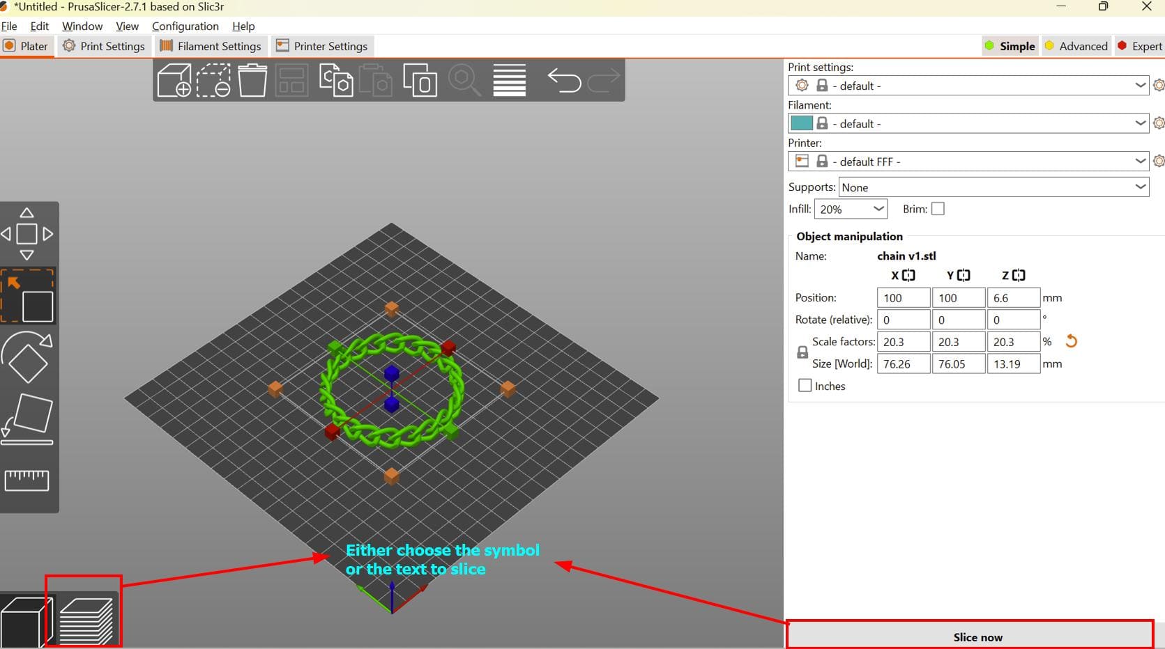
For the slicing part, I used Prusa Slicer. You can find the download link here !!
But then BOOM!! WARNING!!!

The print stability issue usually occurs when the model has overhangs, thin walls, or lacks proper supports.
In my case I think that it occured due to the lack of proper support.
I finally decided to make a new design because if I print this design, it will take me ages to remove the support.
So for the new design, I referred to this YouTube video
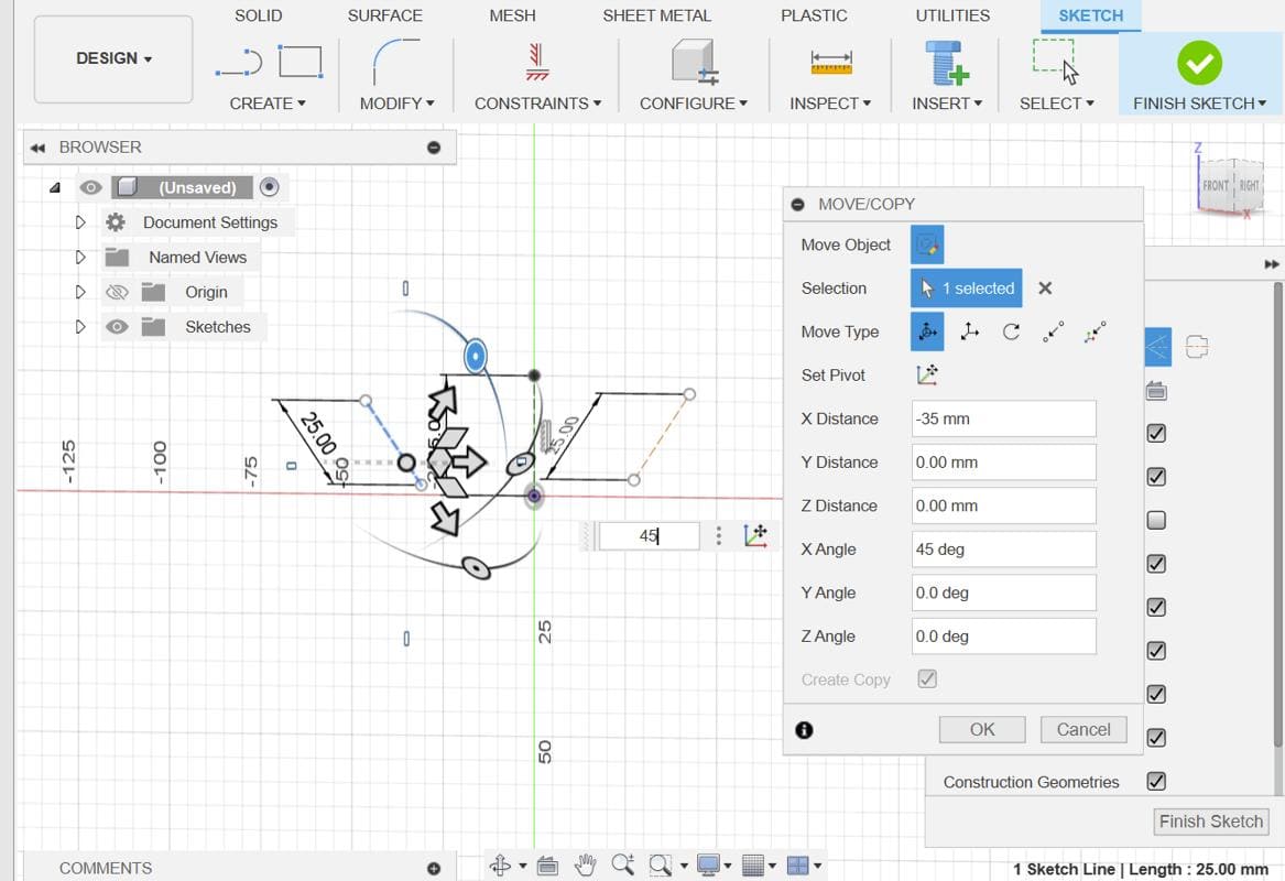
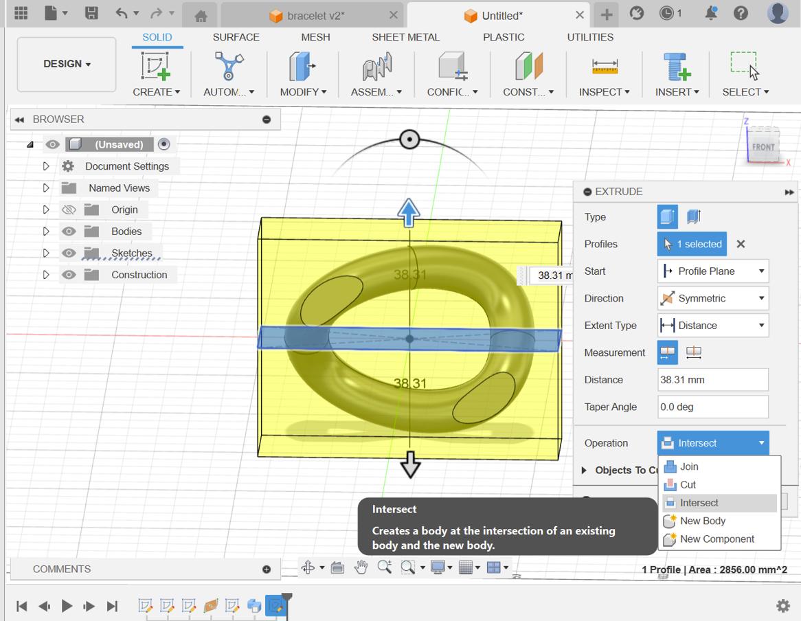
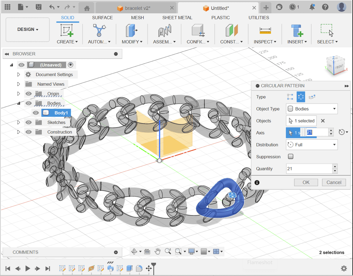
Move the entire body (likely the link structure) a distance of (51 * 21 / π / 2) from the origin. Make sure to specify the correct direction for the movement.
Select the link body and use the Circular Pattern tool to create multiple instances of the link around a circular path. Adjust the parameters of the pattern as needed.
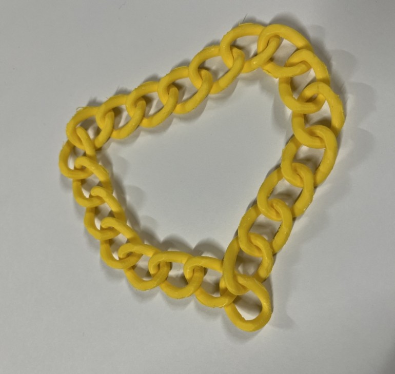
Here are the results!!:
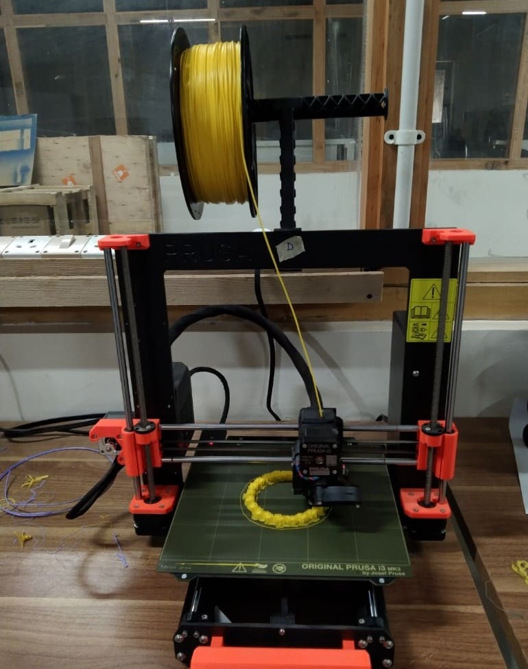
Here are the results!!! Thank you Thinley for helping me remove the support!!!

For 3D scanning, I used KIRI Engine which is a 3D scanning application that allows users to upload high-resolution images for generating lifelike 3D scans. It employs cutting-edge photogrammetry algorithms on cloud servers to produce professional-grade 3D outcomes for its users.
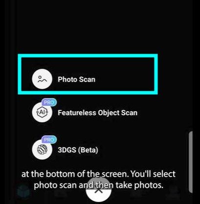
Select Options
After opening the app, select the photo scan option.
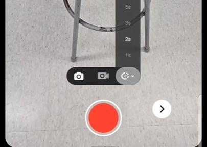
You can also record video of the object and generate the model.
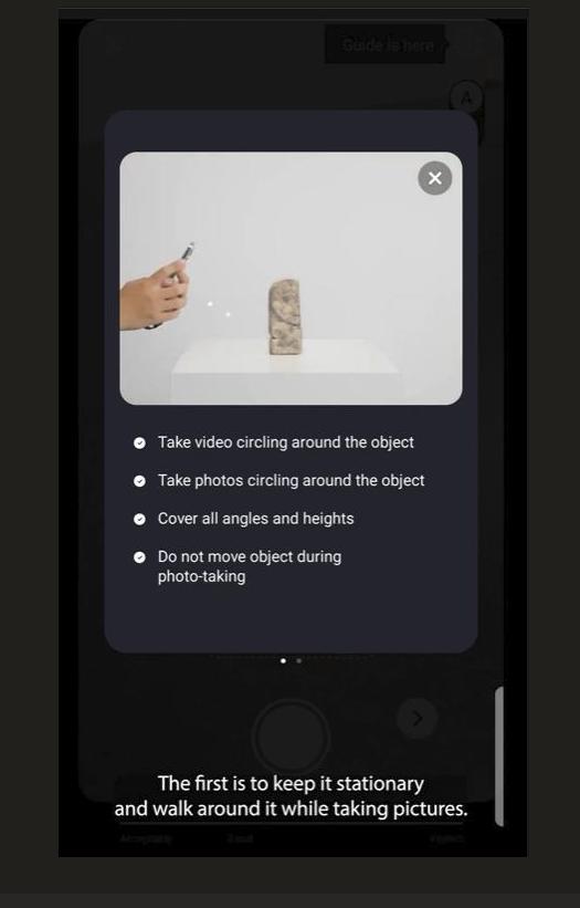
How to scan?
So, you can either move the camera around the object...
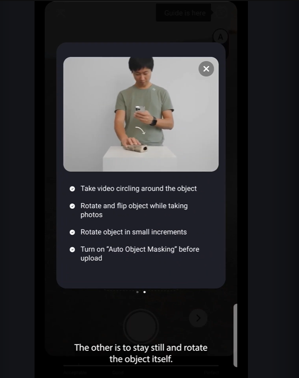
Or rotate the object while keeping your camera stationary.
Capture Images
To start, take several good quality images of the item or object that should be scanned. Take the images from different points of view. Besides, having more images gives the scan high quality in the 3D model.
Upload Images
For instance KIRI Engine, its 3D scanning app can be used to send the images to the cloud servers. These servers shall allow processing of the images with such photogrammetry algorithms.
Processing
The software determines the image points, it derives the same coordinates (intersection points) from the image and constructs the 3D model based on them.
Refinement
As the reconstruction goes in automatic mode, we can work on the refined 3D model by modifying parameters or performing manual tuning on certain areas, which help us to achieve more exact measurements.
Final Output
After you are through, the output the software will generate would include a 3D scan which can be used in different scenarios such as 3D printing, virtual reality, and animation.
The following model was 3D printed by some students of our school for their Biology Project.
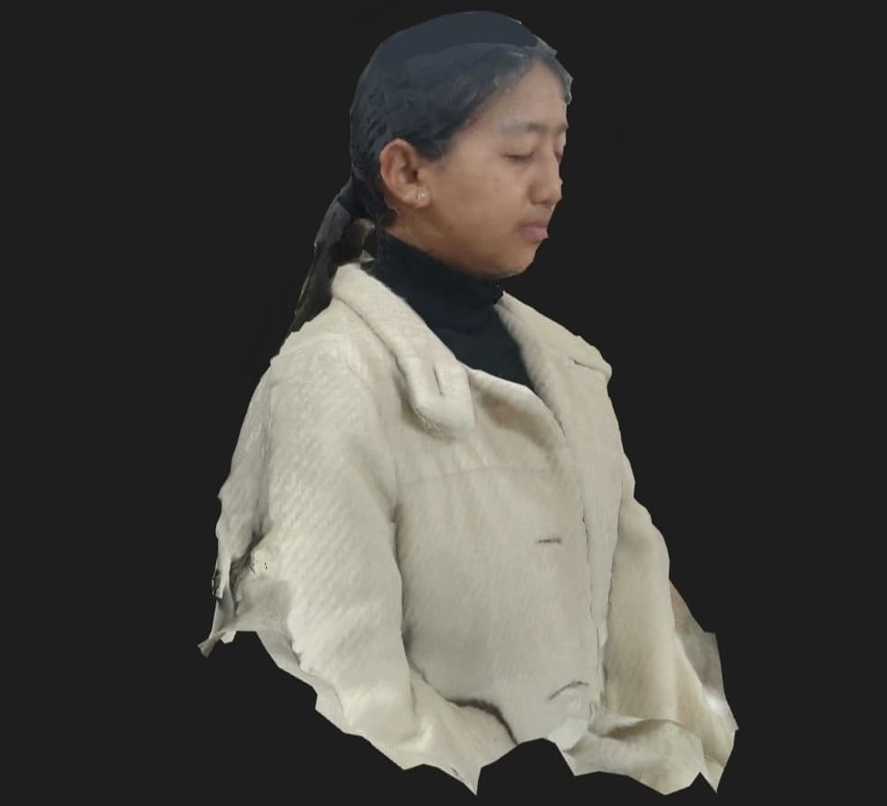
I also tried scanning one of my friends and it wasn't that bad:)