Group assignment:
Individual assignments
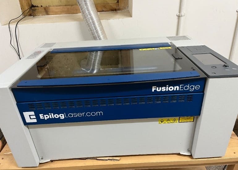
A laser cutter is a tool used in prototyping and manufacturing to cut and etch flat materials. It operates by directing a focused laser beam to pierce and cut through materials according to specified patterns and geometries.
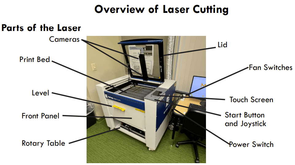
This is the C02 laser cutter that we have in our lab
These are all the functionalities of the touch screen control panel
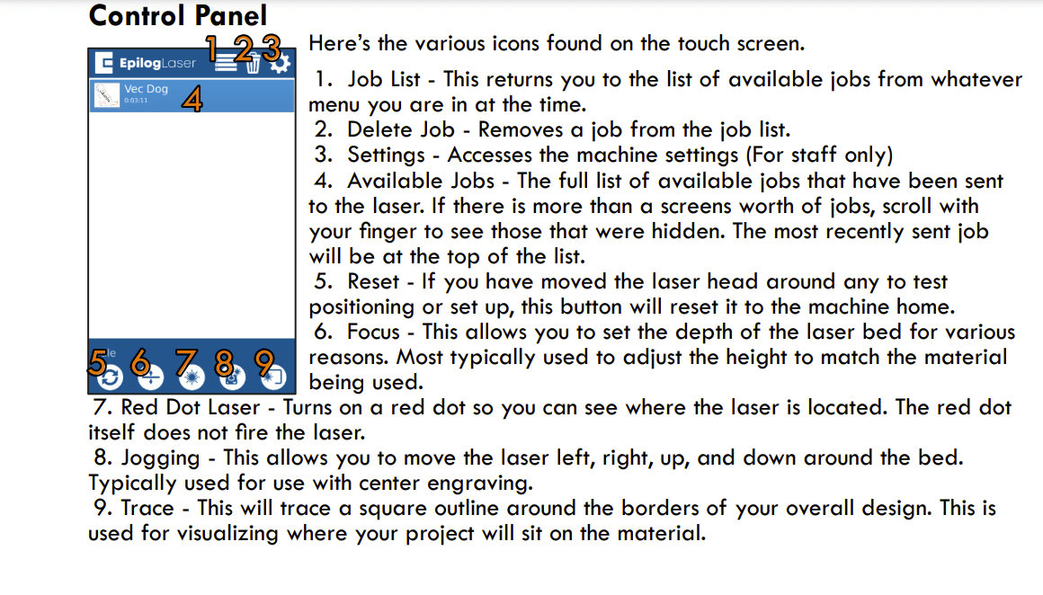
I got the above 2 images from an online Epilog Fusion Edge Laser Cutter handbook .
Laser systems can produce high temperatures, especially in vector cutting, and can result in burning when used with materials like acrylic. Always remain with the laser while in operation, make sure the area is clear of combustible materials, and have a fire extinguisher nearby.
The Epilog Model 16000 & 17000 laser systems have safety features like safety enclosures, interlocks that de-energize the laser when doors are open, visible emission indicators for the Laser Diode Pointer, and more. Do not remove panels and NEVER defeat the door interlocks.
These laser systems are Class 2 laser products and conform with safety standards. Do not gaze directly into the laser beam. NEVER operate the engraver without protective covers on at all times, or look directly into the Laser Diode Pointer.
The AC input power is potentially lethal. Do not remove access panels while the machine is powered, and do not make or break electrical connections while power is applied. Do...
Do Not...
Key learning:
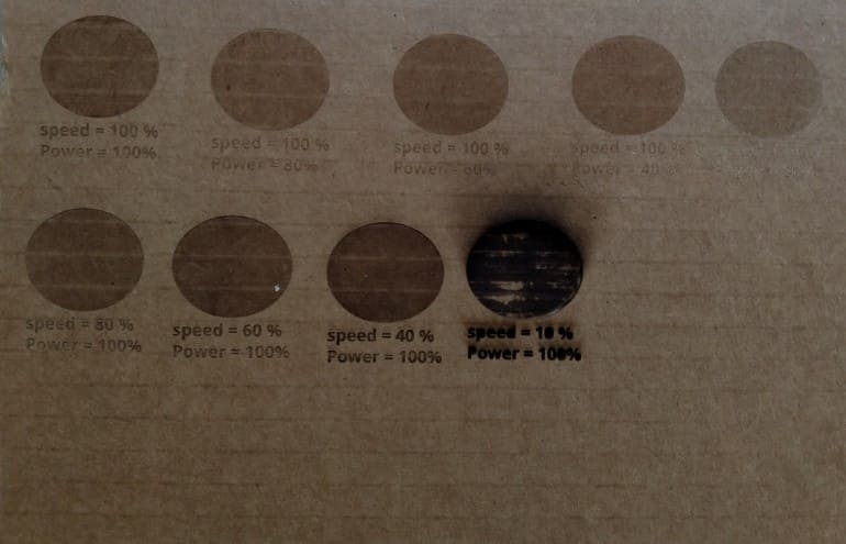
To get the best results with laser cutting, you need to balance how powerful the laser is and how fast it moves. For thicker or tougher materials, you might need more power. But if you go too slow, the material might burn. So, adjusting the speed helps control how much heat the material gets. It's like finding the right recipe for each material and design by trying different settings until you get the perfect cut.
Kerf is defined as the width of a cut or width of a material that is removed by a cutting process.
For this week, one of our assignments was to characerize the laser cutter's kerf. Now, measuring kerf size accurately is essential to ensuring your laser machine's performance for your desired outcome.
material_thickness - kerf = slot_width
These are the steps that we followed to measure the laser kerf:
Design a piece with known dimensions. Keep it fairly small.
Cut it with the laser cutter.
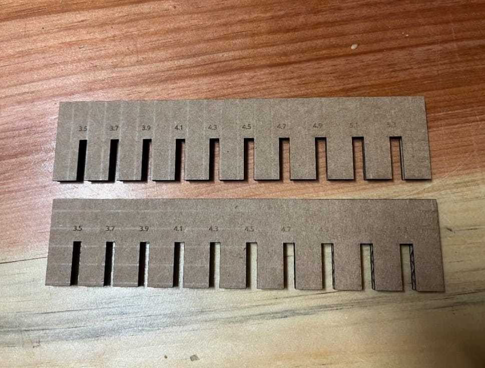
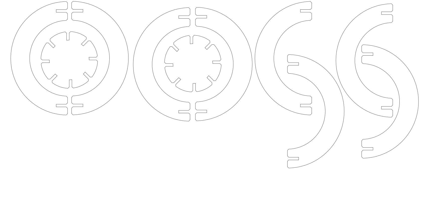
In our case we designed a simple shape with slots which differed in size by 0.2 mm
We used a digital caliper to measure the slots accurately
Compare this to the measurement that you had in your file and calculate the difference between them.
Divide the result from this calculation by two. (Since you have two lines that were cut, left and right or top and bottom).
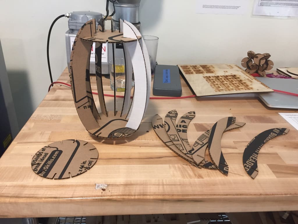
Here is the complete Group Assignment
The third key concept is parametric design. This is an ordered way of working where specific details are given only in relation to one or a few base or control measurements. Then you are able to change the dimensions of the geometry by altering only those control measurements and the other, dependent, dimensions adjust themselves.
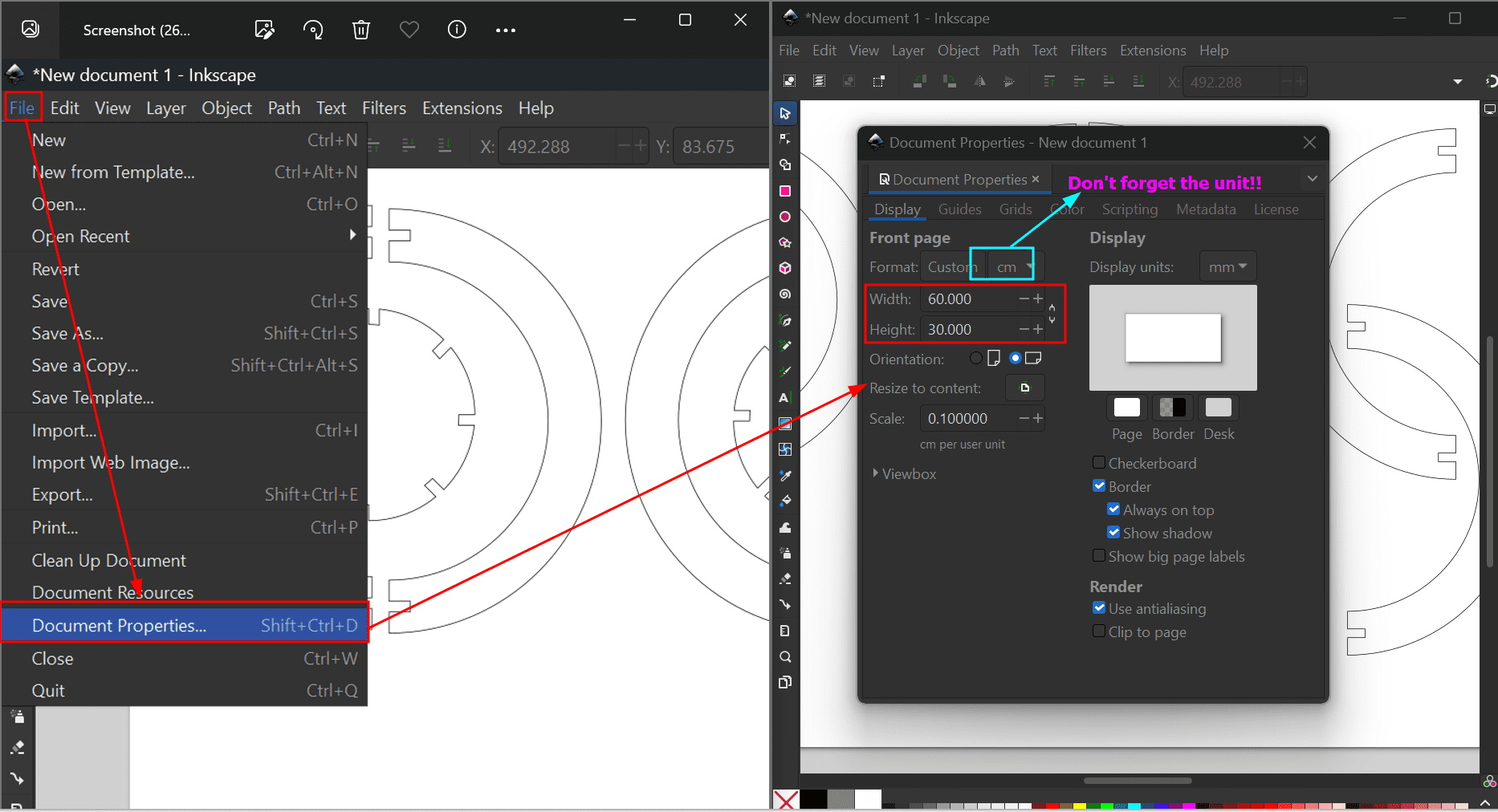
For the parametric construction kit, I decided to make a pressfit design in fusion and here are all the steps:
For the pressfit parametric design, I explored some ideas on google and found some really nice and beautiful designs. But I found them quite complex plus there weren't any TUTORIALS for the design!! So, I decided to make this as I found it simple and cool.
For this, I created my own design in Fusion 360
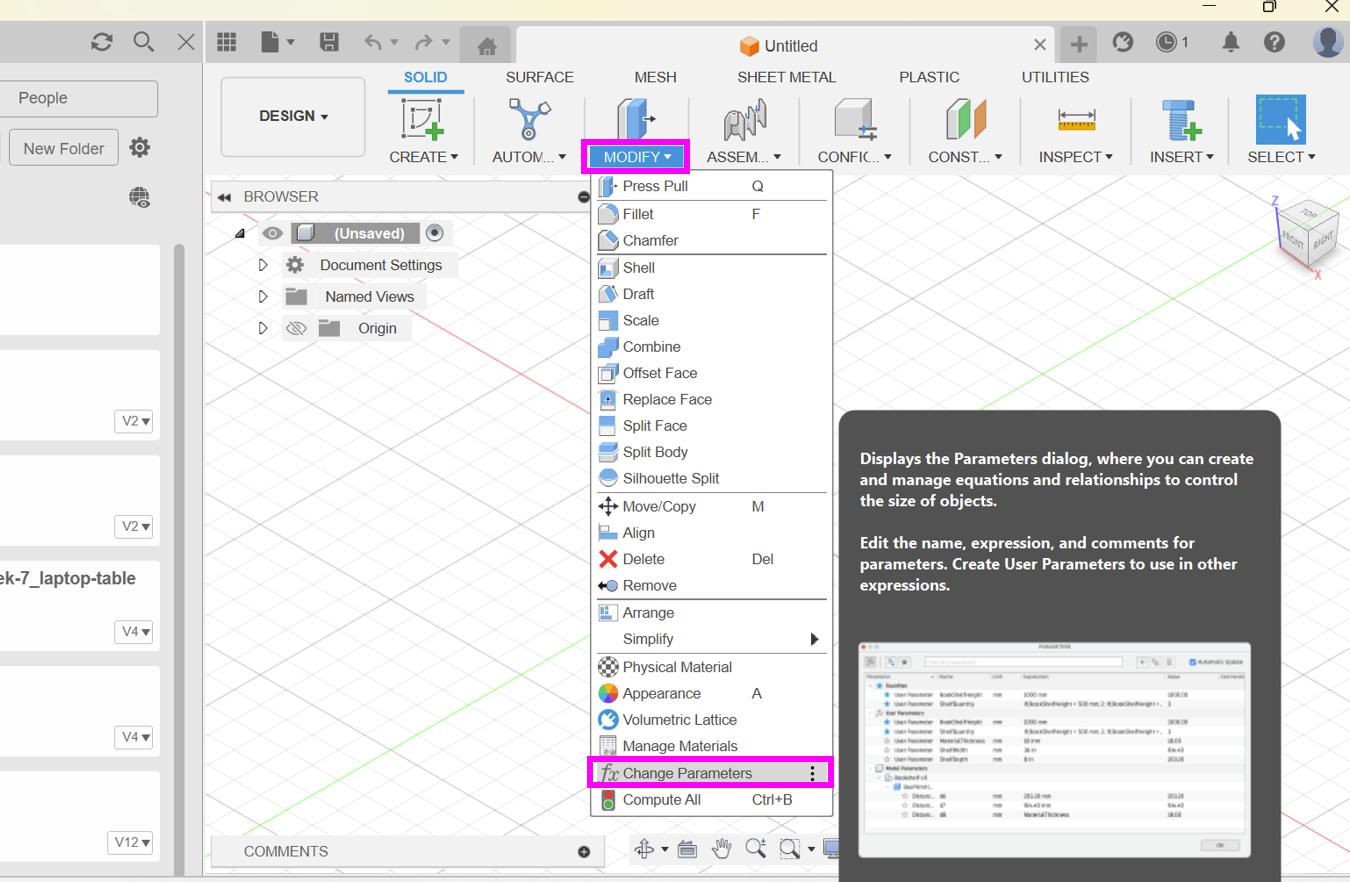
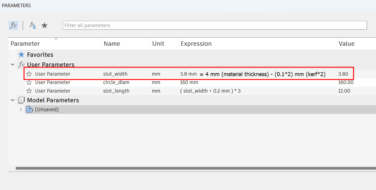
To navigate to the parameter box, first go to modify and then to change parameters
We got our kerf as 0.1 mm, so we multiplied by 2 as we are calculating for two sides and subtracted the value from the
material thickness which gave us the slot_width
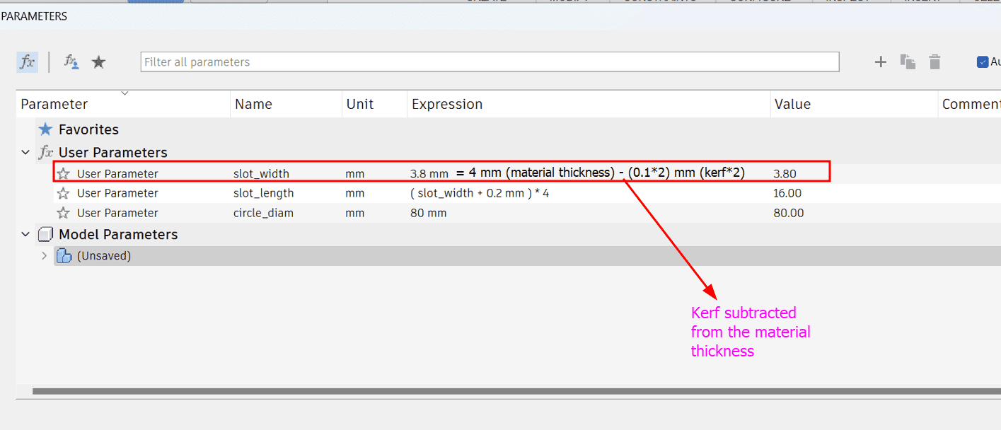
circle_diam - slot_length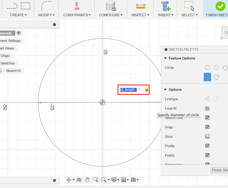
circle_diamThe space between the two circles gave me the slot_length
slot_width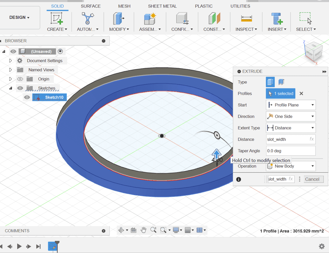
slot_width
as its side length.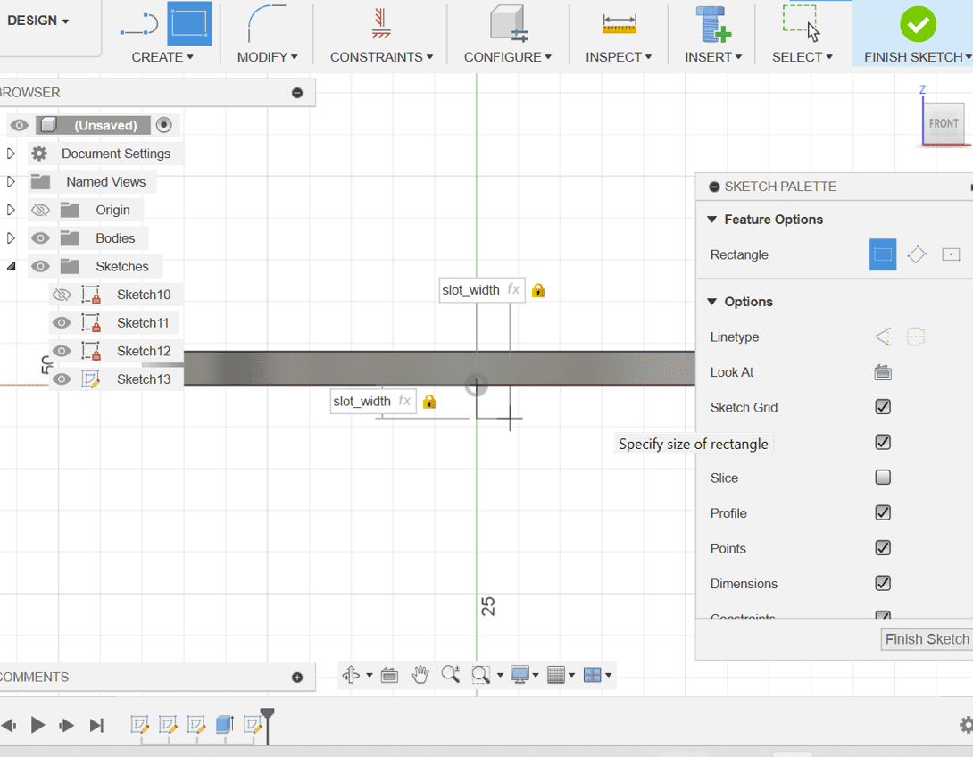
Now we got a slot with the correct slot lenght and the correct slot width.
Here are the results:
slot_width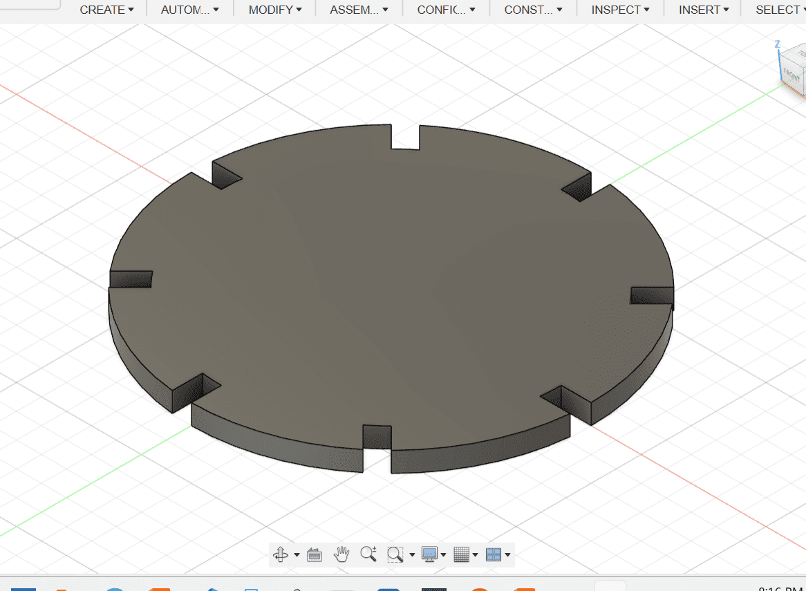
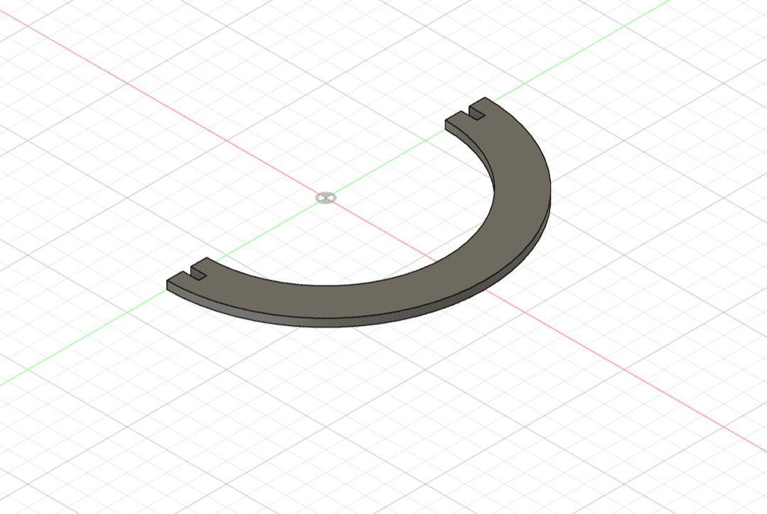
2. Create a sketch of a circle and extrude it by setting the value as slot_width
3. Then split the circle in two and create another sketch on the semi-circle for the slot.
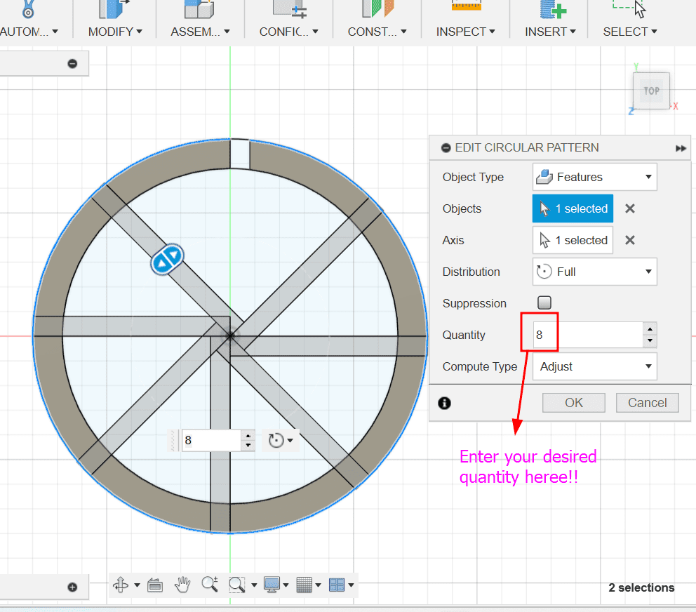
circle_diam/4slot_width and slot_length respectively.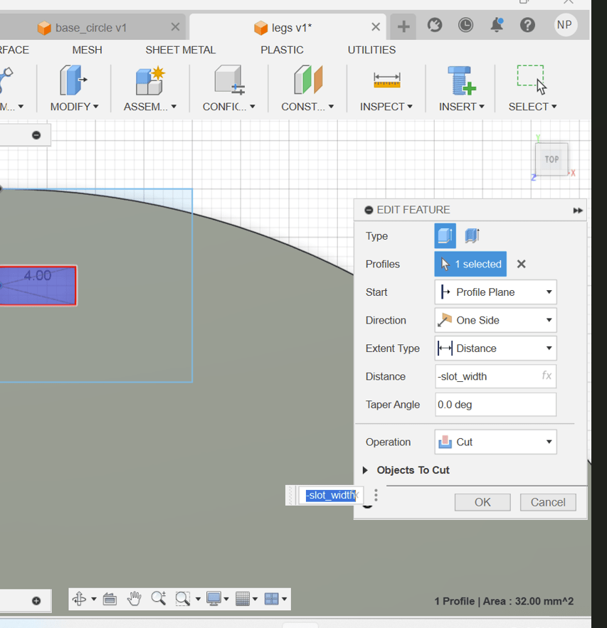
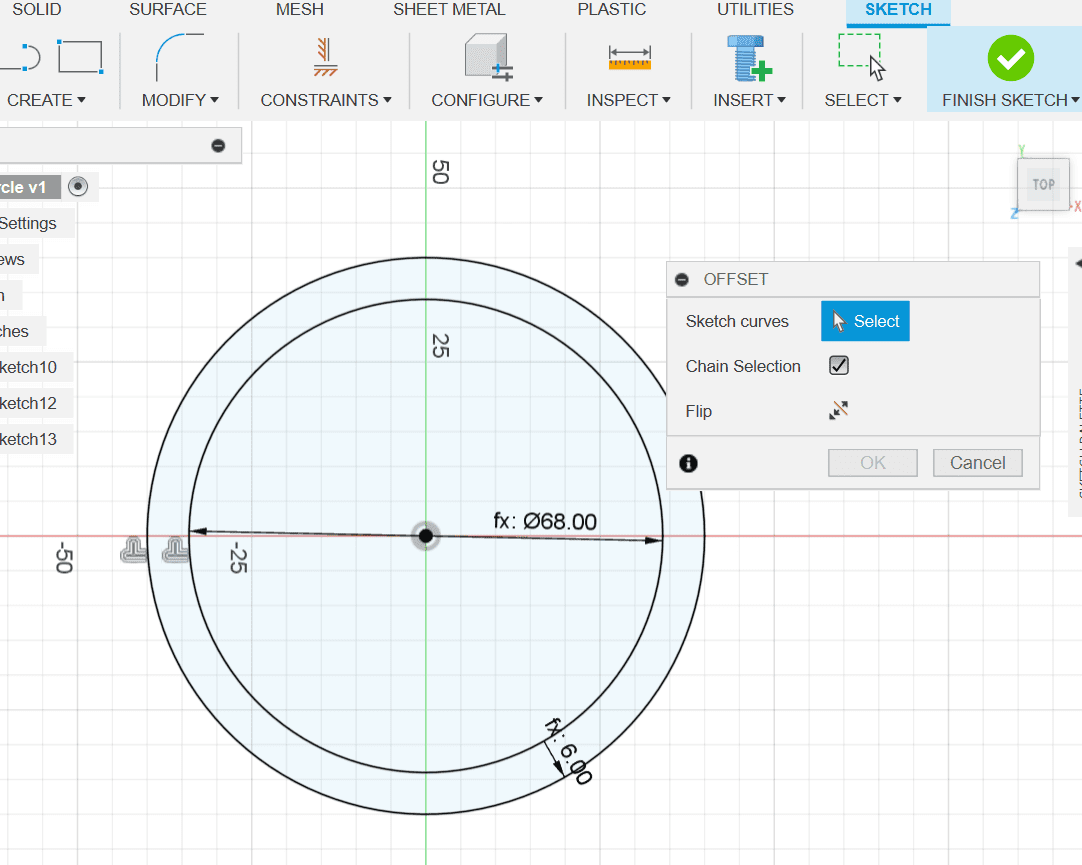
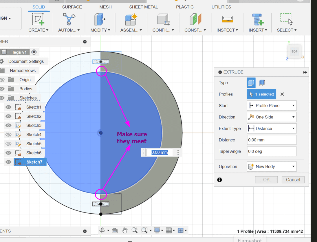
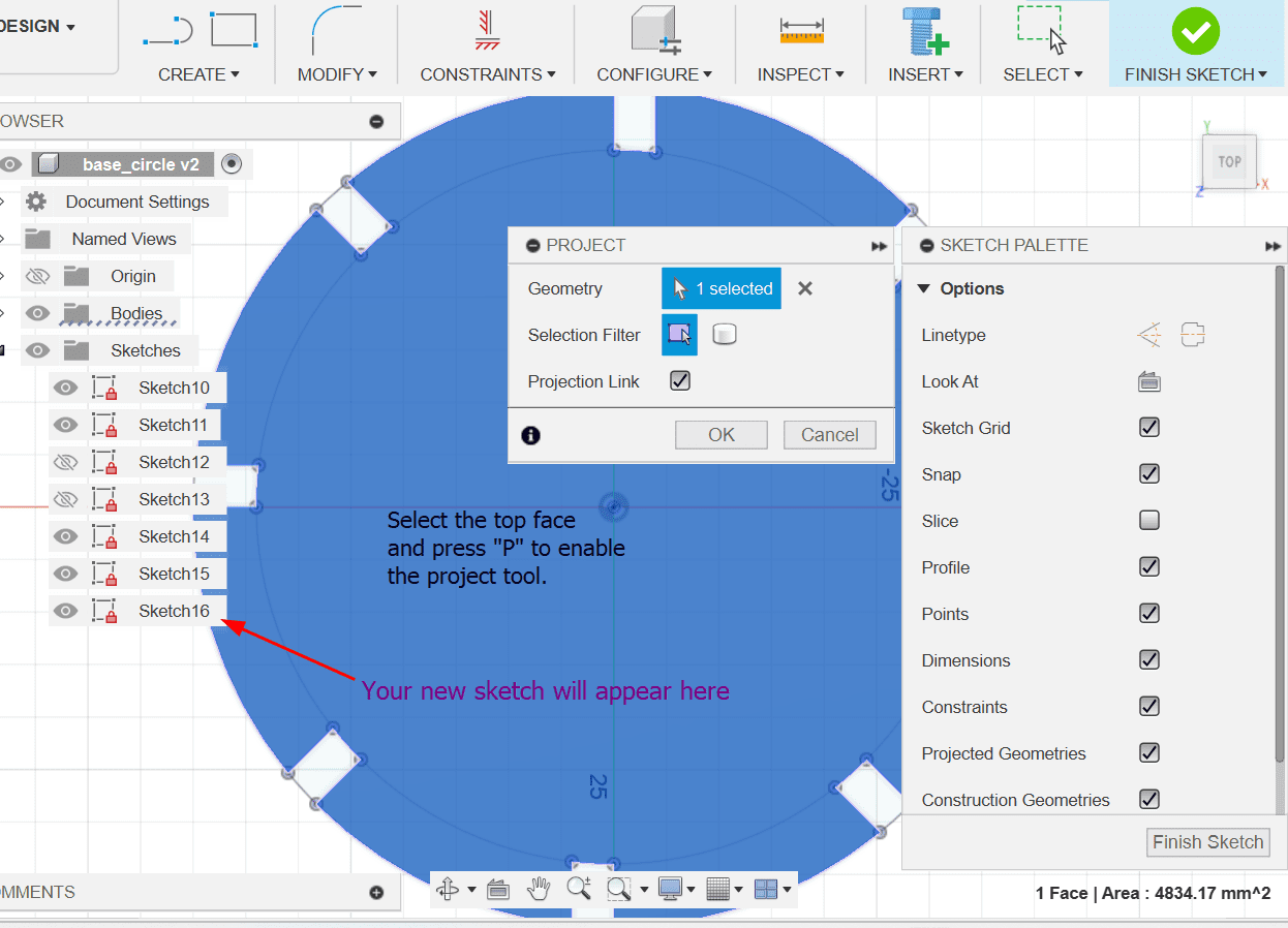
4. Then go back to sketch mode and make a circle which just meets the corners of the squares.
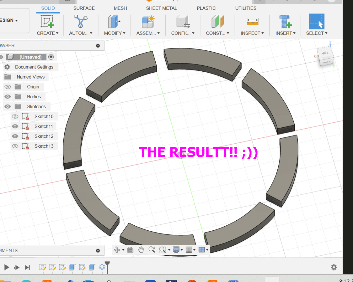
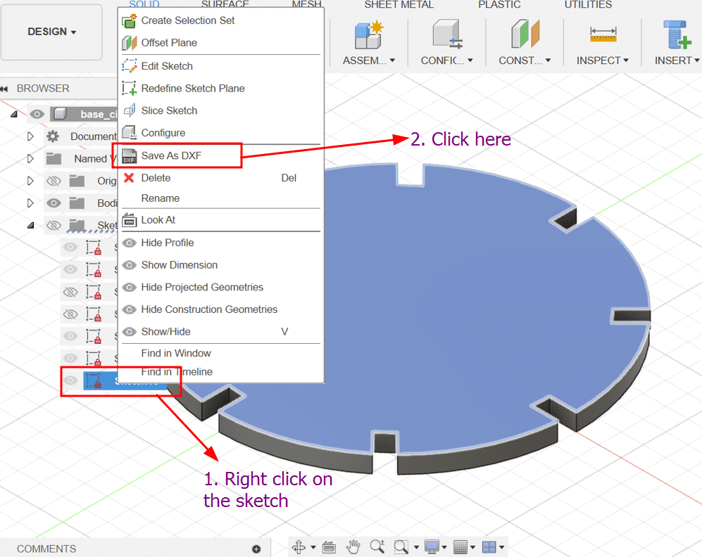
Here is the result!!!
After I was done designing the shapes, I chamfered the edges.
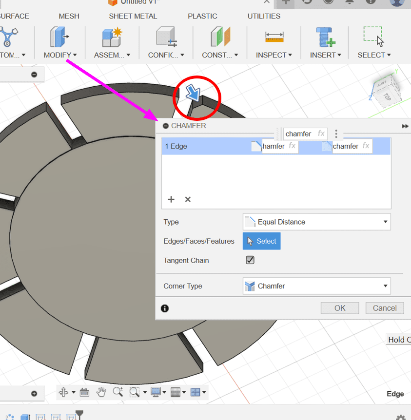
ALL DONE!!!
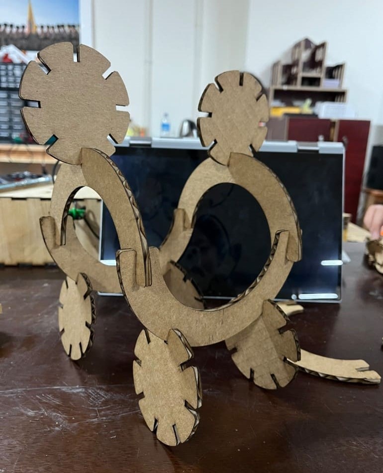
Here's the design I wanted to make!!!
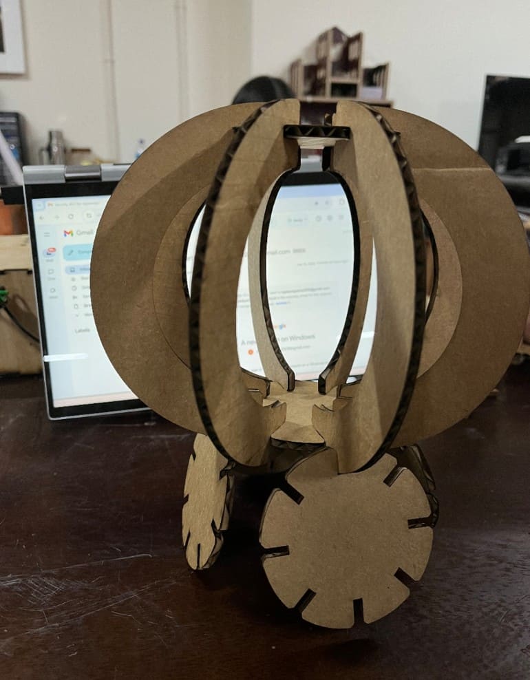
And guess what?? CINDERELLA'S CARRIAGE!!
This is the vinyl cutter that we have in our lab:
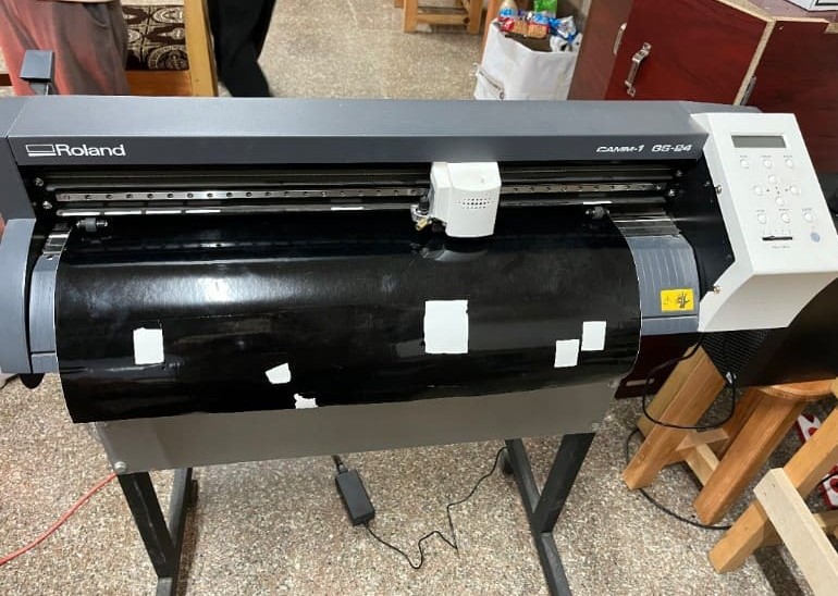
Model: GS-24
Input: 24 V , 0.9 A
Maximum cutting area width: 22.9 in (584 mm), Length: 984.25 in (25000 mm)
Maximum cutting speed 19.69 in/s (500 mm/s) (all directions)
A vinyl cutter serves as an introductory tool for crafting signs. It operates by directly cutting computer-generated vector designs, encompassing patterns and text, onto a roll of vinyl. This vinyl material is loaded into the cutter and fed via either a USB or serial cable connection. Primarily utilized in sign-making, vinyl cutters are instrumental in producing banners, advertisements, and various signage.
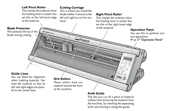
The following image shows a labelled vinyl cutter with the function of each component. This is the same model as we have in our lab.
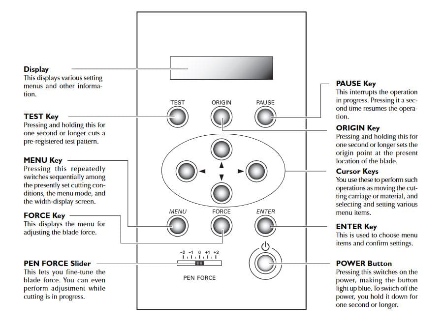
Here are the functions of the operation panel:
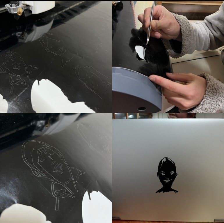
For the vinyl cutting, I decided to print a sticker of me and my friends that Sir Rico drew for us!!!
So firstly I had to use 'trace bitmap' tool for the process which I have done in detail in the previous week but here is a very brief process:
That's it! You've successfully traced a bitmap in Inkscape!!
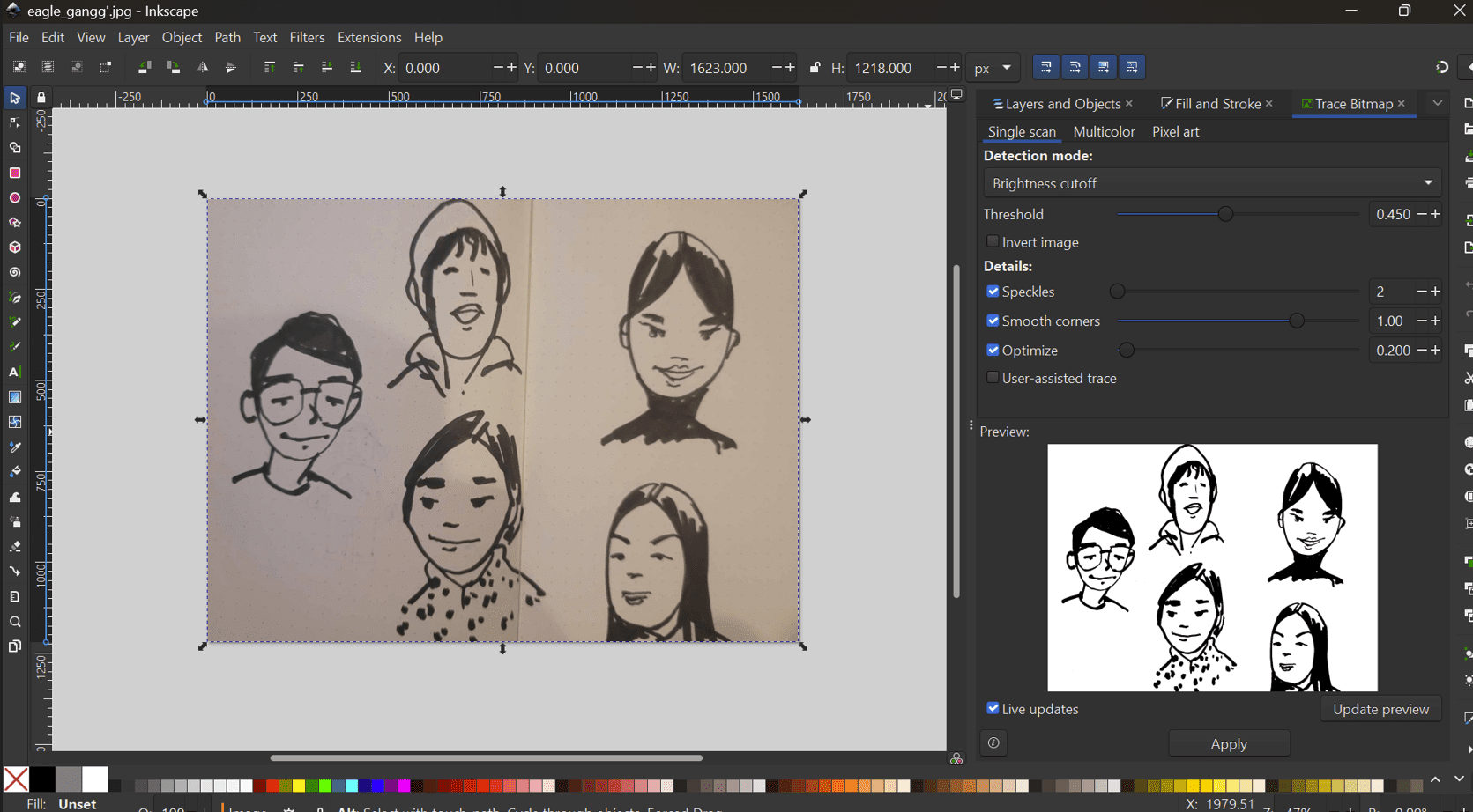
This is the eagle gang, by the way. We got this name after our instructor, Sir Anith's former friend group name.
Import Design: Import your design into the cutting software. Ensure that the design is correctly scaled and positioned within the cutting area.
Configure Cutting Settings: Set the cutting parameters such as blade depth, speed, and pressure based on the type and thickness of the vinyl material you're using.
For this cut, I used the pre-filled value using the material selector : - Force : 10 - Speed : 5
Perform Test Cut: Before cutting your entire design, it's a good idea to perform a test cut on a small piece of vinyl to ensure that the settings are correct.
Send Design to Cutter: Once you're satisfied with the test cut, send the design to the vinyl cutter for cutting. Make sure the cutter is set to "cut" mode.
The above parameters (force and speed) worked for my test cut so I am proceeding with my main design!!
Monitor Cutting Process: Keep an eye on the cutting process to ensure that the vinyl is being cut correctly and there are no issues.
Your sticker is now applied and ready for use!
This is the the final result of my cut! And it turned out pretty well!!
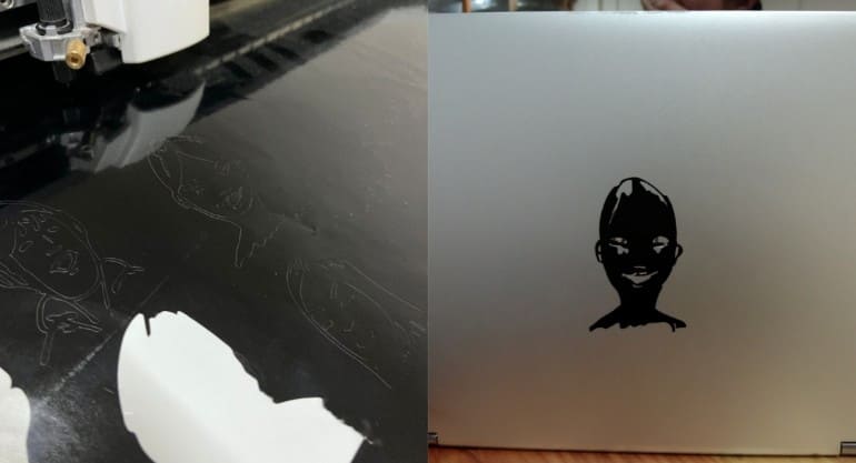
I had a really hard time weeding as the graphics were pretty intricate but I had fun!!
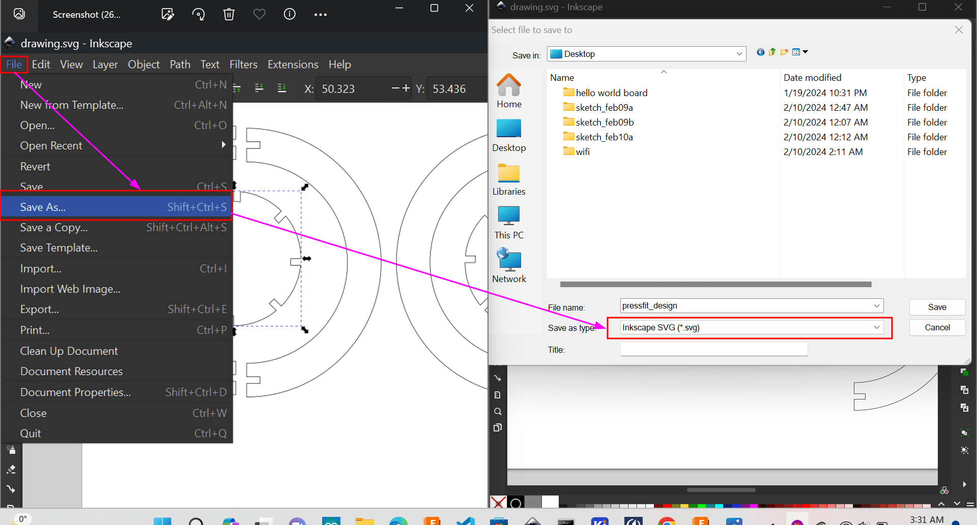
Design Files
Here is the link for our group assignment Group Assignment: