Group assignment:
Probe an input device(s)'s analog levels and digital signals
Document your work on the group work page and reflect on your individual page what you learned
Individual assignments
Learning outcomes:
Requirements for the assignment:
Linked to the group assignment page.
Documented what you learned from interfacing an input device(s) to your microcontroller and optionally, how the physical property relates to the measured results.
Documented your design and fabrication process or linked to the board you made in a previous assignment.
Explained the programming process(es) you used.
Explained any problems you encountered and how you fixed them.
Included original design files and source code.
Included a ‘hero shot’ of your board.
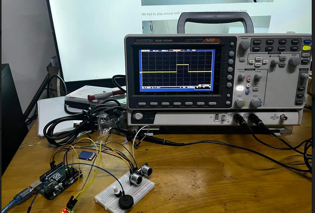
For this week, we got instructions to use tools like multimeters and oscilloscopes to check the signals from a sensor for our group task this week. Our group decided to test an ultrasonic sensor and used an oscilloscope to see its signal.
An oscilloscope is a device that shows electrical signals as waveforms on a screen. It has parts like probes, signal systems, and vertical/horizontal controls.
We started by writing Arduino code in the Arduino IDE for the ultrasonic sensor. The code sends out a signal, measures the time it takes to bounce back, and calculates distances in inches and centimeters. Then, it sends this data to the serial monitor every 100 milliseconds.
For the ultrasonic sensor, we connected its Echo pin to digital pin 6, Trigger pin to digital pin 7, Ground to Ground, and Vcc to Vcc. We hooked up the oscilloscope probes to Ground and Echo pins to view the signal.
The code for the ultrasonic sensor works fine, but when we tried a sound sensor (which converts sound waves into electrical signals), it didn't detect sound waves well. We used the analog serial example code from Arduino, changing the pins as needed.
The oscilloscope and serial monitor showed how the ultrasonic sensor and sound sensor signals looked. The ultrasonic sensor worked better than the sound sensor in our tests.
Here is the complete group assignment.
Heroshot!!
For this week as I don't have a moisture sensor which I will need for my final project, I want to try out an ultrasonic sensor with my ATtiny1614 board.
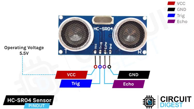
Ultrasonic sensors work by sending out a sound wave at a frequency above the range of human hearing. The transducer of the sensor acts as a microphone to receive and send the ultrasonic sound. Our ultrasonic sensors, like many others, use a single transducer to send a pulse and to receive the echo. The sensor determines the distance to a target by measuring time lapses between the sending and receiving of the ultrasonic pulse.
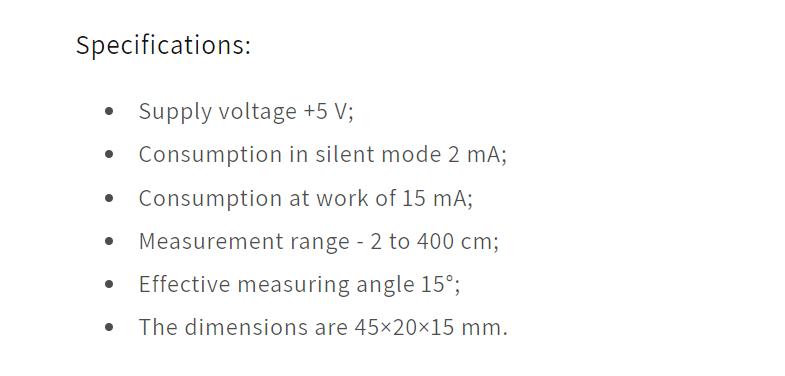
Here are the specifications for Ultrasonic Sensors that I came across while studying about ultrasonic sensor from this site.
For the ultrasonic sensor, I had to redesign my board from Week 9 (output devices week).
First I made the schematic design of my board.
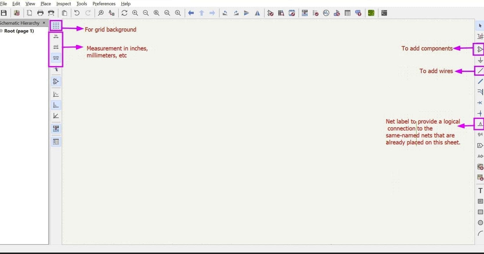
Here is a basic user interface of the schematic KiCad.
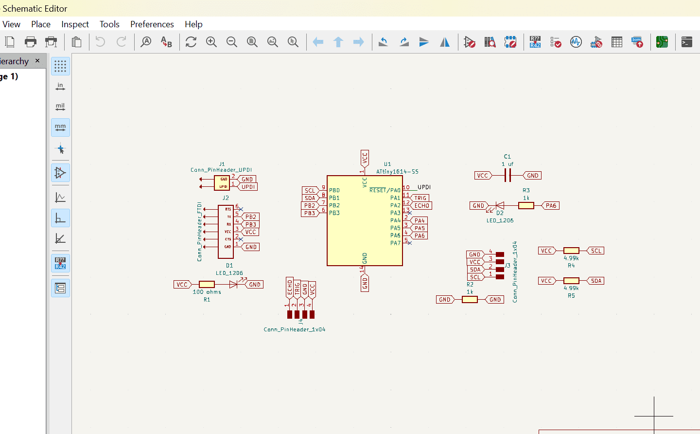
This is the final look of my schematic design after considering the pinouts of the ultrasonic sensor.
After running the ERC and having no errors, I updated the schematic to PCB and designed the board.
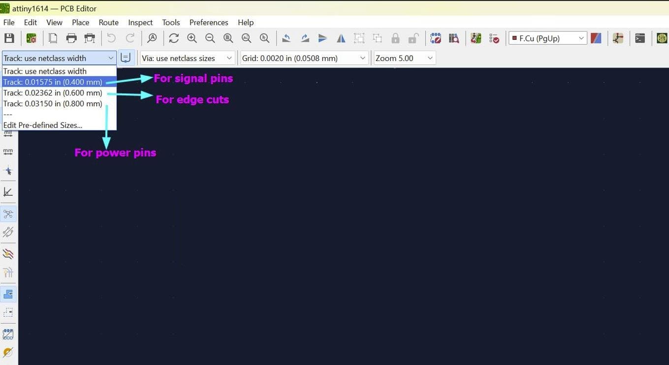
Like the proevious weeks, I used 0.8 mm width for my power routes, 0.4 mm width for my signal routes and 0.6 mm for my edge cuts.
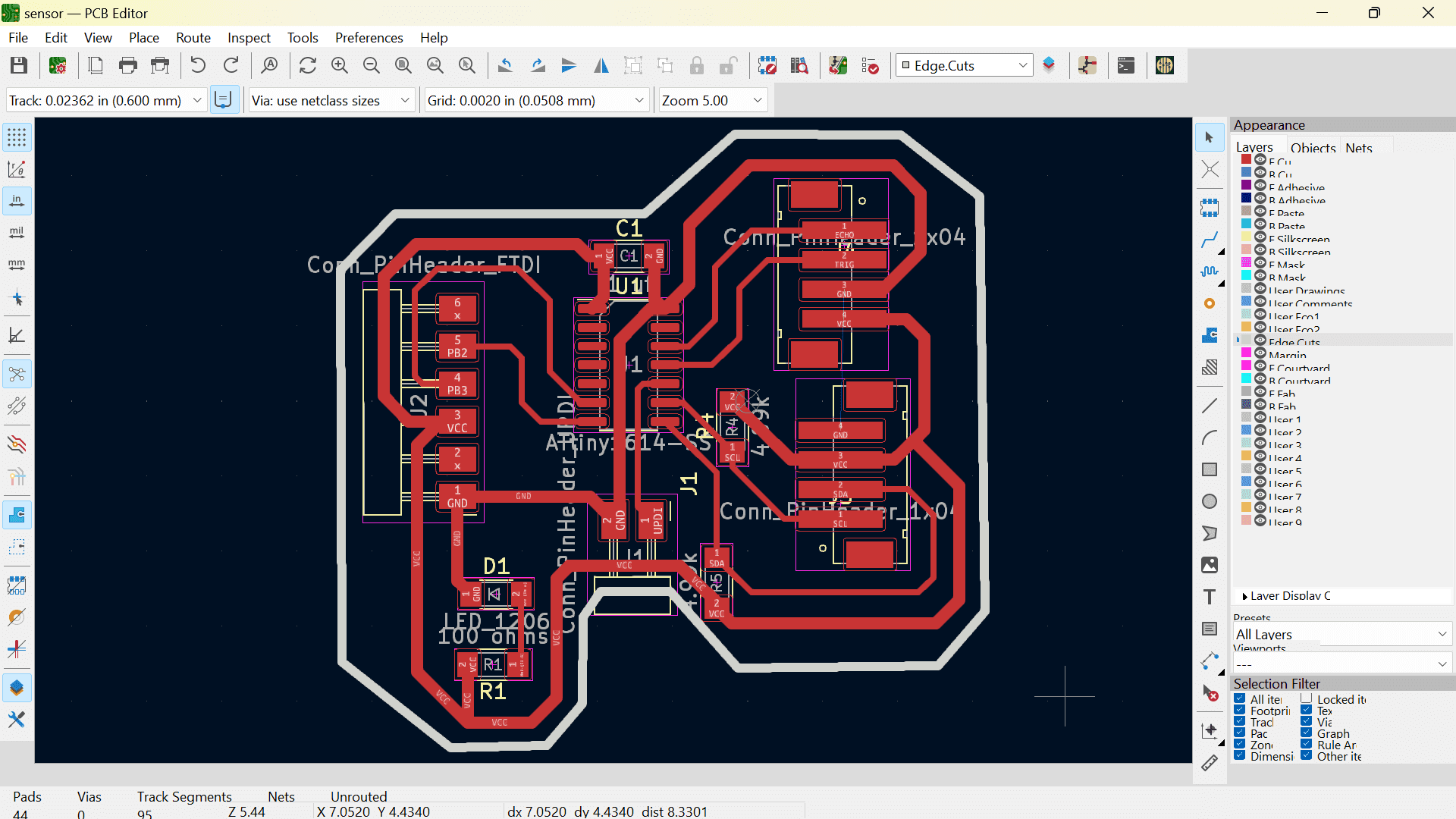
Here is my final PCB design
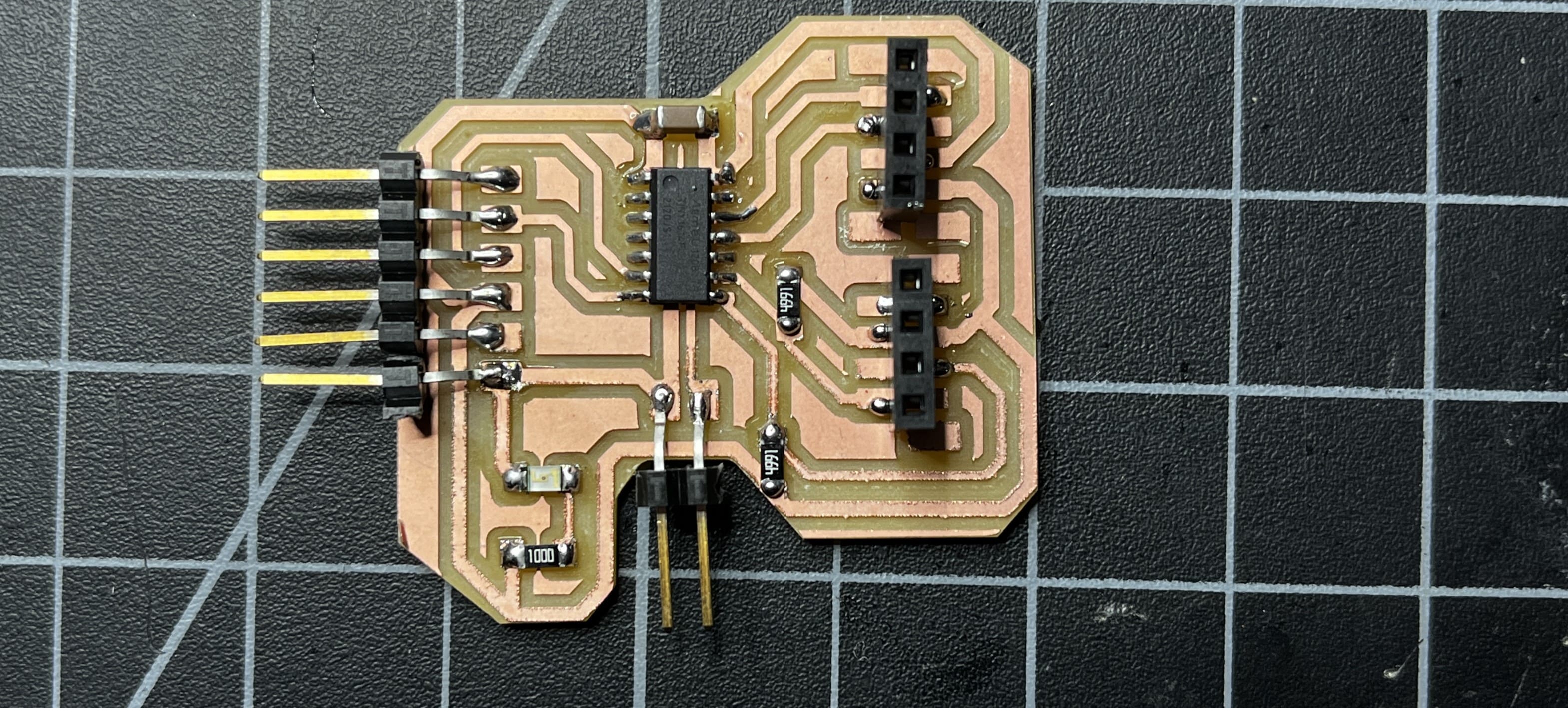
Here is my board after having it printed and soldered.
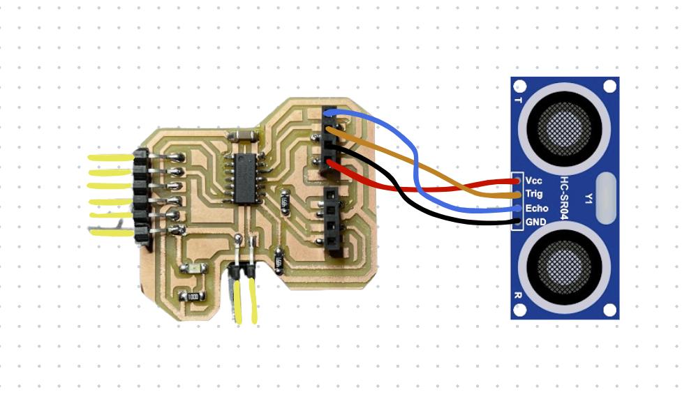
This is a clear pic of the connection between my board and the ultrasonic sensor.
Now for the ultrasonic sensor, I downloaded the library from the Arduino IDE software itself.
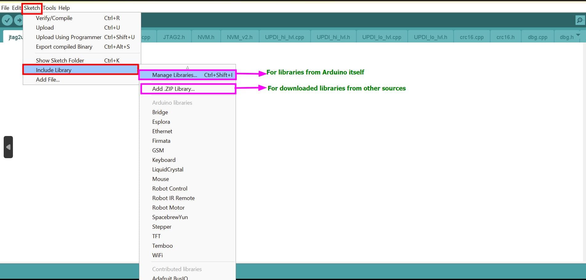
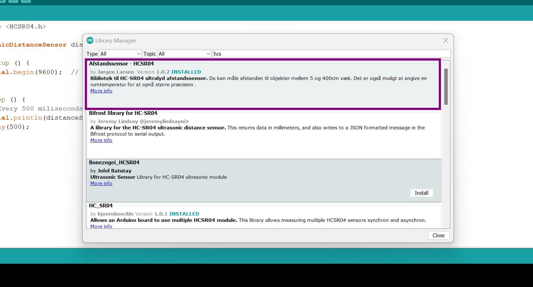
After having this library installed your software, go to files > examples and you will see that the library comes with attached examples.
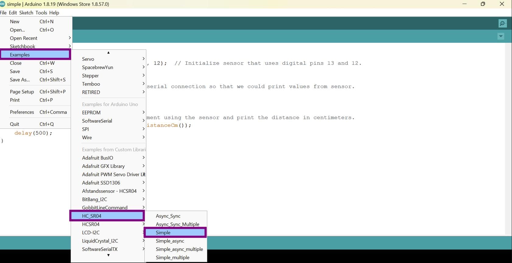
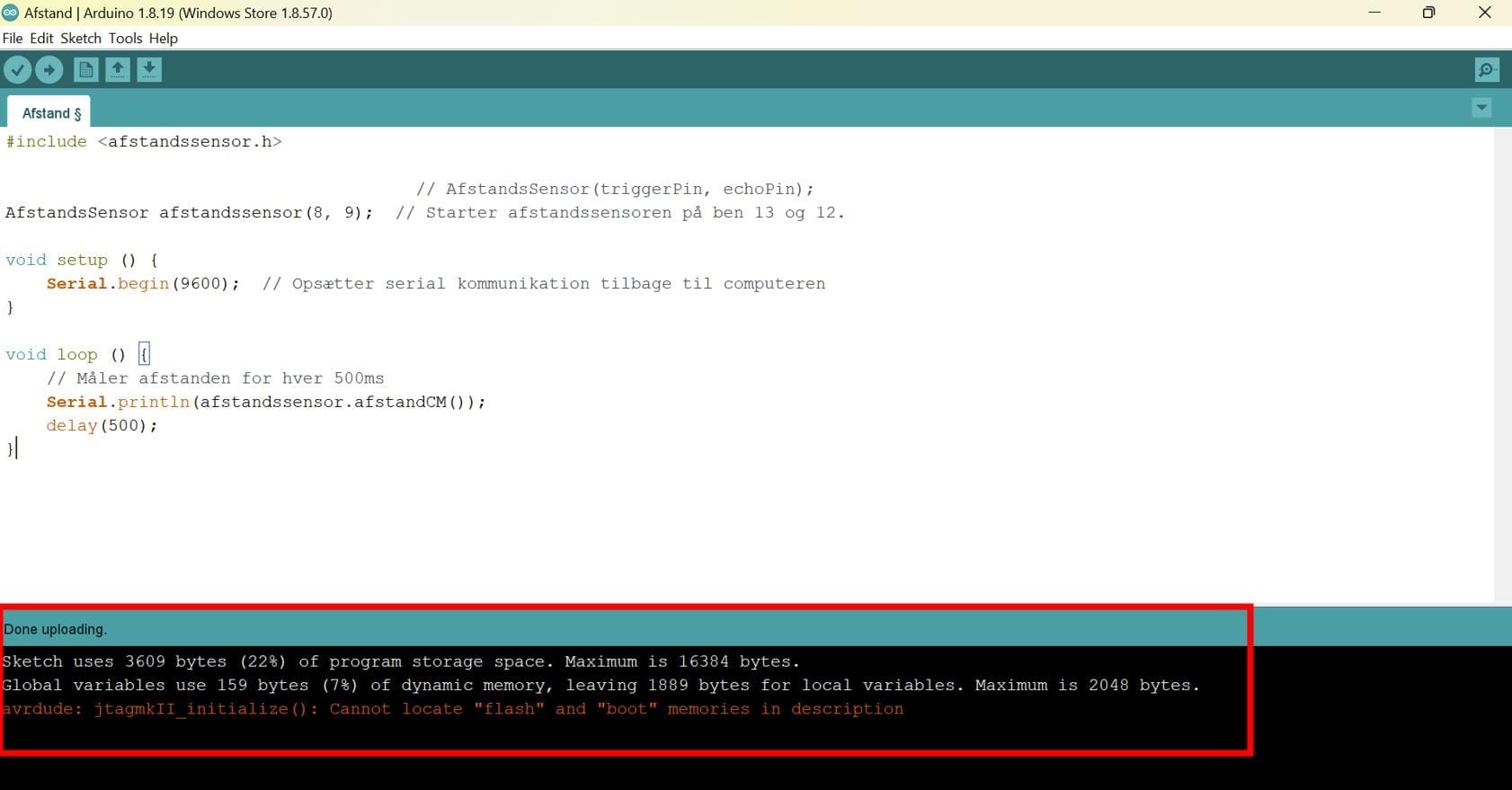
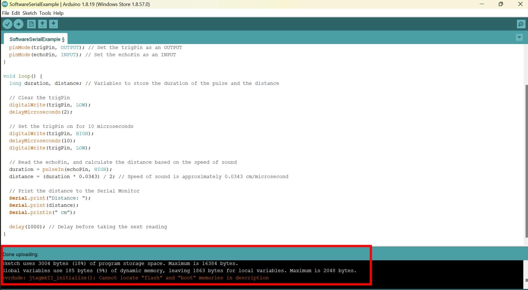
So I first chose the simple example, changed the trigger and echo pin
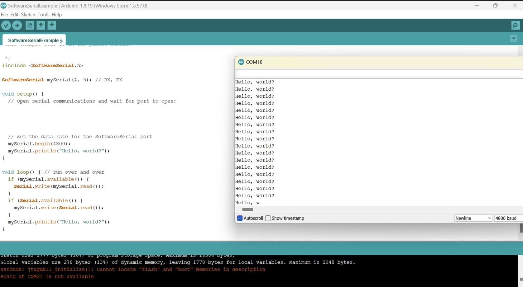
and it uploaded!!! However, my serial monitor was not working so after some research and
digging of information, I came to know that we have to use the SoftwareSerial Library through ftdi connection.
This is because the SoftwareSerial library allows serial communication on other digital pins of an Arduino board, using software to replicate the functionality (hence the name "SoftwareSerial"). It is possible to have multiple software serial ports with speeds up to 115200 bps. A parameter enables inverted signaling for devices which require that protocol. (Reference)
SoftwareSerial is a library that enables serial communication with a digital pin other than the serial port. It is possible to have multiple software serial ports with speeds up to 115200bps.
For my board, I had to use the softwareserial library and as it was already in the Arduino IDE software, I first tested the inbuilt example and it worked!!
Next, I integrated the ultrasonic sensor code to it and uploaded it via jtagupdi.
Then connected ftdi cable to my board. The serial monitor worked!!
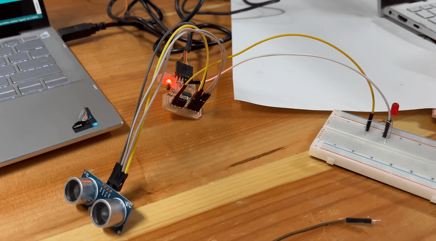
After that, I tried to make an LED light up whenever an object crosses the given threshold for the ultrasonic sensor.
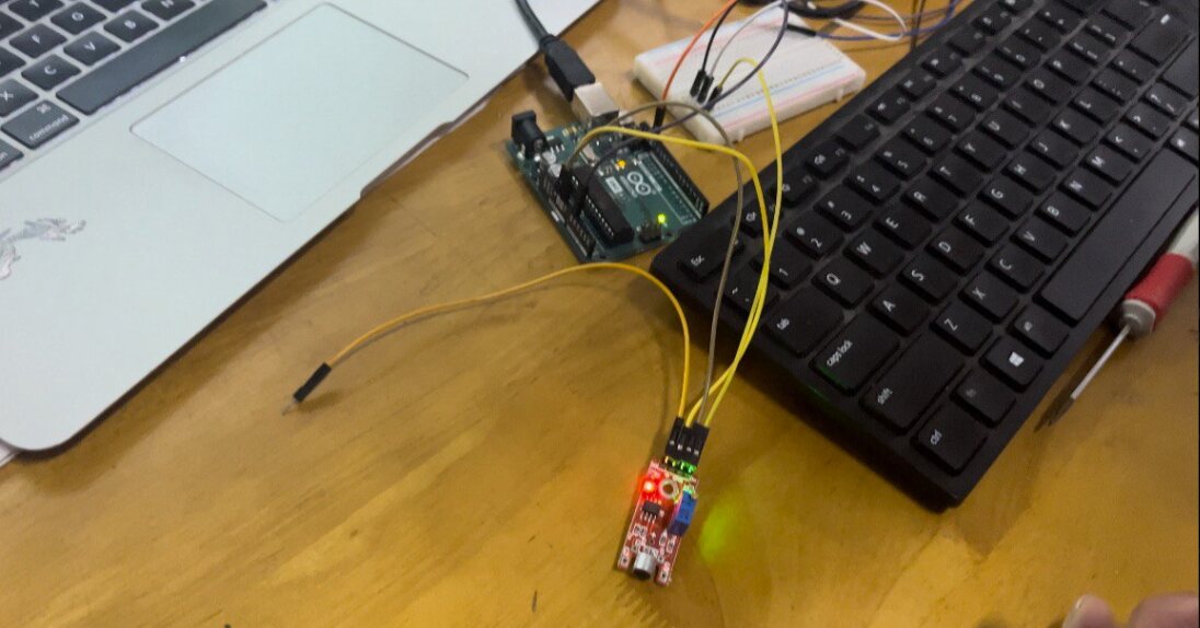
As I still have some time left, I wanted to try out the capacitive touch sensor.
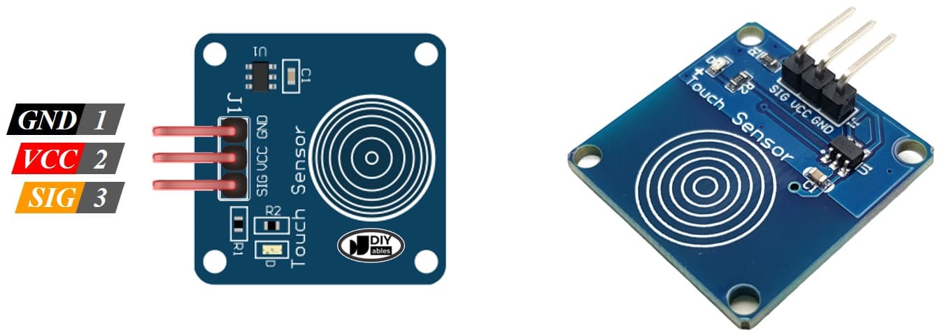
A touch sensor is a type of device that captures and records physical touch or embrace on a device and/or object. It enables a device or object to detect touch or near proximity, typically by a human user or operator.
To program this device, I got help from Damzang and her documentation as she has already done it.
I repeated the steps that I did for the ultrasonic sensor.
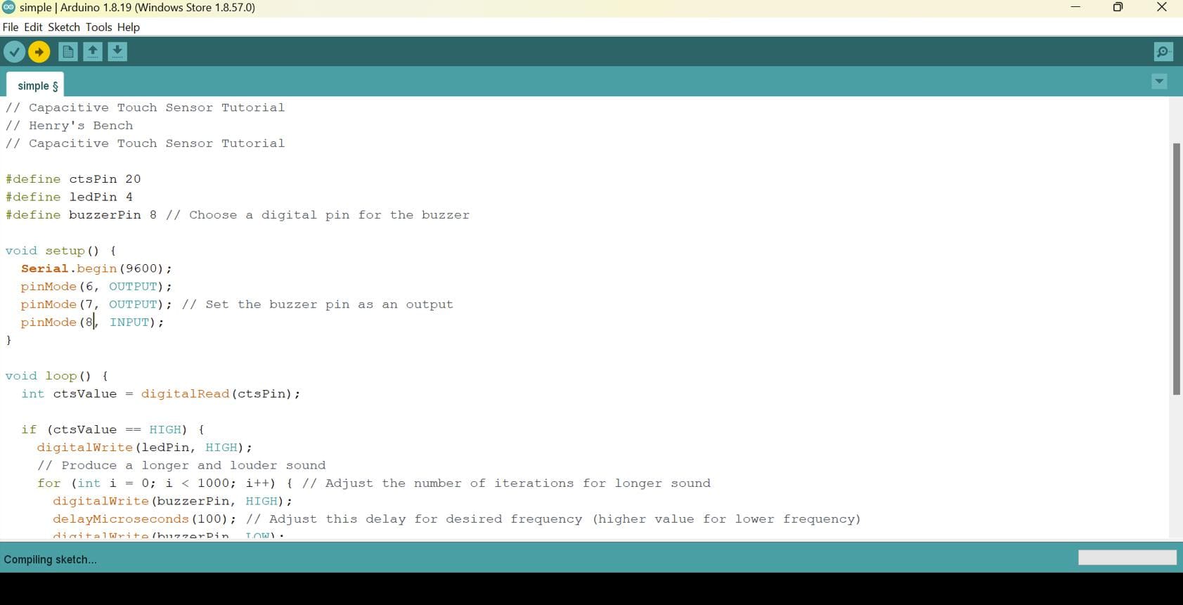
First I uploaded the following code via jtagupdi with the software serial included.
I got the following code from Damzang's documentation.
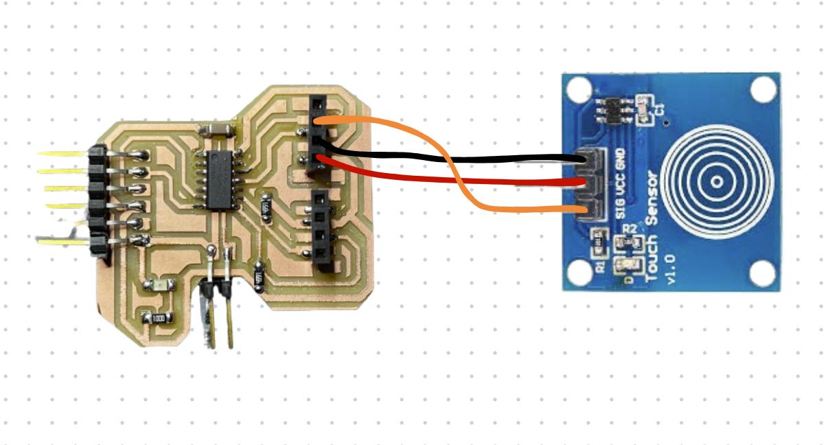
Here is the connection diagram of my board and the touch sensor that I made in Canva.
After having it uploaded to my board, I connected my board to the ftdi and opened the serial monitor. It worked!!
- Understand the working principle of ultrasonic sensors.
- Know more about the importance of SoftwareSerial library.
- Learn more functionalities of multimeters and oscilloscopes.
- Understand the working principle of capacitive touch sensors.
Zipped Board Design Files
That's it for the week!!