Figure 11-1 - Design of the microcontroller board circuit
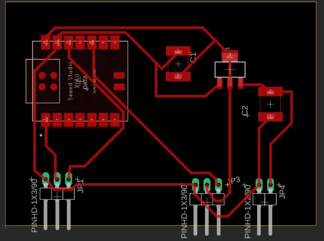
Figure 11.2 - Design of the traces of the microcontroller electronic board
Input Devices
This week I will develop a sensor that I will use in my final project. For this, I will design a board with a photovoltaic sensor and a new board for the XIAO2040 microcontroller.
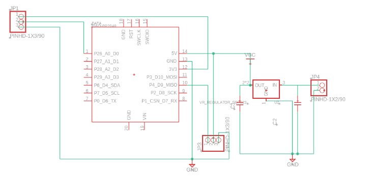
For the design of the boards, I used the Fusion program. We started by designing the electronic board that will hold the microcontroller. This board will connect to the board with the photosensor and will also be able to connect to a servo motor.
Figure 11-1 - Design of the microcontroller board circuit
Figure 11.2 - Design of the traces of the microcontroller electronic board
And we have the design of the board with the photosensor:
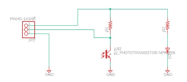
Figure 11-3 - Design of the microcontroller board circuit
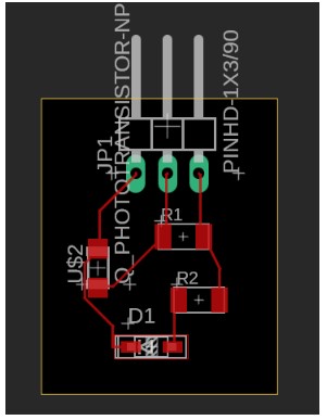
Figure 11.4 - Design of the traces of the microcontroller electronic board
I am also providing the parameters used for engraving the traces and cuts; the same parameters were used for both boards
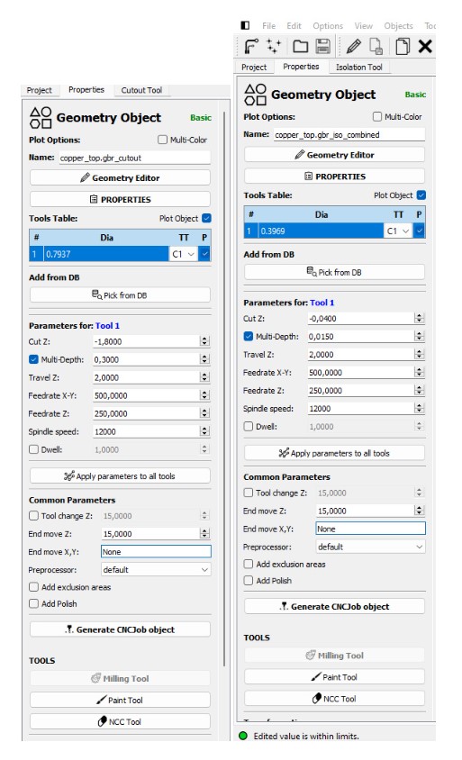
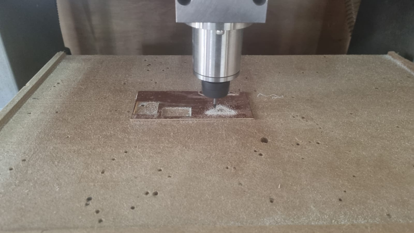
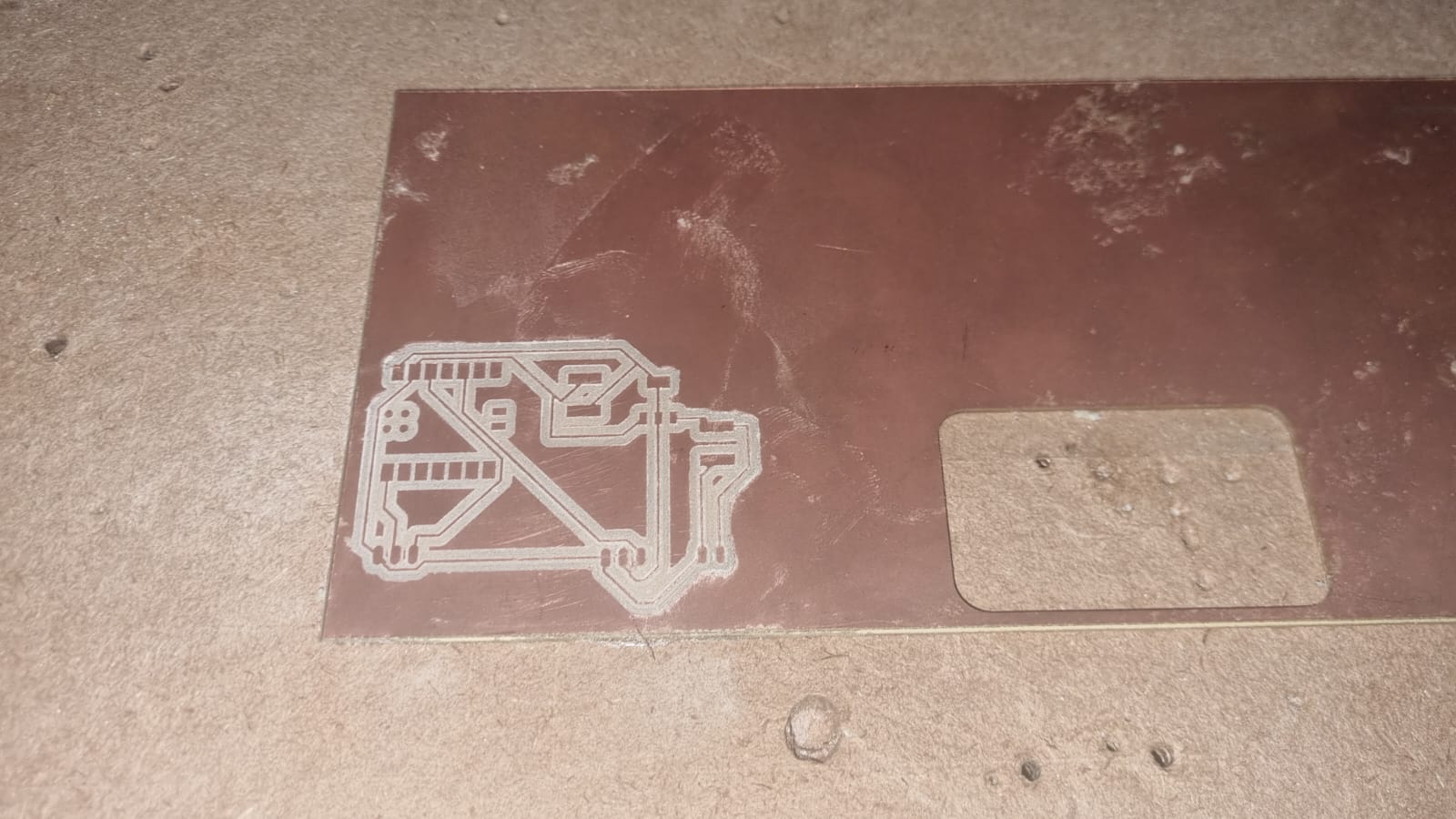
Figure 11.6 and 11.7 - Manufacturing process of the boards
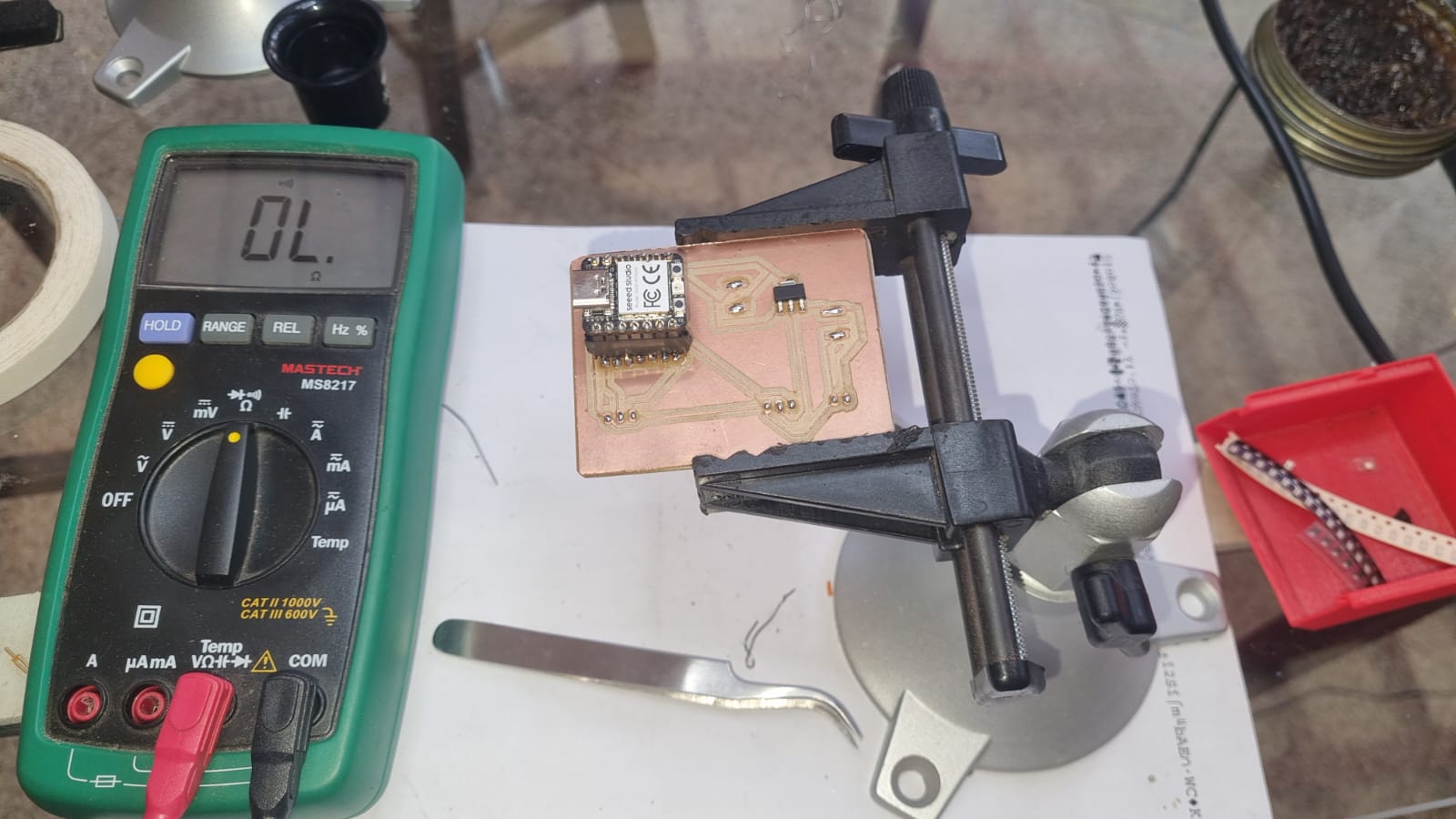
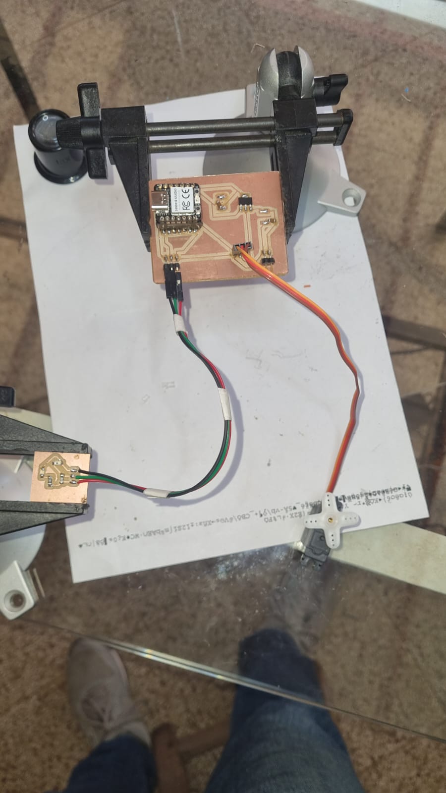
Figure 11-9 -Controller board
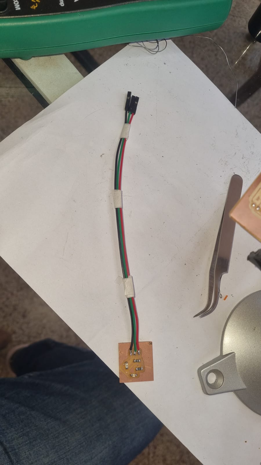
Figure 11.10 - Photoboard
Since the electronic board will be exposed to the elements in the final project, I designed a small box made with 3D filament, into which I poured epoxy resin to protect the board and allow sunlight to reach the sensor
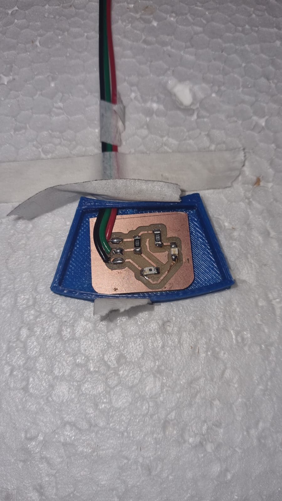
Figure 11-9 -Board in case
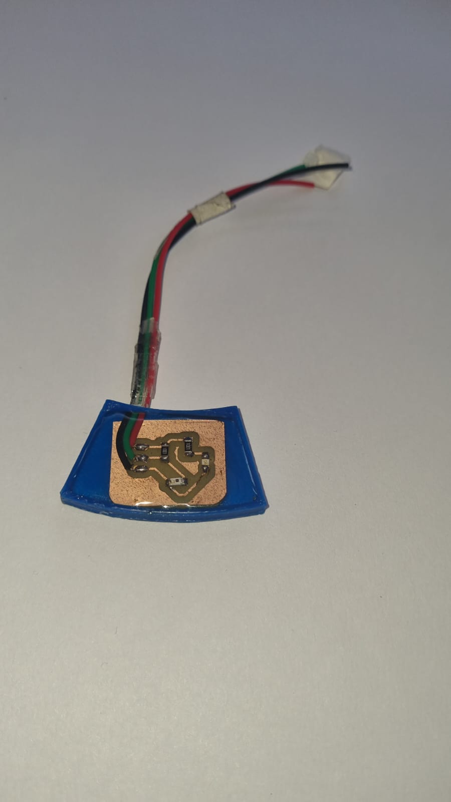
Figure 11.10 - Board protected with epoxy
To test the board, we developed a Python script that allows us to evaluate the amount of light received and send the information to a servo motor. Here is the script