-
- Week15 Overview
- My Personal assignment
- Summarize the core knowledge points of Interface and Application Programming.
- Introduction of MQTT
- Web-based MCU XiaoESP32-S3 Control
- Set up a web page to connect to Mosquitto via WebSocket
- Programming Code for Xiao ESP32S3
- Issue Summary
- The Hero Shots
- Team assignment
week15-Interface and Application Programming
Week 15 - Overview
Knowledge Points Summary
1. Programming Languages and Tools:
- Overview of different programming languages (Python, JavaScript, C) and development environments (IDEs).
2. User Interfaces:
- Techniques for creating graphical user interfaces (GUIs) and integrating user input.
3. Application Development:
- Designing and building applications that interact with hardware components.
4. Networking and Communication:
- Implementing communication protocols for devices to exchange data.
Individual Assignment:
Write an application that interfaces a user with an input and/or output device that you made.
Group Assignment:
Compare as many tool options as possible.
Reference Links
Week15 Interface and Application Programming Guide for my Fab Academy Journey.My personal assignment
1.Summarize the core knowledge points of Embeddeded Networking and Communications.
In this chapter, I learned about interface design and communication interface functions.
This allows me to control my Xiao XiaoESP32-S3 via computer or mobile applications.
1. Programming Languages and Tools:
- Overview of programming languages (Python, JavaScript, C, etc.) and development environments.
2. Device Interfaces:
- Communication protocols such as RS-232, I2C, USB, MQTT, and libraries for interfacing with hardware.
3. User Interfaces:
- Techniques for creating GUIs using libraries and frameworks like Tkinter, wxPython, Qt, and web-based interfaces.
4. Data Interfaces:
- Handling data formats (JSON, CSV) and databases (MySQL, MongoDB).
5. Graphics and Visualization:
- Using tools and libraries for 2D and 3D graphics (OpenGL, WebGL, Three.js).
6. Audio and Video:
- Integration of multimedia elements using libraries like Pygame, SDL, and Web Audio API.
2.Introduction of MQTT
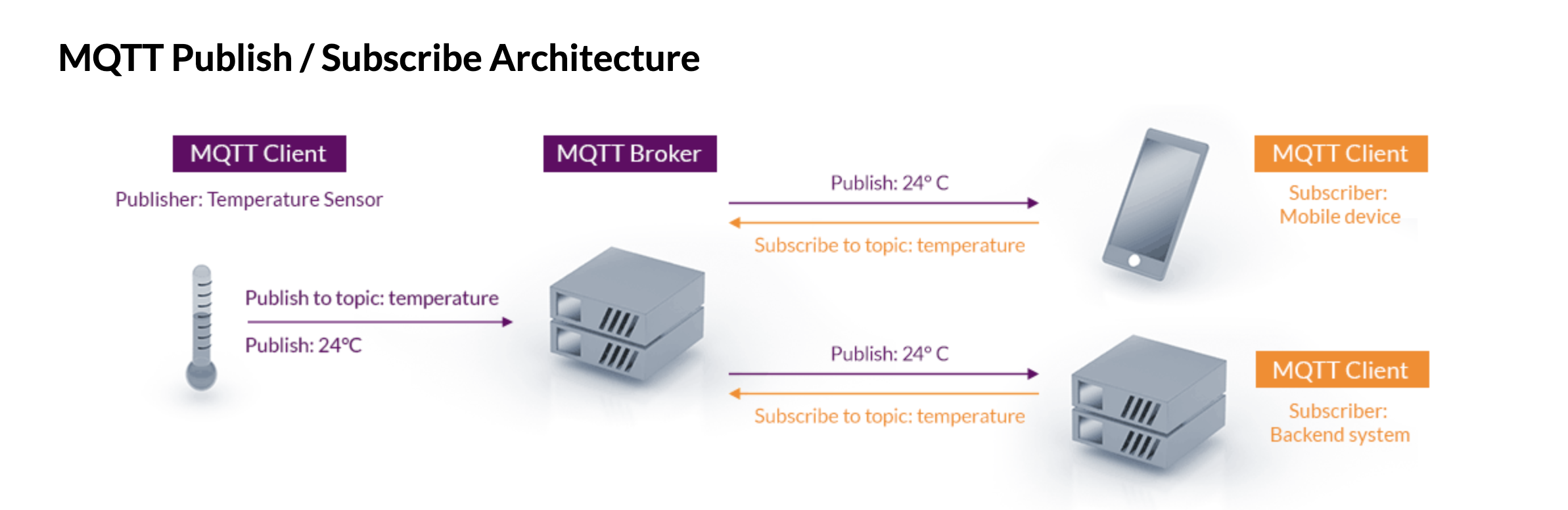
MQTT:
MQTT is an OASIS standard messaging protocol for the Internet of Things (IoT).
It is designed as an extremely lightweight publish/subscribe messaging transport that is ideal for connecting remote devices with a small code footprint and minimal network bandwidth.
MQTT today is used in a wide variety of industries, such as automotive, manufacturing, telecommunications, oil and gas, etc.

Here's how it works:
1. Clients connect to a broker and can subscribe to topics.
2. Clients publish messages to a broker, specifying a topic.
3. The broker then forwards these messages to all clients subscribed to that topic.
4. This model allows for messages to be delivered to multiple consumers without the need for clients to know each other, providing high levels of scalability and reliability in message delivery.
My MQTT connection plan:
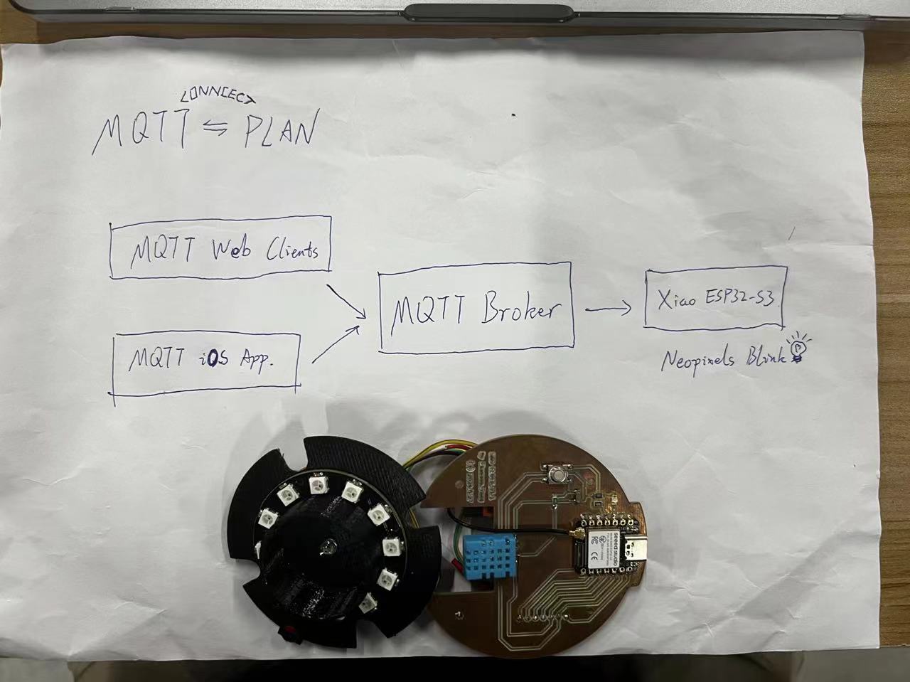
I plan to use both web and mobile platforms to control the Xiao.
Ultimately, this setup will enable remote control to light up the NeoPixels.
Setup I need to make the following two preparations:
1. Obtain a broker.
- I will use the public broker provided by Fab-Academy.
Get the broker information here.
For specific connection to the Fab Academy MQTT broker, use the following details:
Broker URL: mqtt.fabcloud.org
Port: 1883
Username: fabacademy
Password: fabacademy
Channel/Topic: fabacademy/
You can add your own sub-topic within fabacademy to keep messages for your application only (e.g., your lab name and/or username, like fabacademy/paris-john).
Websocket: wss://mqtt.fabcloud.org:8083
Visit Mosquitto's official website for general information.
MQTT SoftwareFind the software for here.
For web:
For iOS:
3.Web-based MCU XiaoESP32-S3 Control
I have found a tutorial for setting up MQTT.
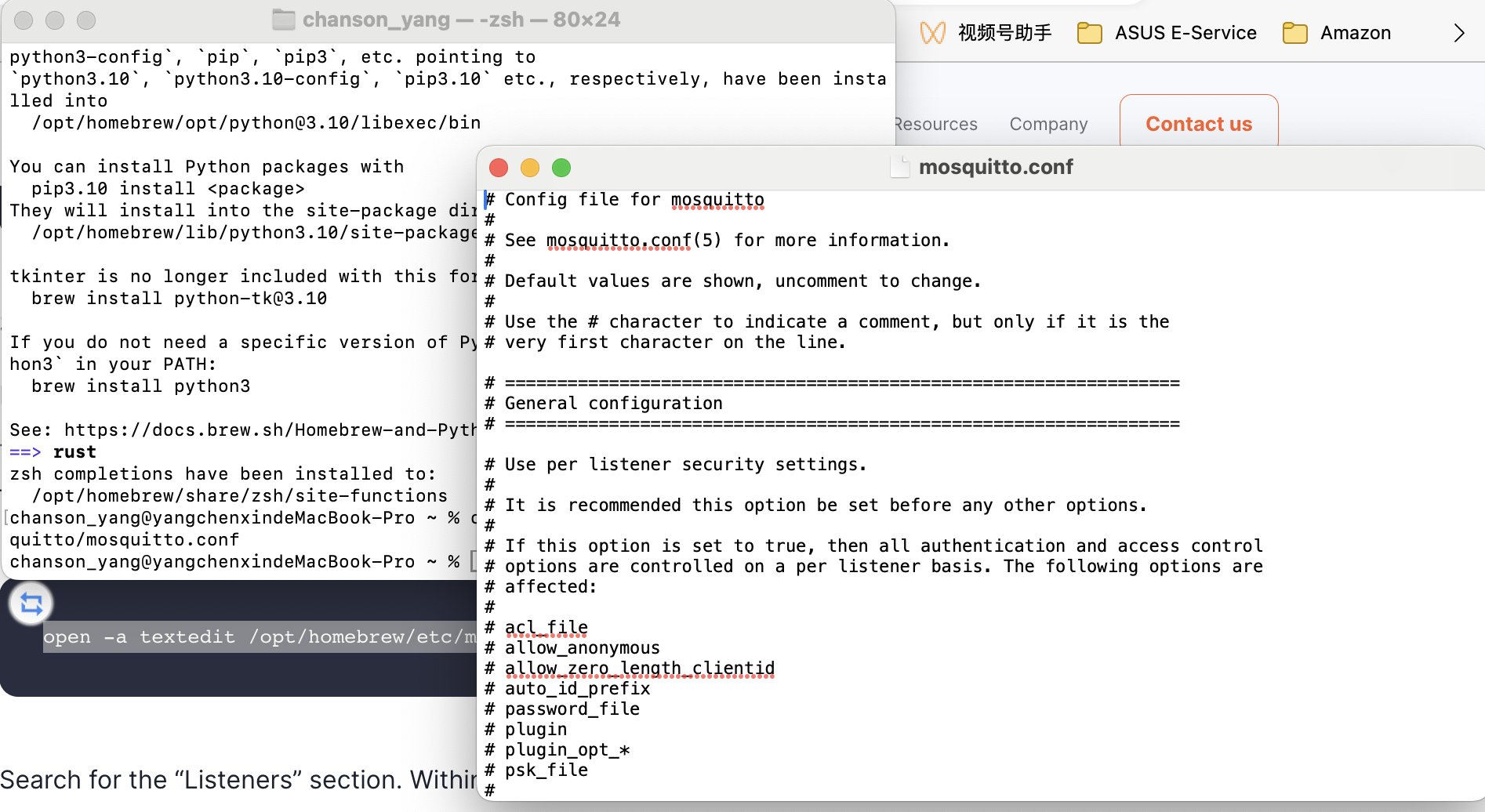
Open the
Find the "Configuring Mosquitto MQTT broker over WebSockets for MacOS"
Download Brew and install it.https://github.com/Homebrew/brew/releases/tag/4.3.8
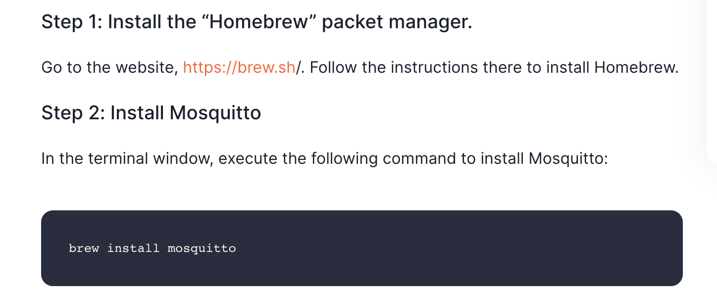
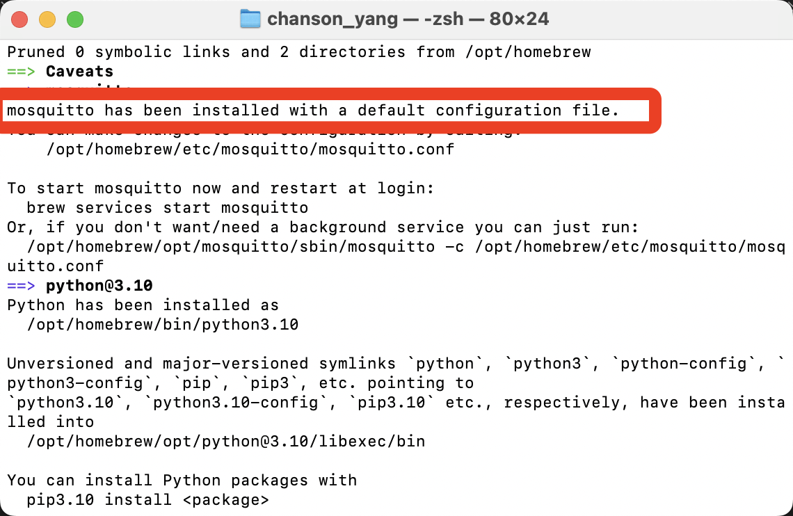
Install Mosquitto:
brew install mosquitto
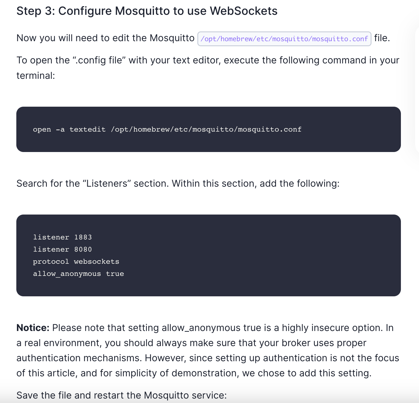
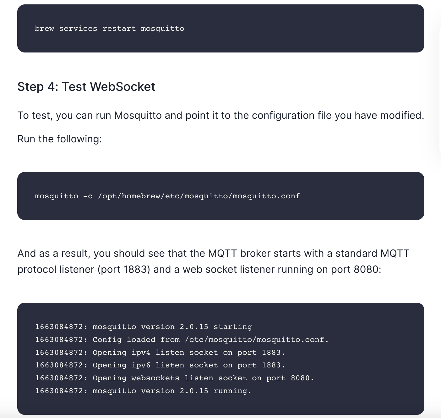
Setup Mosquitto:
Test WebSockets:
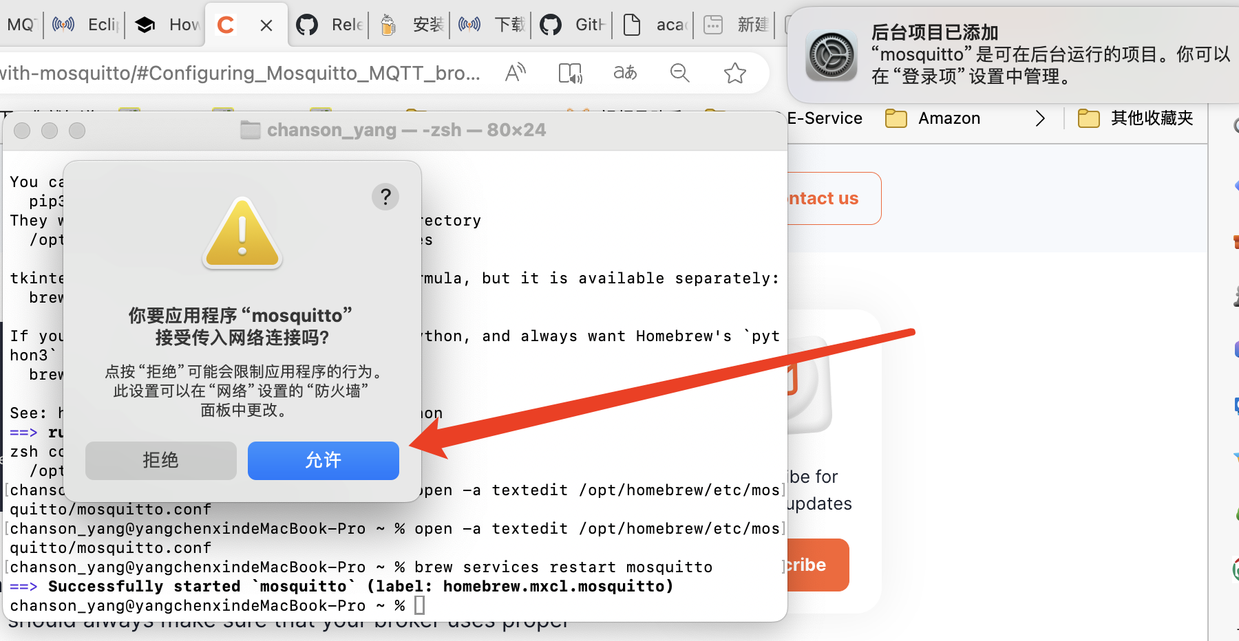
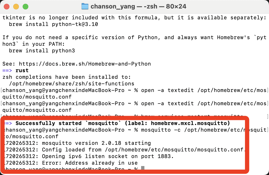
ps:There's a problem with the Setup,I find some solutions that it need to kill the process.
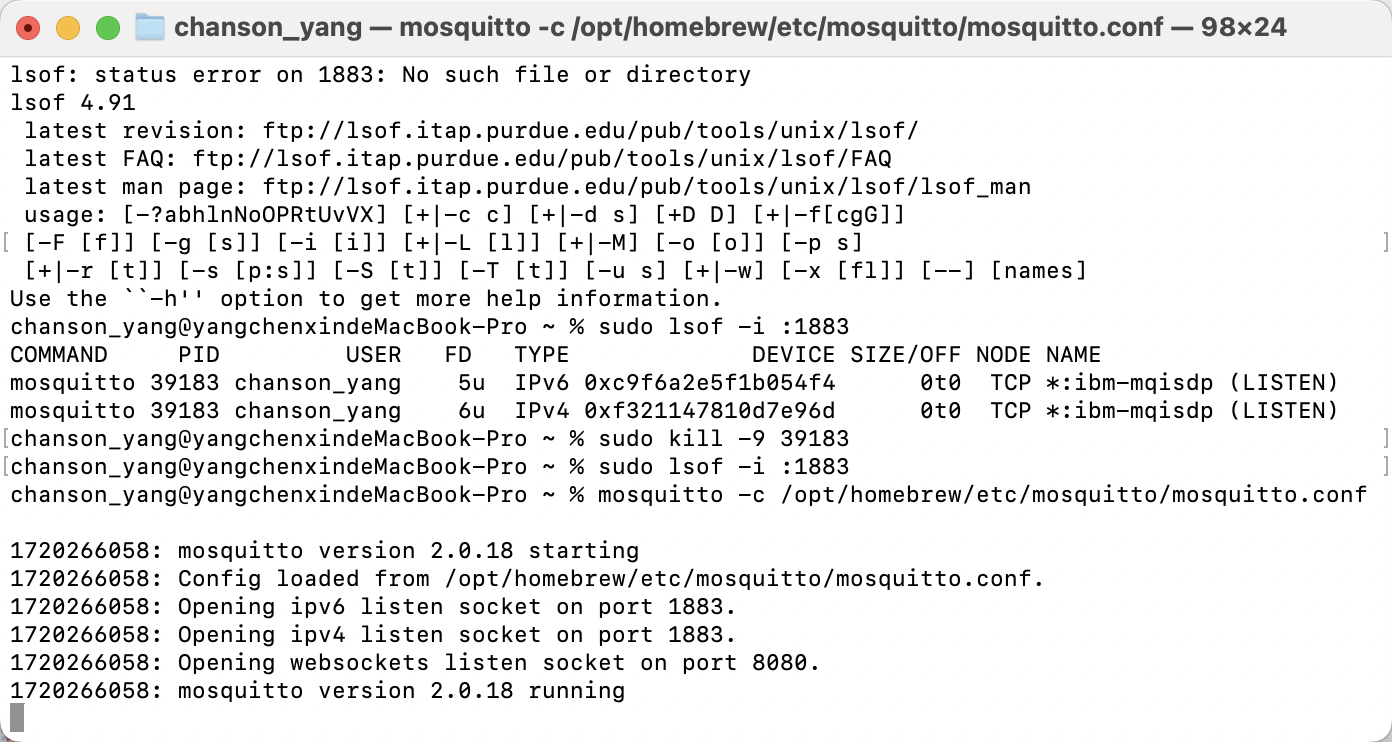
Finally,Setup!
I have already deployed Mosquitto.
Next, how should I create a web interface to control the MCU?
I asked ChatGPT for advice.
To communicate with MQTT from a webpage using JavaScript and the Paho MQTT library, follow these steps:
- Include the Paho MQTT Library: Add the Paho MQTT client library to your webpage. You can include it directly from a CDN or download and host it yourself.
- Create MQTT Client:
- Initialize the MQTT client by specifying the broker’s URL and port.
- Provide a unique client ID for the connection.
- Connect to MQTT Broker:
- Set up connection options such as username, password (if required), and SSL settings for secure connections.
- Use the
connect()method with your options to establish the connection to the MQTT broker.
- Handle Connection Events:
- Implement callbacks for connection success and failure.
- Handle successful connection by subscribing to topics and setting up message arrival handling.
- Subscribe to Topics: Use the
subscribe()method to listen to topics of interest. - Send and Receive Messages:
- Publish messages using the
send()orpublish()methods. - Implement a message handler function to process incoming messages.
- Publish messages using the
- Disconnect: Cleanly disconnect from the broker when the webpage is closed or the connection is no longer needed.

Test the MQTT connection in local
I open 2 terminals, one for the pub and one for the sub.
then I run the following command in the pub terminal:
mosquitto_pub -h localhost -t "Test" -m "Hello"and then run the following command in the sub terminal:
mosquitto_sub -h localhost -t "Test"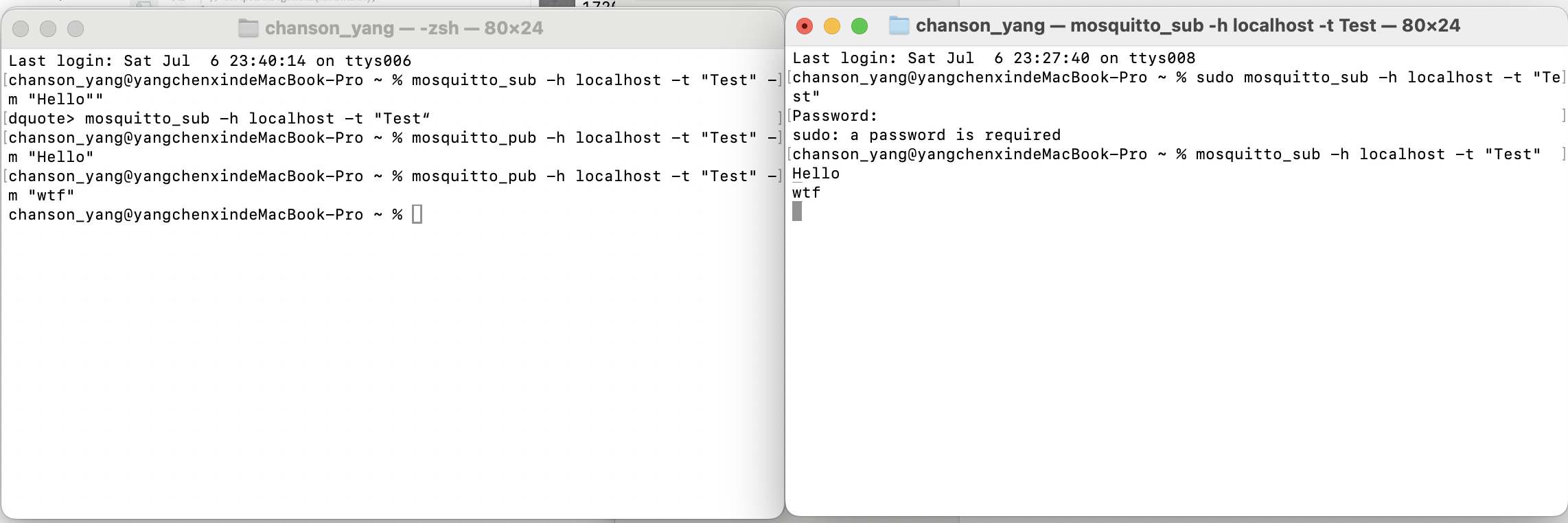
OK!,it's now time to create a web interface to control the MCU.
Firstly, I need to create a web page that can connect to the MQTT broker and subscribe to the topic.
I will use JavaScript and the Paho MQTT library to achieve this.
Link to MQTT.html
4.Set up a web page to connect to Mosquitto via WebSocket
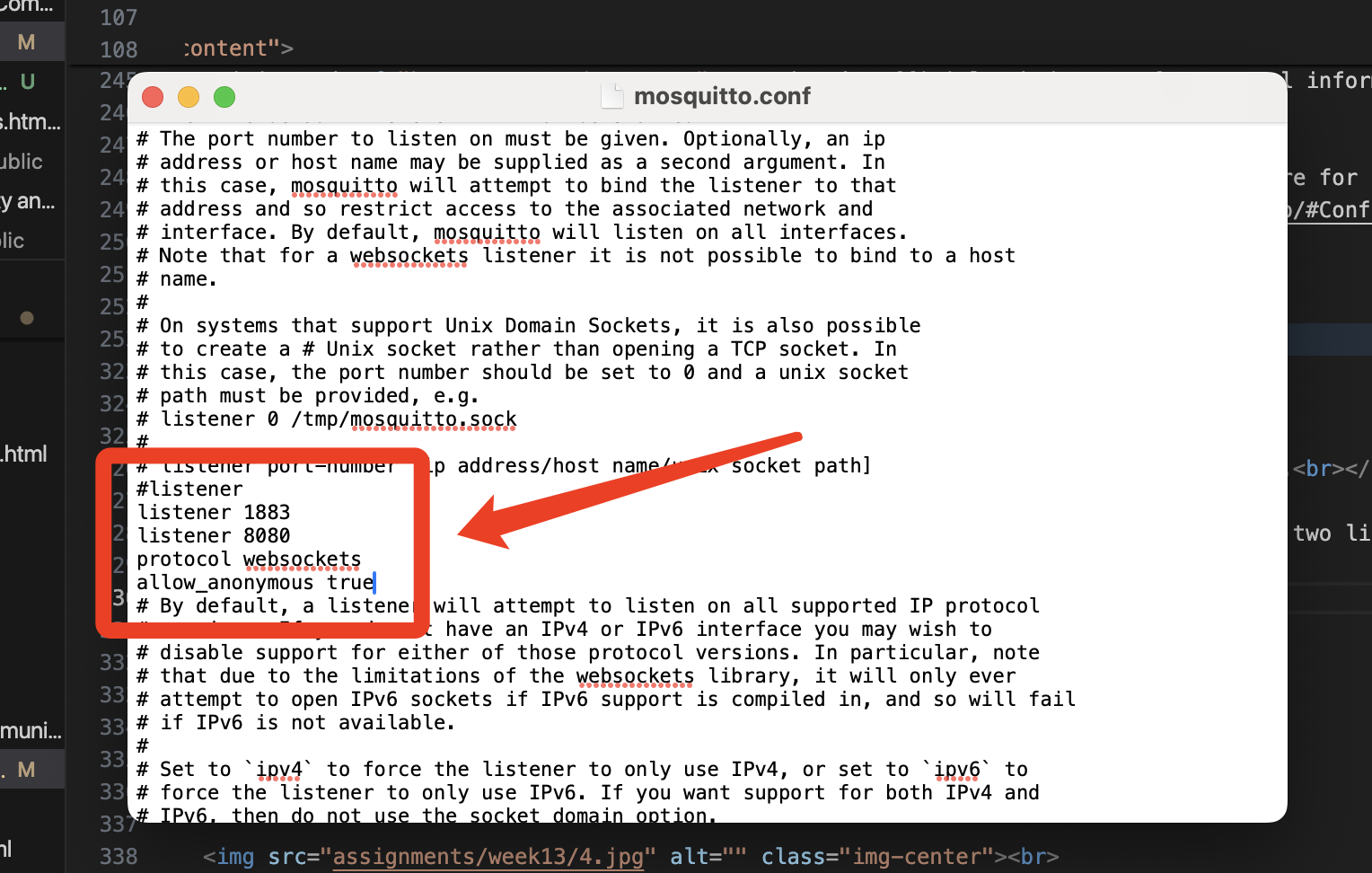
1. I need to locate the mosquitto.config file again and set up the listening port.
- My classmates Karthrine give me the following Important massages is that to add two listeners, one on 1883 port for the Xiao ESP32S3, another 8080 for the webbrowser using websocket protocol.
- I have checked the file and confirmed that my settings are correct.
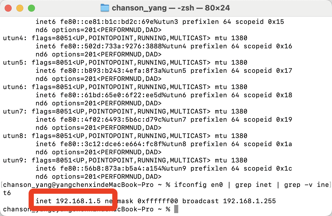
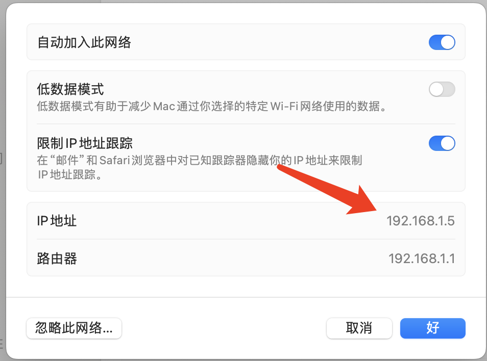
2. Find my IP address.
- I use the command "ifconfig en0 | grep inet | grep -v inet6" to find my IP address.
- I found my IP address is 192.168.1.5
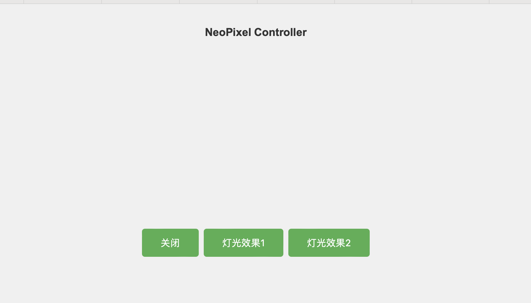
3.Programming the code for web page to connect to Mosquitto via WebSocket.
>Several functions have been defined to publish messages.There are three functions that correspond to controlling the LED in three different states: turning off the light (sending the ‘OFF’ message), light effect 1 (sending the ‘EFFECT1’ message), and light effect 2 (sending the ‘EFFECT2’ message).
These functions send the respective control commands to the topic through the publishMessage function.
U can open this page to see the control of LED.
Link to MQTT-Test.html
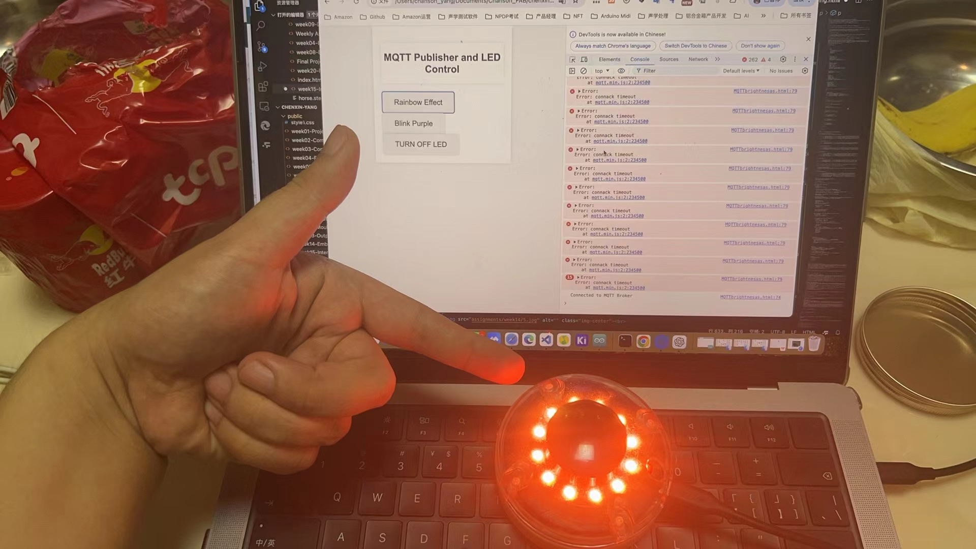
Also Here is web program directly show in this page,it can control the LED Dirctly:
<!DOCTYPE html>
<html>
<head>
<style>
body {
font-family: Arial, sans-serif;
background-color: #f4f4f4;
margin: 0;
padding: 0;
}
h2 {
color: #333;
text-align: center;
padding: 20px 0;
background-color: #fff;
box-shadow: 0 0 10px rgba(0, 0, 0, 0.1);
}
button {
padding: 15px 30px;
font-size: 18px;
border: none;
border-radius: 5px;
cursor: pointer;
box-shadow: 0 0 5px rgba(0, 0, 0, 0.2);
transition: background-color 0.3s ease;
}
button:hover {
background-color: #4CAF50;
color: #fff;
}
#container {
width: 50%;
margin: 0 auto;
padding: 20px;
background-color: #fff;
box-shadow: 0 0 10px rgba(0, 0, 0, 0.1);
}
#brightnessValue {
width: 100px;
padding: 10px;
font-size: 18px;
border-radius: 5px;
border: 1px solid #ccc;
}
</style>
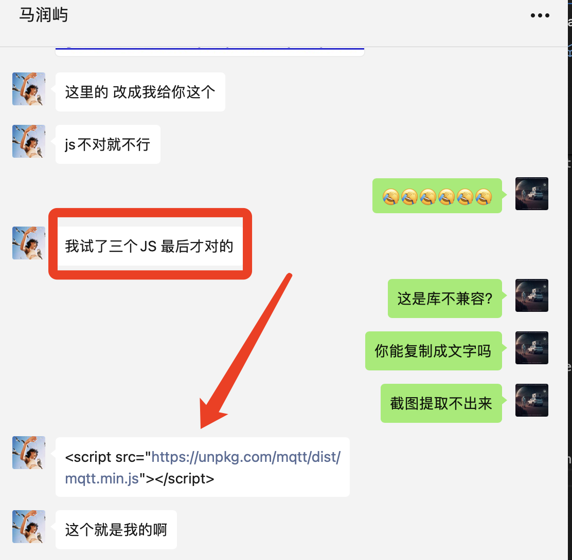
<script src="https://unpkg.com/mqtt/dist/mqtt.min.js"></script>
</head>
<body>
<div id="container">
<h2>MQTT Publisher and LED Control</h2>
<button onclick="rainBowEffect()">Rainbow Effect</button>
<button onclick="blinkEffect()">Blink Purple</button>
<button onclick="turnOffLed()">TURN OFF LED</button>
</div>
<script>
// MQTT Broker 配置
const brokerUrl ='mqtt://192.168.1.5:8080';
const topic = 'xiao esp32s3/neopixels';
// 创建 MQTT 客户端
const client = mqtt.connect(brokerUrl);
// 连接成功的回调
client.on('connect', () => {
console.log('Connected to MQTT Broker');
});
// 错误处理的回调
client.on('error', (error) => {
console.error('Error:', error);
});
// 点亮 rainbow 效果的函数
function rainBowEffect() {
client.publish(topic, 'EFFECT1');
}
// 设置 blink
function blinkEffect() {
client.publish(topic, 'EFFECT2');
}
// 熄灭 LED 的函数
function turnOffLed() {
client.publish(topic, 'OFF');
}
</script>
</body>
</html>
5.Programming Code for Xiao ESP32S3
I get the method from ChatGPT.
1. Introduction of Libraries and Initial Settings
- Import Libraries: The code starts with importing necessary libraries to support WiFi and MQTT functionalities, crucial for connecting the device to the internet and communicating via MQTT.
- WiFi Network Details: Defines variables for the WiFi network's SSID and password, enabling the device to connect to the internet.
- MQTT Server Details: Specifies the MQTT server address and port, necessary for establishing a connection with the MQTT broker to send and receive messages.
- LED Pin Configuration: Defines the pin numbers connected to the LEDs, setting the foundation for controlling the LEDs based on MQTT messages.
2. Callback Function
- Message Handling: Defines a callback function to handle received MQTT messages. This function is triggered whenever there is a new message on the subscribed topics.
- Parsing and Action: Inside the callback, the message payload is parsed, and actions are determined based on content and topic, such as turning on or off the LED, or adjusting its brightness if the topic indicates LED control.
3. Reconnection Mechanism
- Reconnect Function: The reconnect function is crucial for maintaining a stable connection with the MQTT server. If the connection is lost, this function attempts to reconnect.
- Continuous Connection Attempts: Includes a loop that continues to attempt reconnection until successful.
- Resubscribe: Once reconnected, it also resubscribes to relevant topics to ensure no messages are missed during disconnections.
4. Setup Routine
- Serial Communication: The setup function initializes serial communication, useful for debugging by sending and receiving data through the serial port.
- LED Pin Setup: Configures the defined LED pins as output, preparing for operation.
- WiFi Connection: Attempts to connect to the defined WiFi network.
- MQTT Configuration: It configures the MQTT client with server details and registers the callback function to handle incoming messages.
5. Main Loop
- Connection Check: The loop function continuously checks if the MQTT client is still connected.
- Reconnection Call: If the connection is lost, it calls the reconnect function.
- Message Handling: Ensures the MQTT client continues to process any incoming messages by calling functions that handle the client's internal state and message queue.
This structure provides a robust framework for IoT devices to perform tasks such as remote control of the device through MQTT messages.
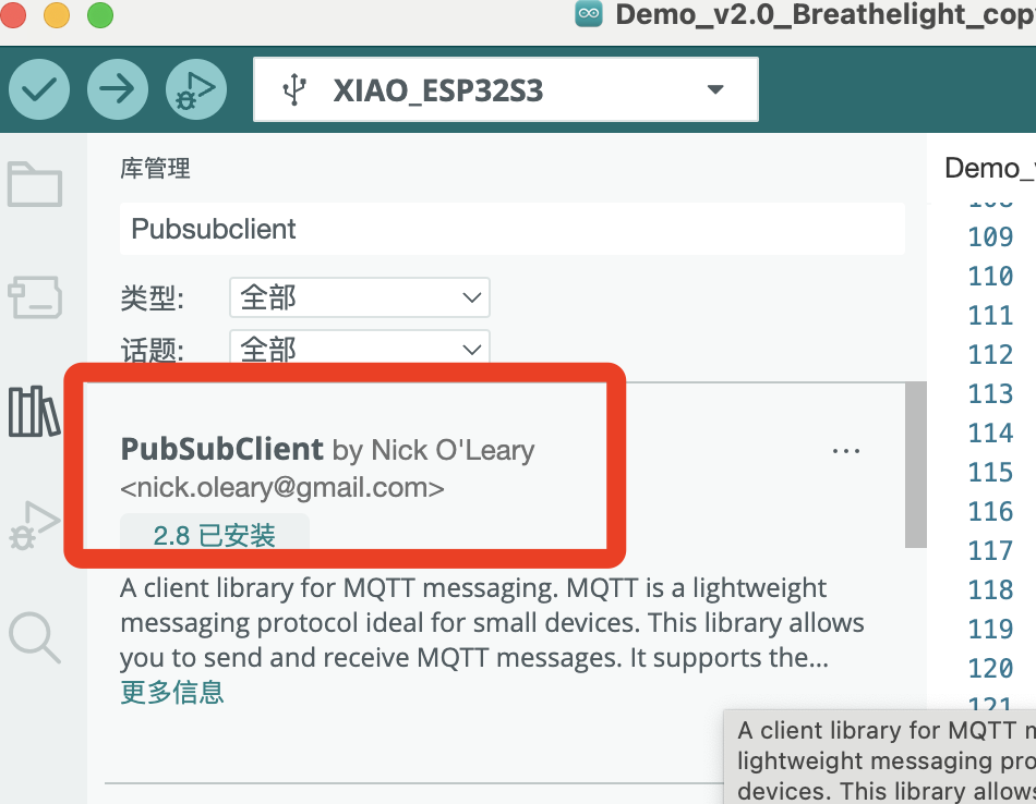
Firstly,I need install the necessary libraries
I chose the following libraries:
- PubSubClient
Example Program Overview
This example program demonstrates how to control an LED using the Xiao ESP32S3 through WiFi and MQTT. The program includes setting up a WiFi connection, connecting to an MQTT server, and controlling the LED based on subscribed MQTT messages.
#include <WiFi.h>
#include <PubSubClient.h>
#include <Adafruit_NeoPixel.h>
const char* ssid = "4536251"; // 替换为你的WiFi名称
const char* password = "EACTJB159357"; // 替换为你的WiFi密码
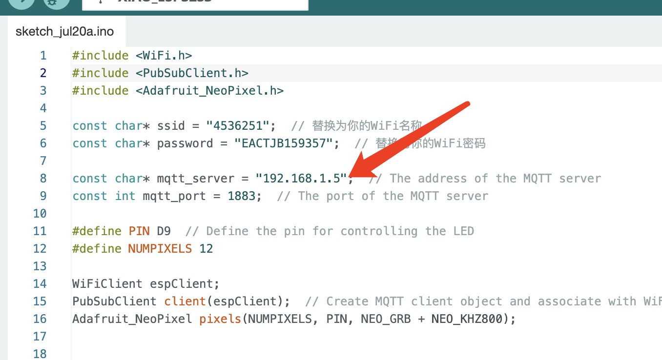
const char* mqtt_server = "192.168.1.5"; // The address of the MQTT server
const int mqtt_port = 1883; // The port of the MQTT server
#define PIN D9 // Define the pin for controlling the LED
#define NUMPIXELS 12
WiFiClient espClient;
PubSubClient client(espClient); // Create MQTT client object and associate with WiFi client
Adafruit_NeoPixel pixels(NUMPIXELS, PIN, NEO_GRB + NEO_KHZ800);
void setup_wifi() {
Serial.begin(115200);
delay(10);
Serial.println("Connecting to WiFi...");
WiFi.begin(ssid, password);
while (WiFi.status() != WL_CONNECTED) {
delay(500);
Serial.print(".");
}
Serial.println("WiFi connected");
Serial.println("IP address: ");
Serial.println(WiFi.localIP());
}
void callback(char* topic, byte* payload, unsigned int length) {
String message;
for (int i = 0; i < length; i++) {
message += (char)payload[i];
}
if (String(topic) == "xiao esp32s3/neopixels") {
if (message == "OFF") {
pixels.clear(); // 关闭所有LED
} else if (message == "EFFECT1") {
for (int j = 0; j < 256; j++) { // 彩虹循环效果
for (int i = 0; i < pixels.numPixels(); i++) {
pixels.setPixelColor(i, pixels.ColorHSV(j * 65536 / 256));
}
pixels.show();
delay(20);
}
} else if (message == "EFFECT2") {
for (int i = 0; i < pixels.numPixels(); i++) { // 单色循环亮灭效果
pixels.setPixelColor(i, pixels.Color(150, 0, 255)); // 设置为紫色
pixels.show();
delay(250);
pixels.clear();
pixels.show();
delay(250);
}
}
}
}
void reconnect() {
while (!client.connected()) {
if (client.connect("ESP32Client")) {
Serial.println("MQTT Connected"); // 添加的MQTT连接成功的提示
client.subscribe("xiao esp32s3/neopixels");
} else {
Serial.print("Attempting MQTT connection..."); // 提示正在尝试连接MQTT服务器
delay(5000);
}
}
}
void setup() {
setup_wifi(); // 设置WiFi连接
client.setServer(mqtt_server, mqtt_port); // 设置MQTT服务器
client.setCallback(callback); // 设置MQTT回调函数
pixels.begin(); // 初始化Neopixels
// 设置所有Neopixels为蓝色并显示
for (int i = 0; i < pixels.numPixels(); i++) {
pixels.setPixelColor(i, pixels.Color(0, 0, 255)); // RGB颜色:纯蓝色
}
pixels.show(); // 更新显示以应用设置的颜色
}
void loop() {
if (!client.connected()) {
reconnect();
}
client.loop();
}
Code Explanation
- Include Necessary Libraries: Uses the WiFi library and the PubSubClient library (a popular Arduino MQTT library).
- Define Network and MQTT Parameters: Includes the SSID and password for WiFi, as well as the address and port for the MQTT server.
- Set Up LED Pin: Defines the GPIO pin used to control the LED.
- Initialize WiFi and MQTT Connection: Sets up the WiFi connection and initializes the MQTT client.
- MQTT Message Handling: Controls the state of the LED based on the received messages.
Initial Setup for MQTT Terminal
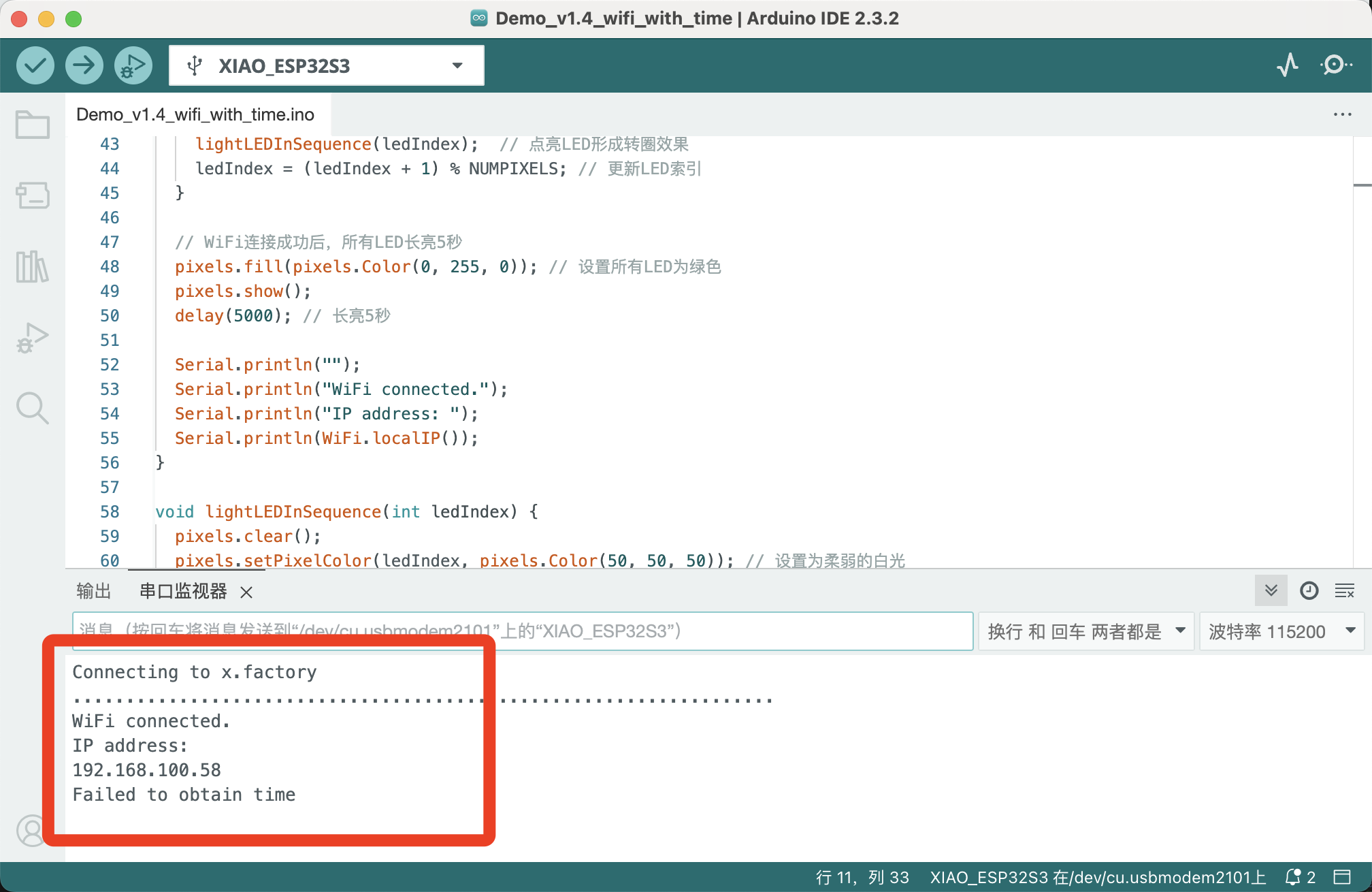
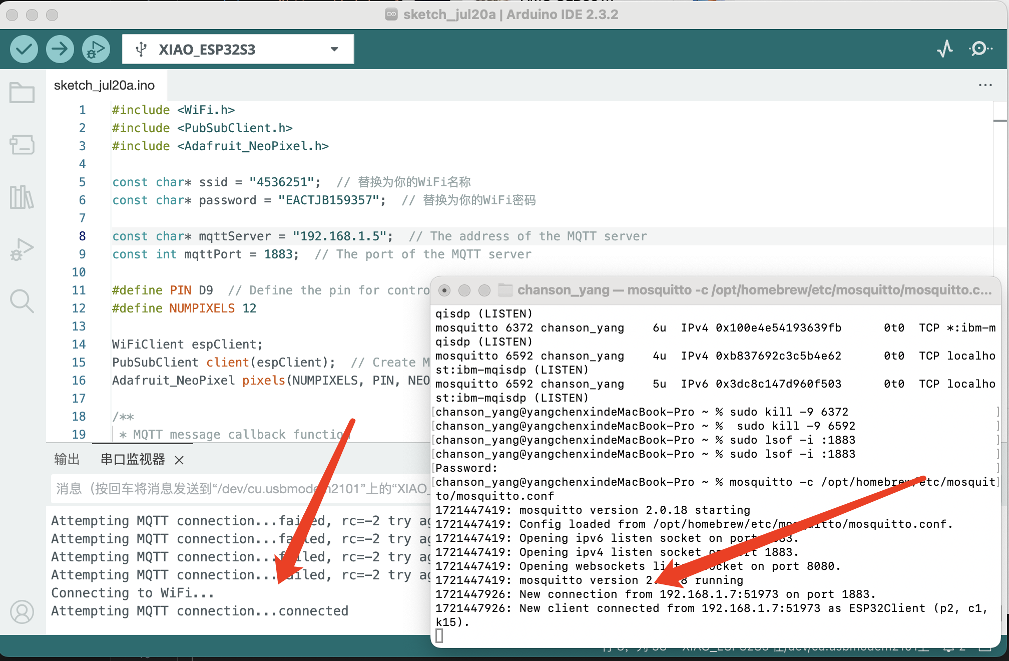
First, it is essential to set up the MQTT terminal on the computer and ensure it is running. Importantly, make sure that no other processes are occupying port 1883.
Next, upload the program to the small ESP32. After connecting to WiFi, successful connection messages will appear simultaneously in the serial console window and on the computer terminal.
Next, we can attempt to control the xiao ESP32s3 using a web-based application. This allows for remote interaction with the device from any web-enabled interface.
This video demonstrates my entire MQTT project:
Finally, we can use the MQTT terminal to monitor the messages being sent by the device.
6.Issue Summary
MQTT Debugging Challenges Summary
Throughout the process of debugging MQTT, I encountered several issues. I am grateful for my classmate Kathryn, who helped me solve many of these problems. The main issues were as follows:
Issue 1: Despite all aspects of the code being correct, unstable network conditions caused IP changes, leading to connection failures. The solution was to regularly check and correct the IP settings to the accurate values.
Issue 2: After uploading local code to the ESP32, it consistently failed to connect to the server. Katherine's advice was to ensure that the port number was not included in the blocker's address in the device setup. Correcting this allowed the ESP32 to successfully connect to the terminal.
Issue 3: Even though the terminal connection was successful, we were unable to control the ESP32 via the web interface. This problem might be due to incompatibilities arising from the use of Java libraries within HTML.
Issue 4: The MQTT terminal was not displaying any messages sent by the ESP32. This was due to a misconfigured topic name. The topic name should match the one used by the ESP32 code.
Common Terminal Commands
Here are some commonly used terminal commands that are essential for managing network settings and processes:
1. Check IP on a Mac: To find out the IP address of a Mac computer, use the command:
ifconfig | grep inet
2. Check Serial Port Usage: To view which processes are using serial ports, use the command:
lsof | grep serial
3. Kill a Process Occupying a Serial Port: To kill a process that is using a serial port, first find the process ID (PID) with the previous command, then use:
kill -9 [PID]
4. Restart MQTT: To restart the MQTT service, use the command:
sudo services mosquitto restart
It is essential to note that the Xiao ESP32 supports only 2.4 GHz Wi-Fi networks. If you attempt to connect it to a 5 GHz network, it will not be able to establish a connection.
7.The Hero Shots
Team Assignment
In our group project for Week 15, we compared a variety of interfaces and application programming tools. Here are some of the insights I gained:
1. Comparison of Various Interface and Application Development Tools:
- Arduino IDE
- Thonny
- WebSocket
- VS Code
- Postman
- Node-RED
- Blynk
- MATLAB & Simulink
- Qt Creator
- Processing
- LabVIEW
2. Typical Uses, Features, and Advantages of Each Tool:
- Arduino IDE: Popular for programming microcontrollers, especially in hobbyist and educational environments.
- Thonny: Python IDE designed for beginners with a simple interface and easy debugging features.
- WebSocket: Protocol for real-time communication in web applications, useful for live data feeds and interactive interfaces.
- VS Code: Versatile code editor with extensive plugin support, suitable for various programming languages and development tasks.
- Postman: Tool for testing APIs, making it easier to develop and test web services.
- Node-RED: Programming tool for wiring together hardware devices, APIs, and online services using a browser-based flow editor.
- Blynk: Platform designed to build mobile and web applications for the Internet of Things.
- MATLAB & Simulink: Advanced numerical computing environment and model-based design tool, ideal for simulation and engineering applications.
- Qt Creator: Cross-platform development environment, particularly strong for developing graphical user interfaces.
- Processing: Flexible software sketchbook and language for learning how to code within the context of visual arts.
- LabVIEW: System engineering software for applications that require test, measurement, and control with rapid access to hardware and data insights.
3. Especially Suitable for Educational and Competition Projects:
Many of these tools are widely used in educational settings and competitions due to their ease of use, robust community support, and comprehensive documentation.
I also made some horizontal comparisons of the application areas and other information of mainstream programming languages. Here is what I learned.
Comparison of Popular Programming Languages
| Language | Type | Primary Use | Learning Curve | Performance |
|---|---|---|---|---|
| Python | Interpreted | Web Development, Data Science, AI/ML, Automation | Easy | Low |
| Java | Compiled (JVM) | Enterprise Applications, Android Development | Moderate | High |
| JavaScript | Interpreted | Web Development, Servers, IoT | Easy | Low |
| C++ | Compiled | System Programming, Game Development, Real-time Applications | Hard | Very High |
| C# | Compiled (CLR) | Enterprise Applications, Game Development with Unity | Moderate | High |
Let's Jump to the Top !!!