-
- Overview
- What I learned from Group Assigmemnt
- My personal assignment
- Machine Cutting
- Big CNC Cutting
- Assemble
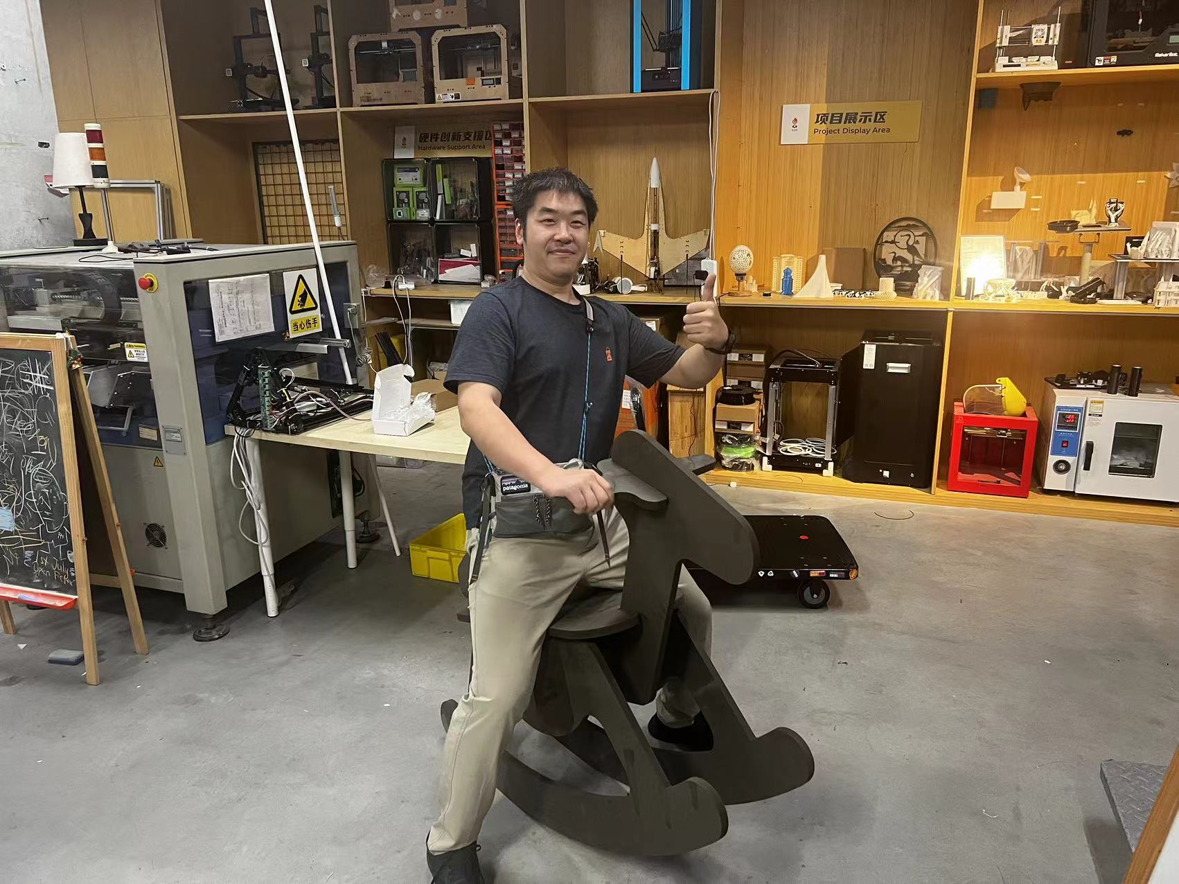
- My Hero Shot of Final Horse is Ready!
- Assigmemnt files
week07 Computer Controlled Machining
Week 7 - Overview
In Week 7 of Computer Controlled Machining, I learned several key points.
Firstly, precise design is essential at the start. Thoughtful consideration of material properties, stability, and functionality avoids problems later.
Secondly, choosing the right milling tools and parameters matters. Different materials need specific cutting speeds and depths for good results.
Close monitoring is crucial for accuracy.
Finally, careful alignment and secure connections are vital in the assembly. Even small misalignments can affect the final product.
Overall, this week enhanced my skills for large-scale manufacturing projects.
we need to complete two projects: a team assignment and an individual assignment.
do your lab's safety training
test runout, alignment, fixturing, speeds, feeds, materials,and toolpaths for your machine
Link to our group page: Week7 Group Assignment
1.make (design+mill+assemble) something big (~meter-scale)
2.extra credit: don't use fasteners or glue
3.extra credit: include curved surfaces
Reference Links
Week7 Computer-Controlled Machining Guide for my Fab Academy Journey.Version control & GitLab.
What I learned from Group Assigmemnt
Safety Training
Safety training this week is crucial as the CNC machine is very dangerous. Training will cover emergency procedures, machine safety, and operational protocols including runout, alignment, fixturing, speeds, feeds, materials, and toolpaths.
Emergency Procedures:
- Train operators on emergency stop and its usage.
- Know first aid for common injuries.
- Review fire evacuation routes often.
Machine Safety:
- Understand machine controls.
- Don't bypass safety devices.
- Ensure machine grounding.
Machine Setup
Test Runout and Alignment:
- Check spindle or cutting head with a dial indicator.
- Ensure smooth axis movement.
- Confirm tool perpendicularity.
Fixturing and Workholding:
- Use proper clamps or fixtures.
- Support the workpiece well.
Material Preparation:
- Clean aluminum plates.
- Remove burrs or sharp edges.
Operational Procedures
Speeds and Feeds:
- Set speeds and feeds based on Wooden Board type and thickness. Use guidelines or software.
Toolpaths:
- Design toolpaths to reduce wear and heat.
- Use climb milling for a better finish.
- Check paths in simulation software.
Coolant and Lubrication:
- Use proper coolant or lubricant.
- Maintain coolant levels.
Machine Maintenance:
- Clean and lubricate moving parts.
- Inspect and replace tools as needed.
- Follow scheduled maintenance checks.
My personal assignment
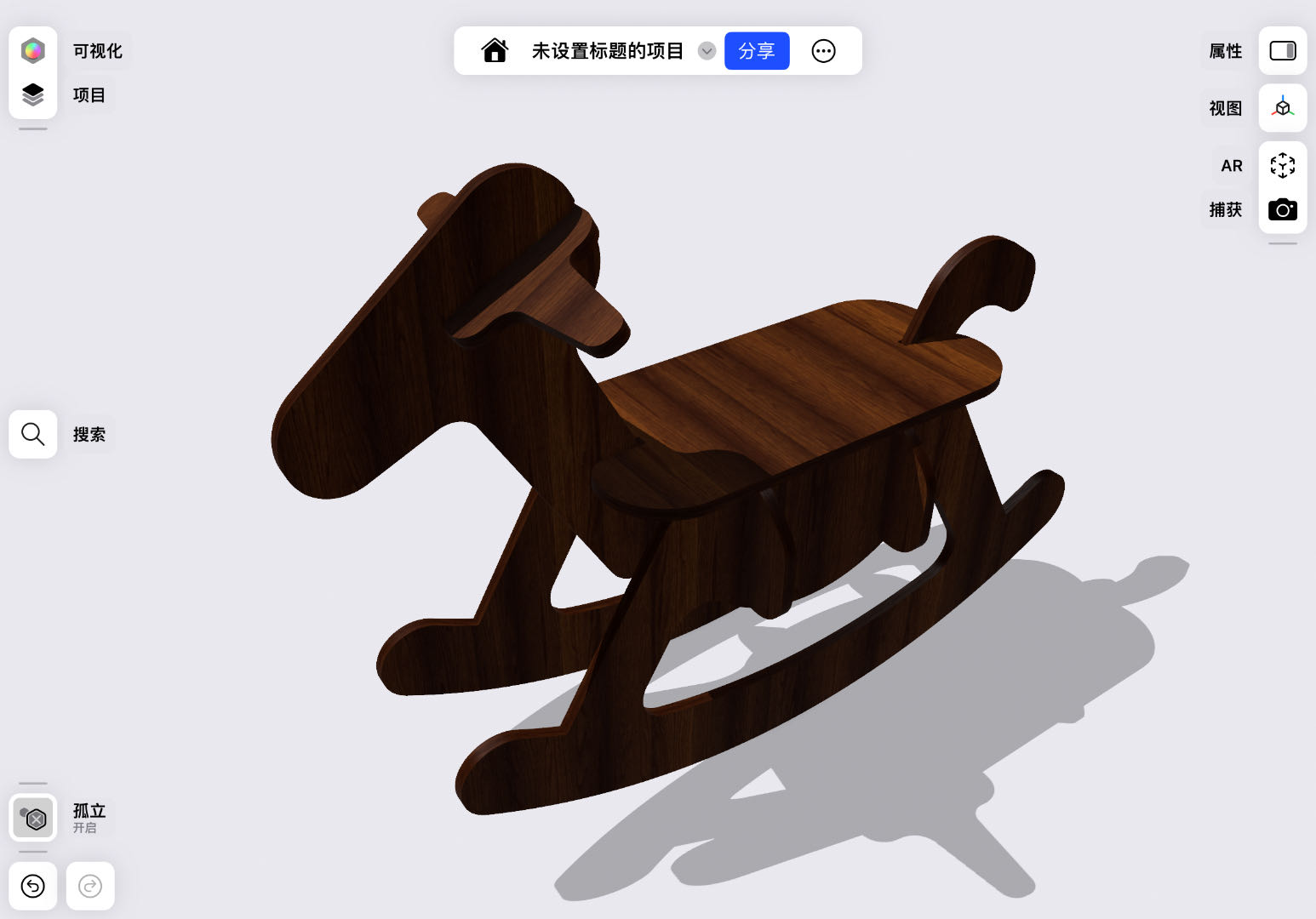
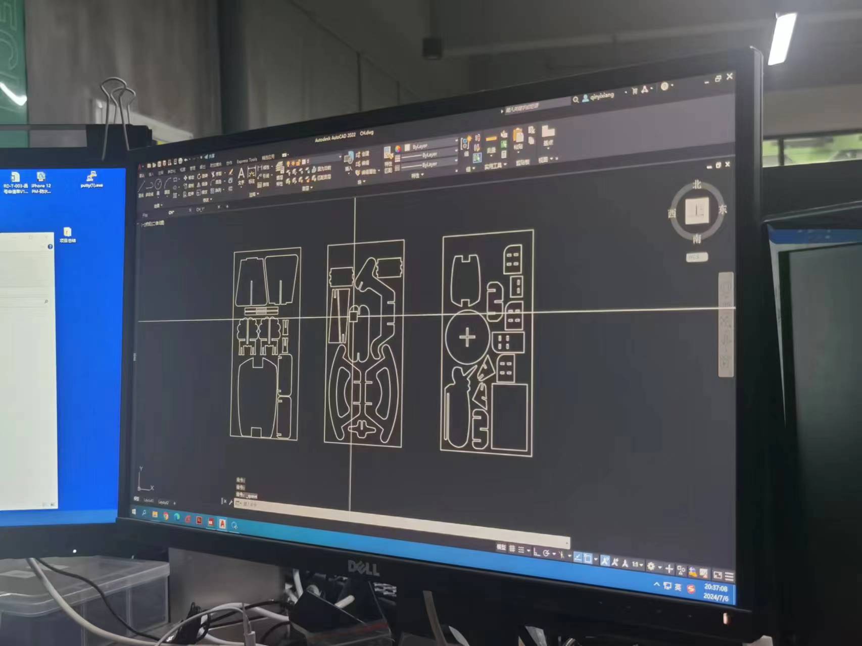
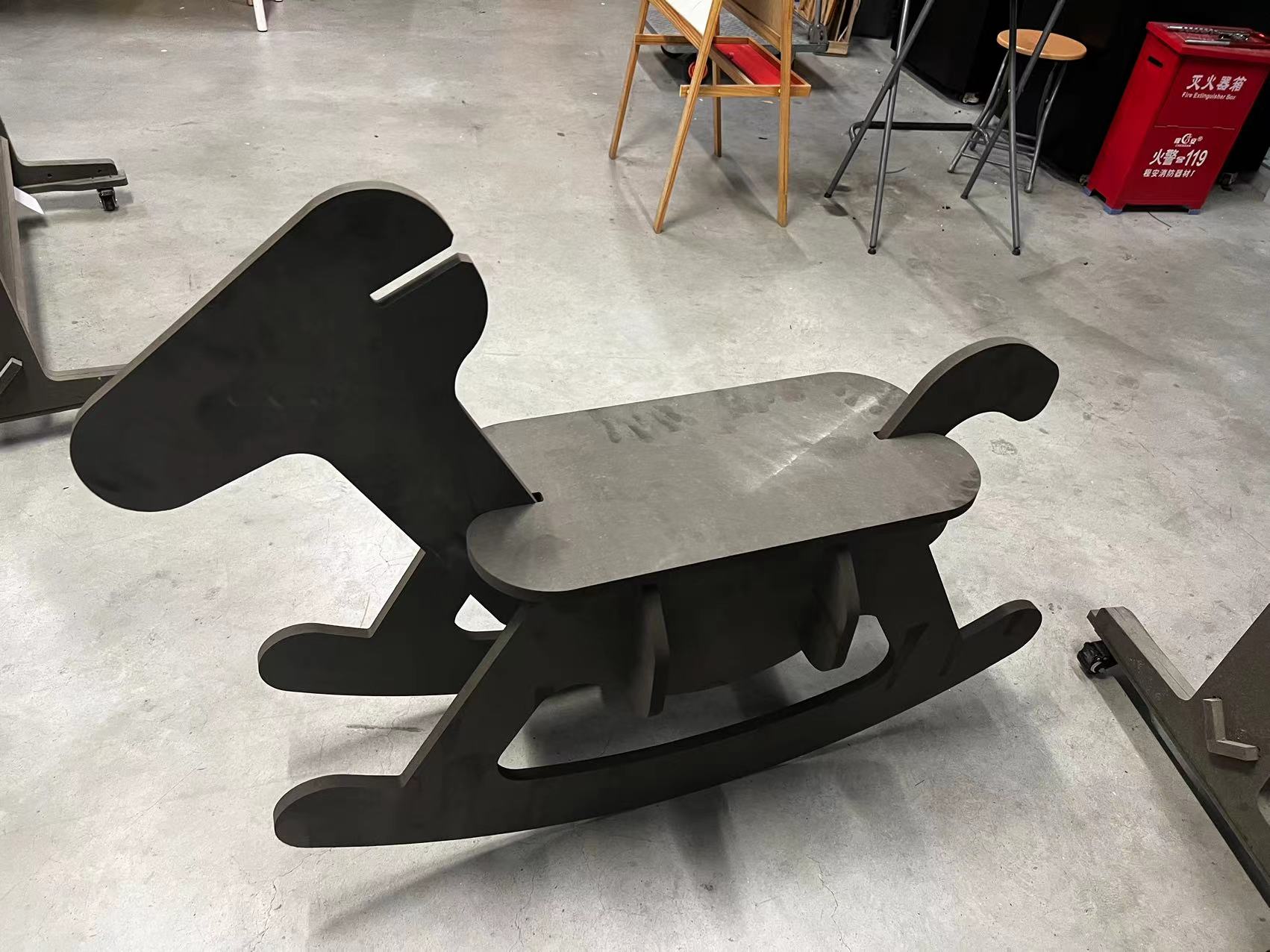
1.The wood horse design.
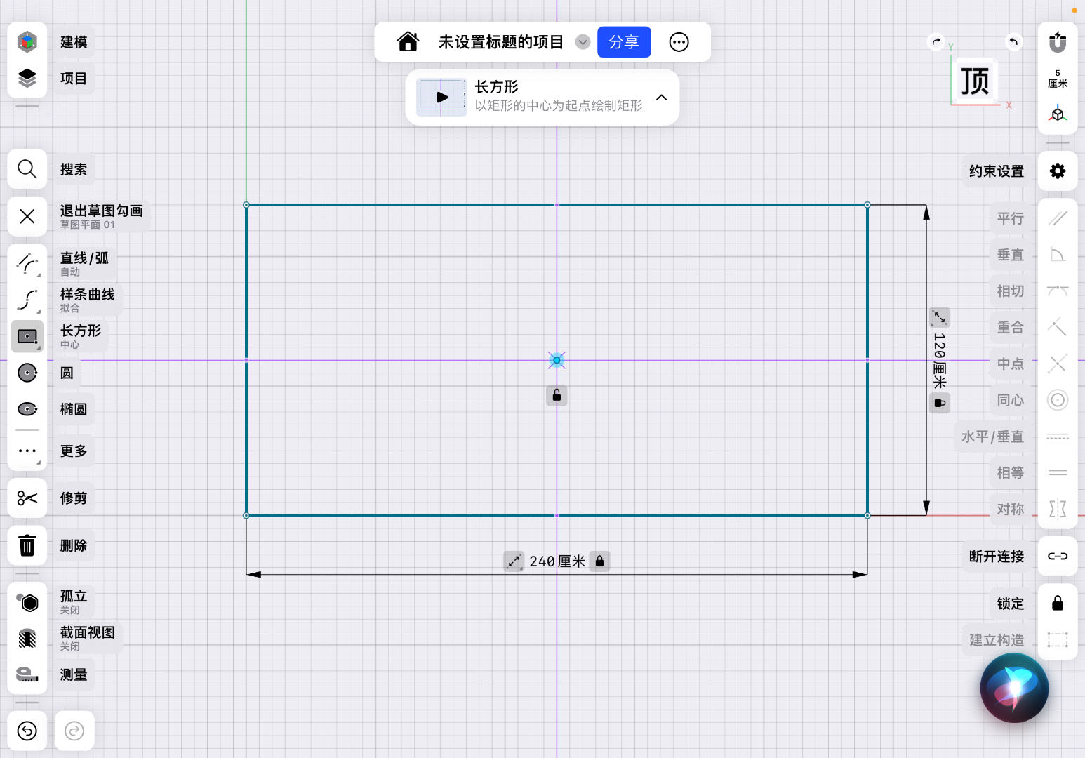
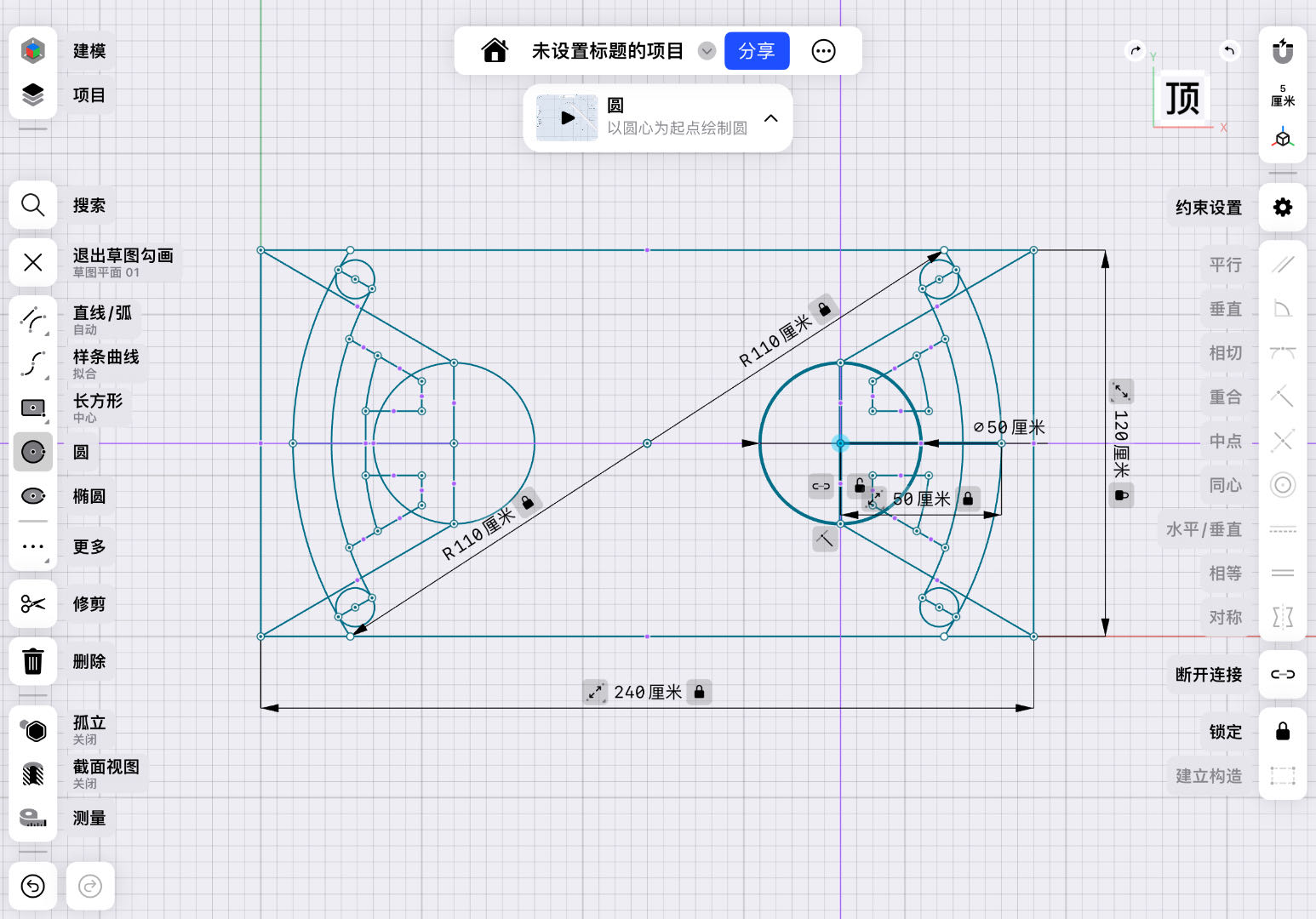
In this chapter, my initial design intention was to utilize the existing boards available at Chaihuo Maker Space for processing and design. I selected high-density fiberboard (HDF), and after measuring, its actual thickness was about 18 millimeters.
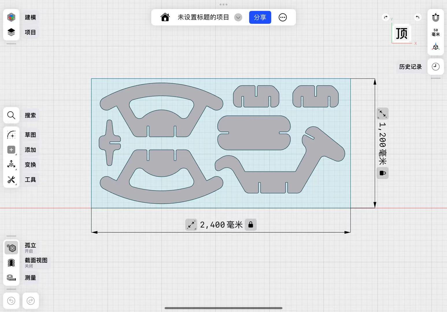
I designed this rocking horse with the precision of CNC machining in mind, allowing it to be easily assembled into a three-dimensional structure. Of course, the standard factory dimensions for mainstream boards are 2440×1220 millimeters. I arranged all the parts to be processed on a single board as much as possible, which helps reduce the waste of materials.
Machine Cutting
Preparation before Machine Cutting
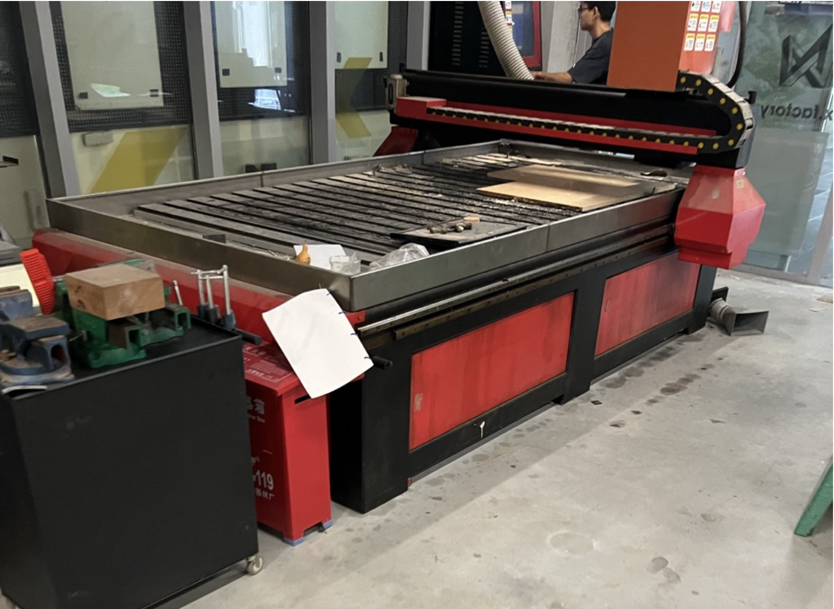
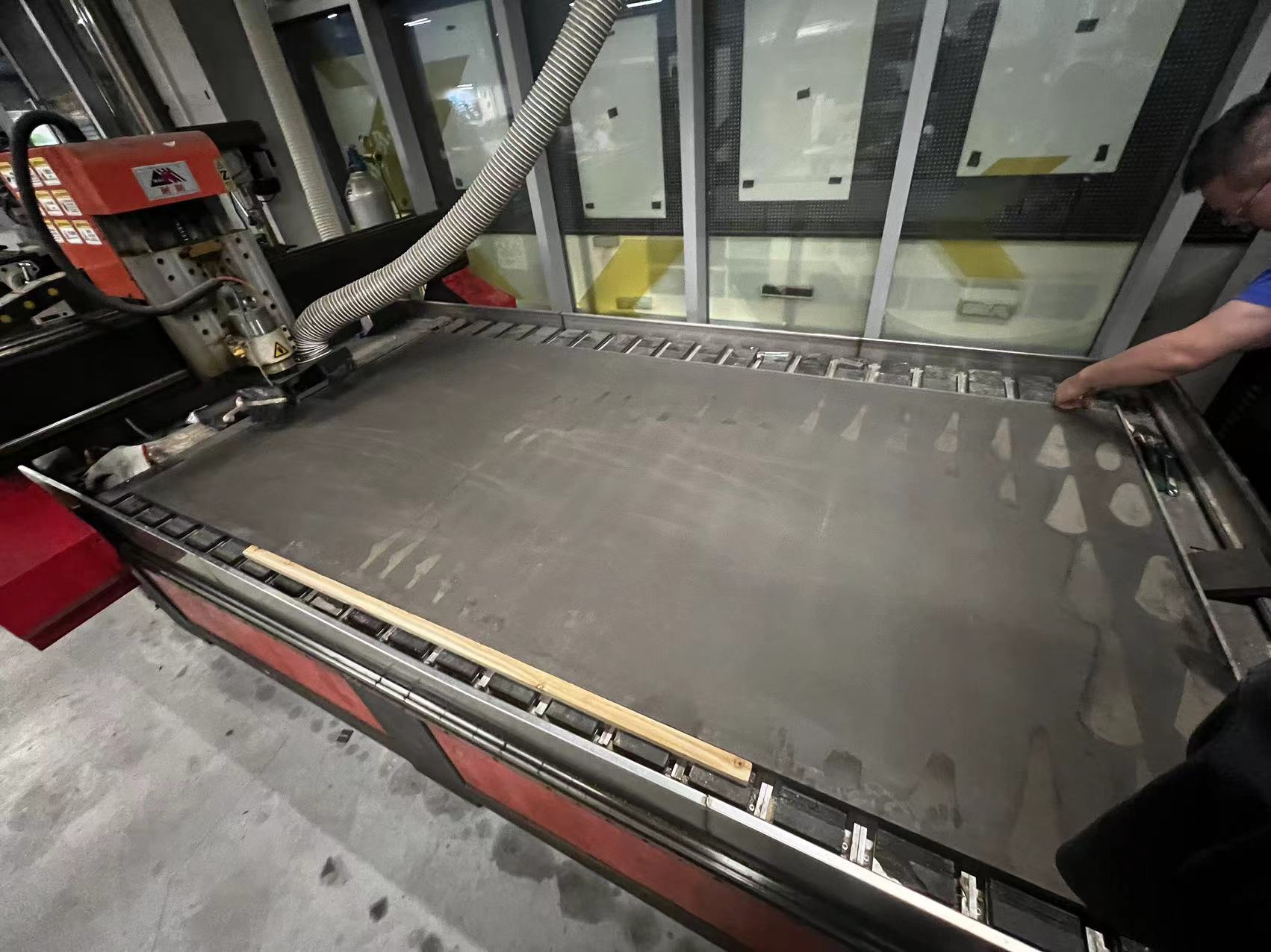
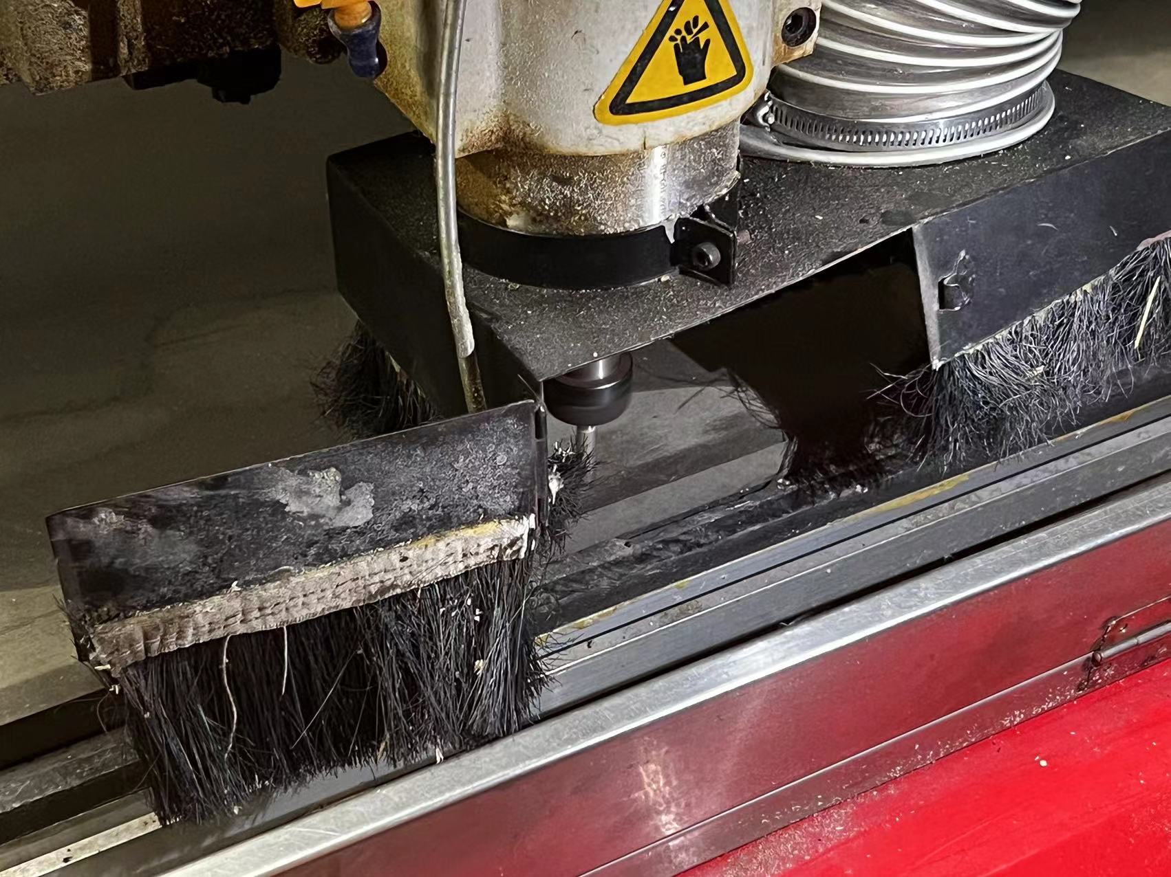
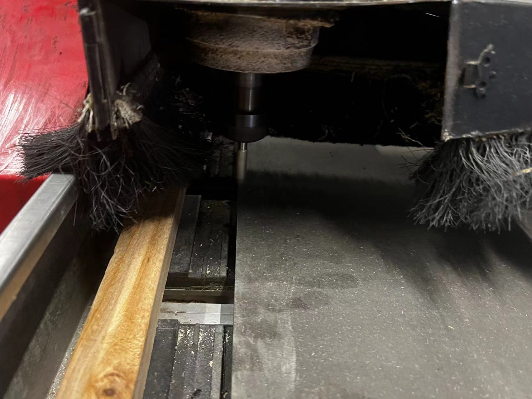
Our CNC Machine
Prepare the G-code
All of our teams exported our step files together and combined our furnitures on three boards.
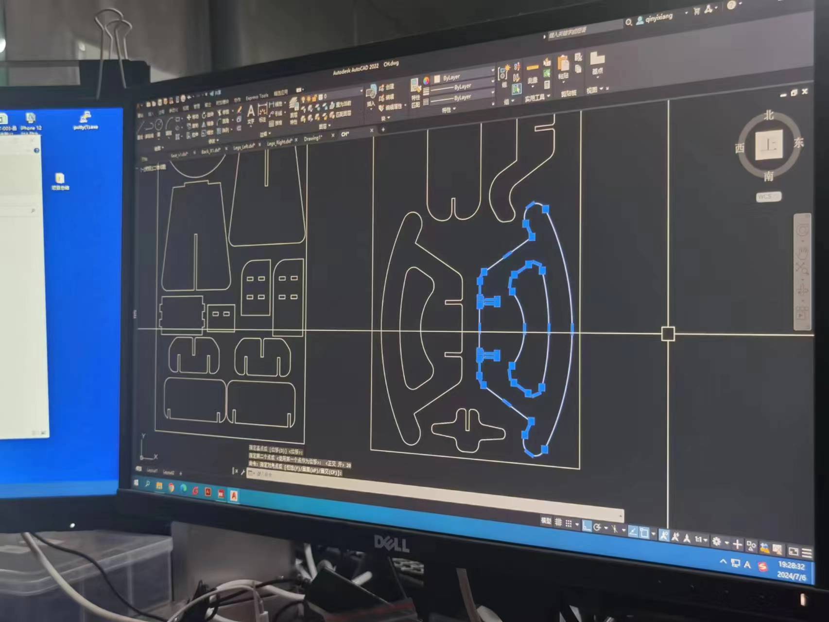
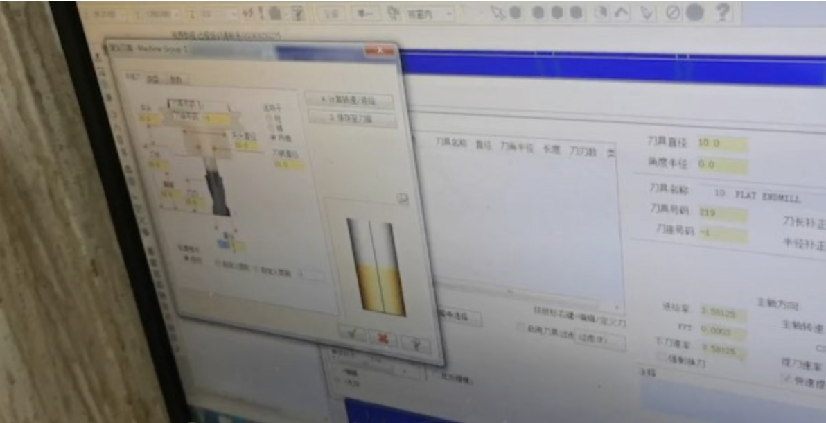
Generate the toolPath.
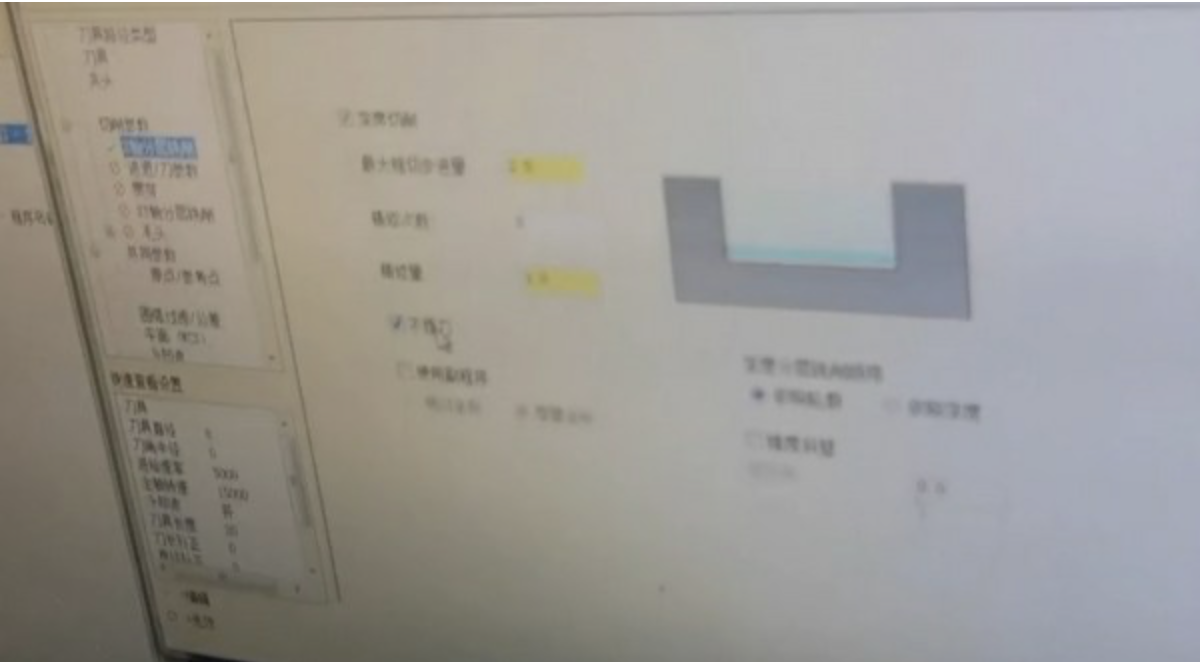
Then create the tool, an 8mm diameter tool. Set the tool parameters as follows: rotational speed 15000 mm/min, feed rate 5000 mm/min, plunge rate 500 mm/min.
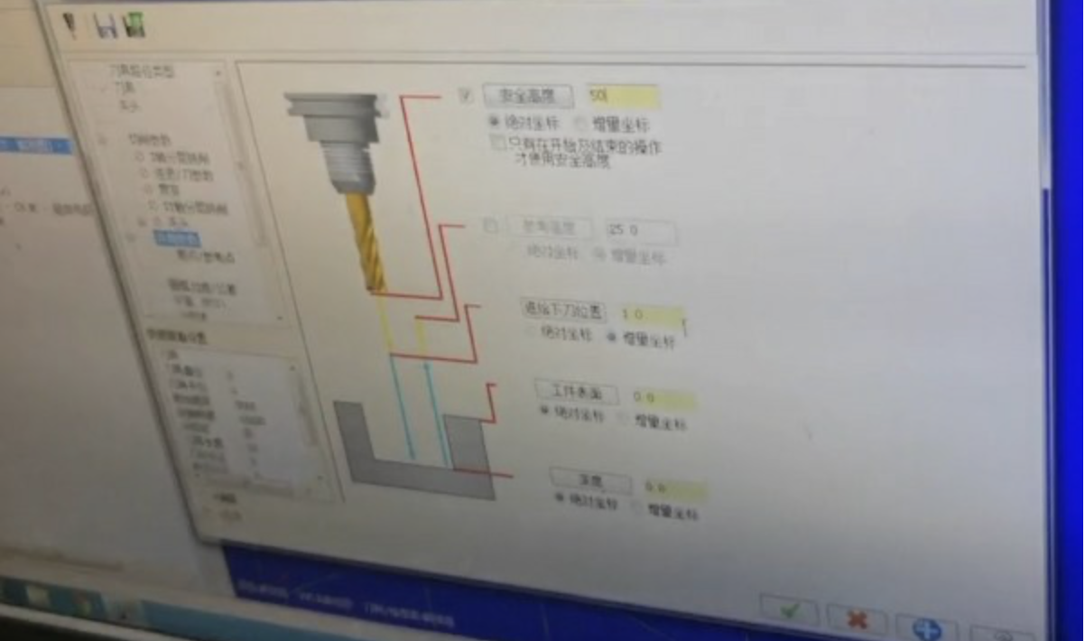
Set the safe height, 50mm - That is, after cutting, raise the Z-axis to 50mm. Similarly, the thickness of the board is set here, set to 18mm
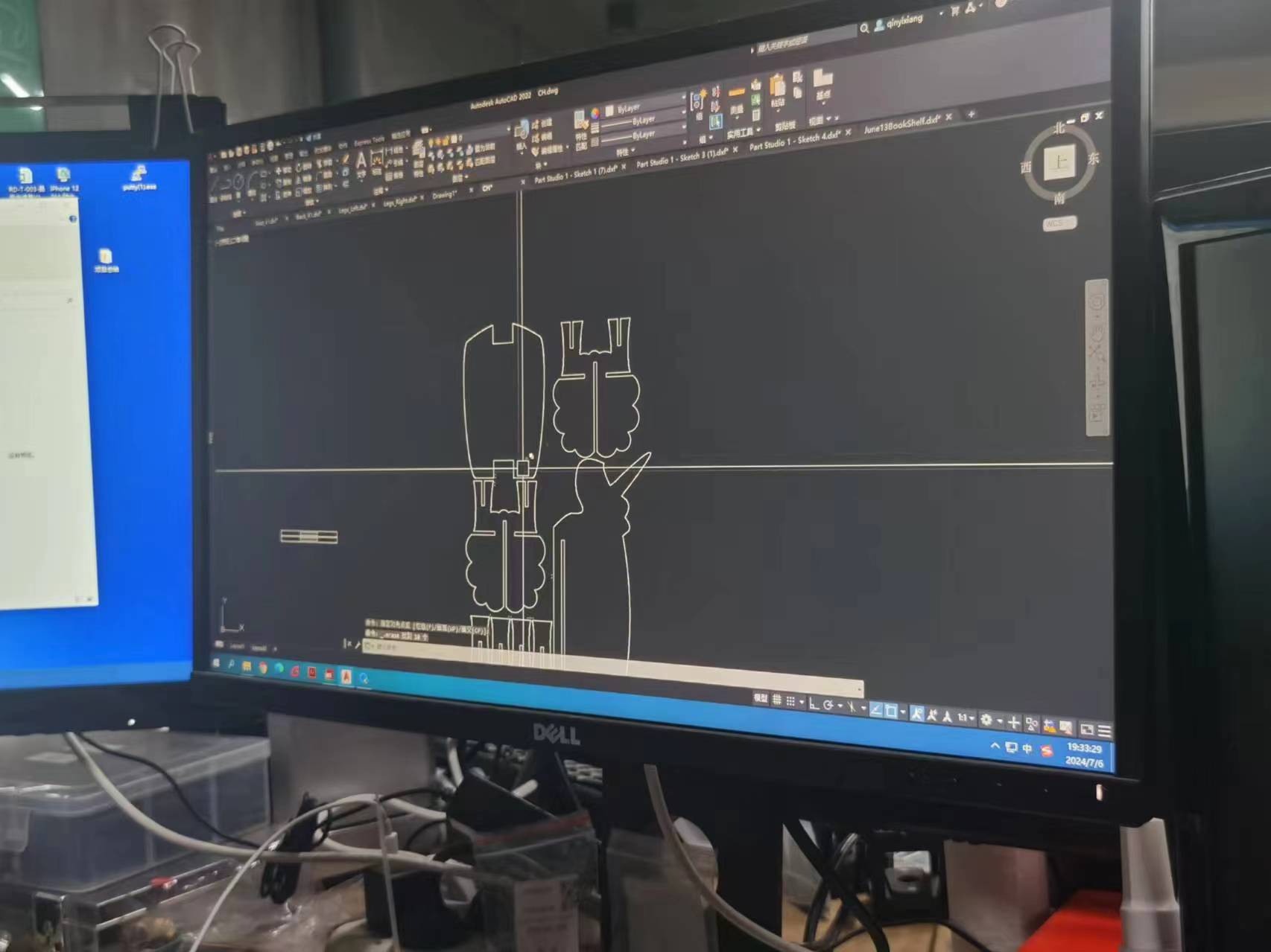
Press "R" to view the tool path. If there's an incorrect tool direction, change its series direction.

Then keep simulating the path until all the lines are in correct position as below:>
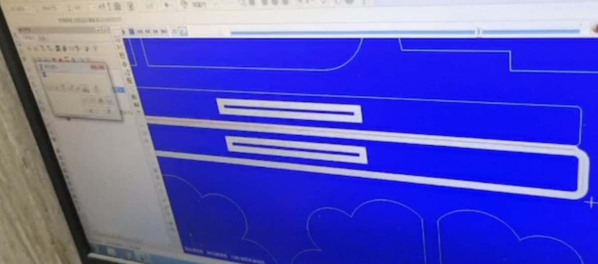
Setting the times of milling as 2.5.
Big CNC Cutting
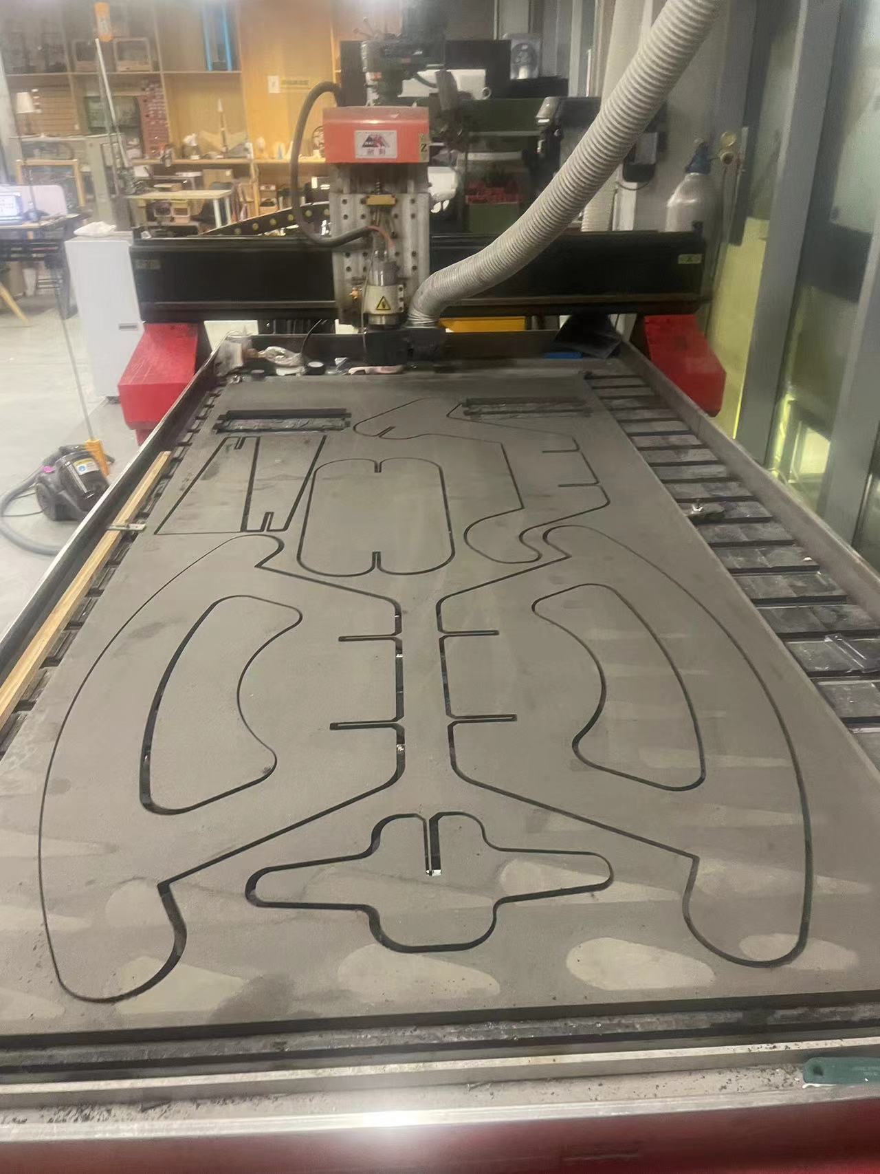
Prepare the board
Fix the board on the machine tightly, it needs to be fixed very tight otherwise the board may shift positions.
Adjust the X and Y orgin
Set all the XYZ origins
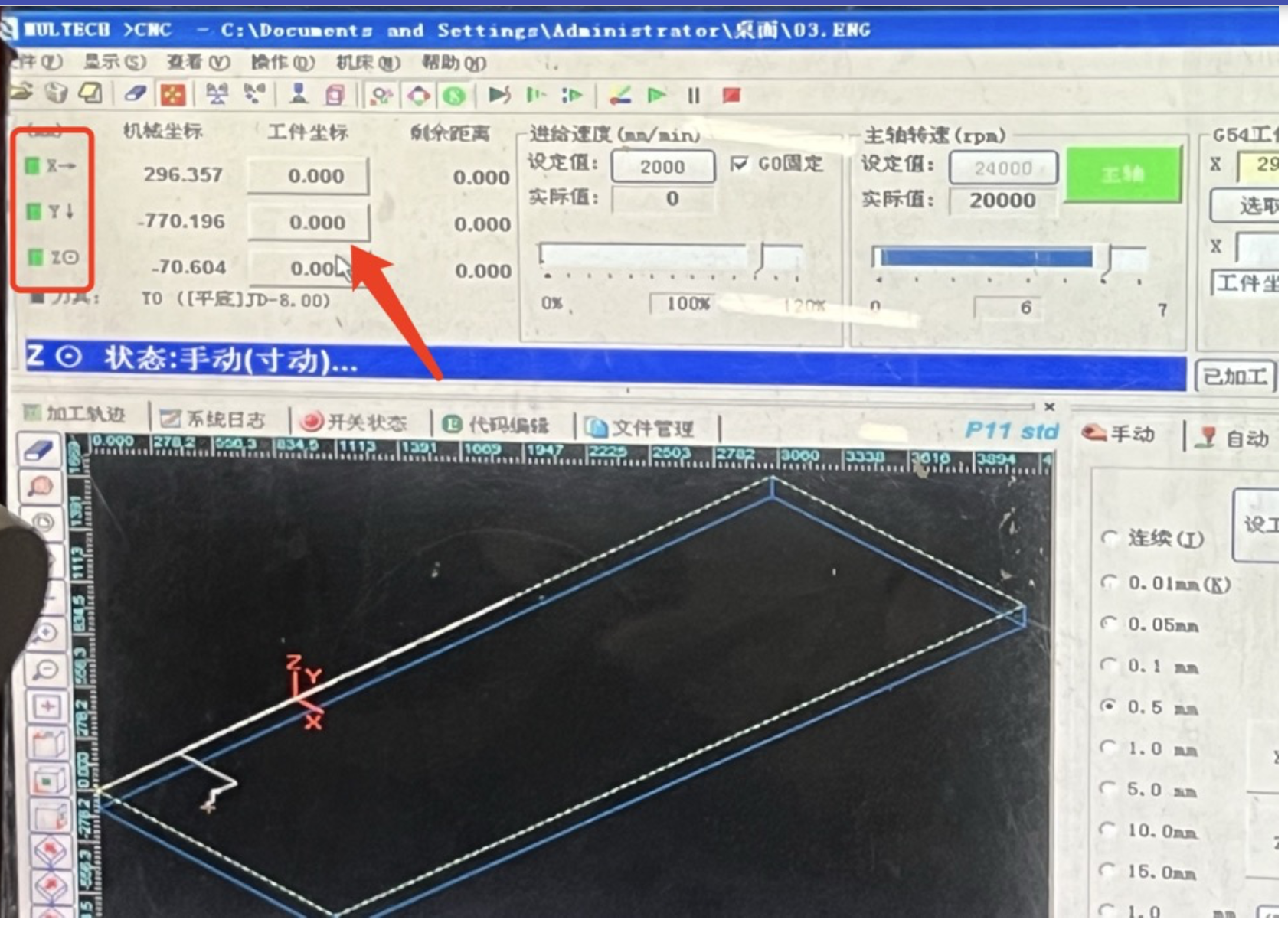
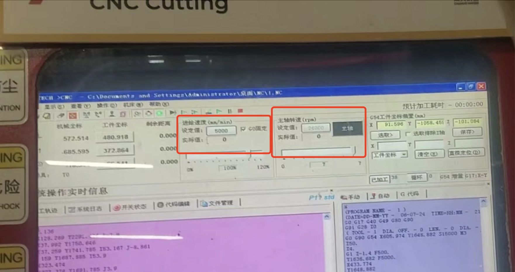
Based on the board chosen , the feed rate is set as 5000 mm/min and the spindle speed as 24000 rpm
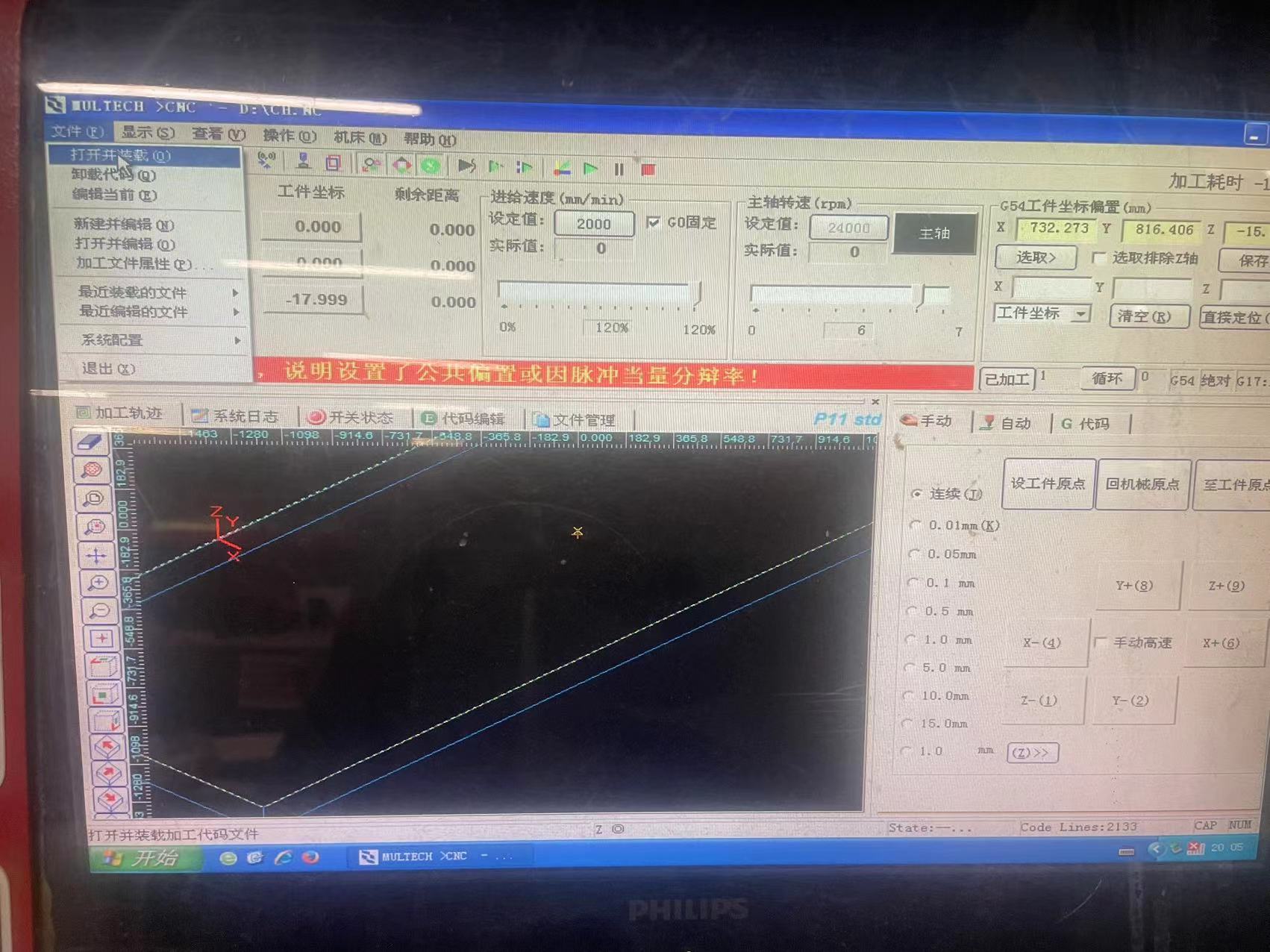
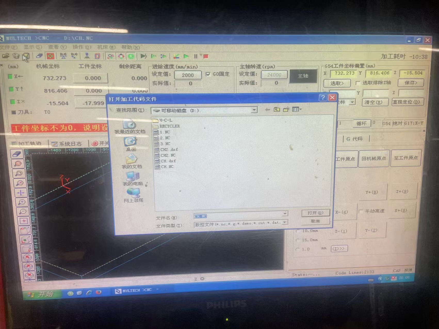
Load the Gcode file
Press F8 to make the simulation path
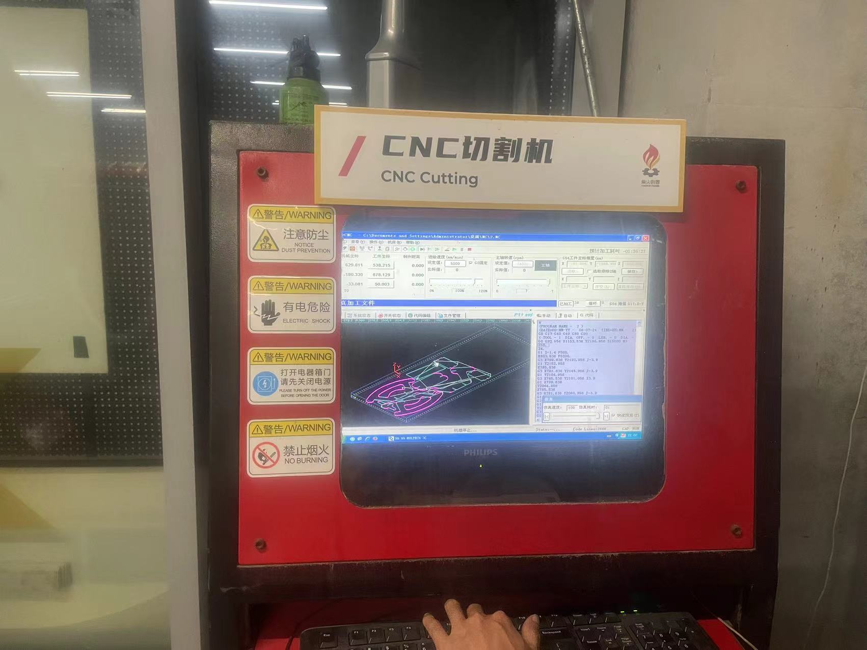
Press F9 to cut!
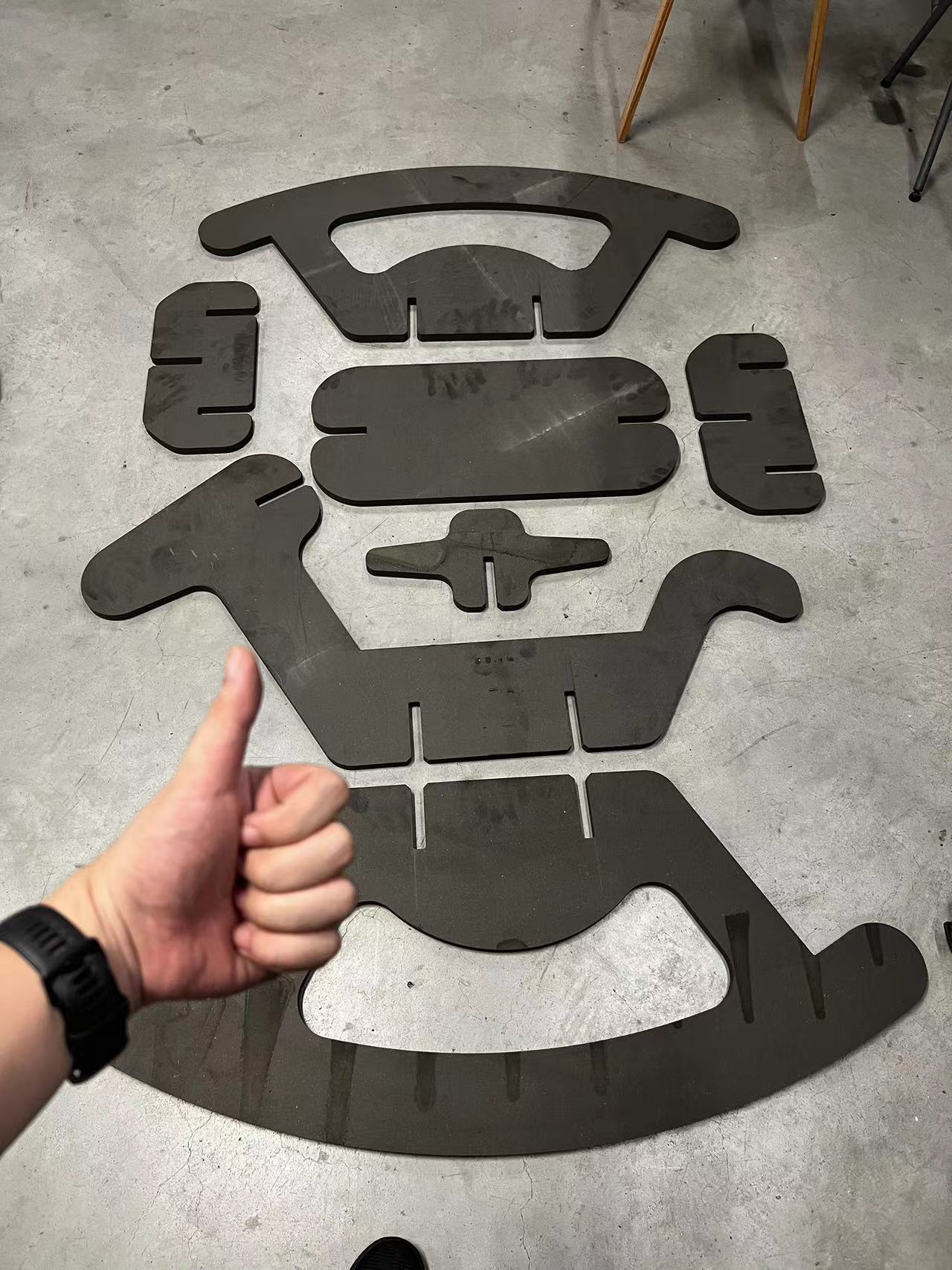
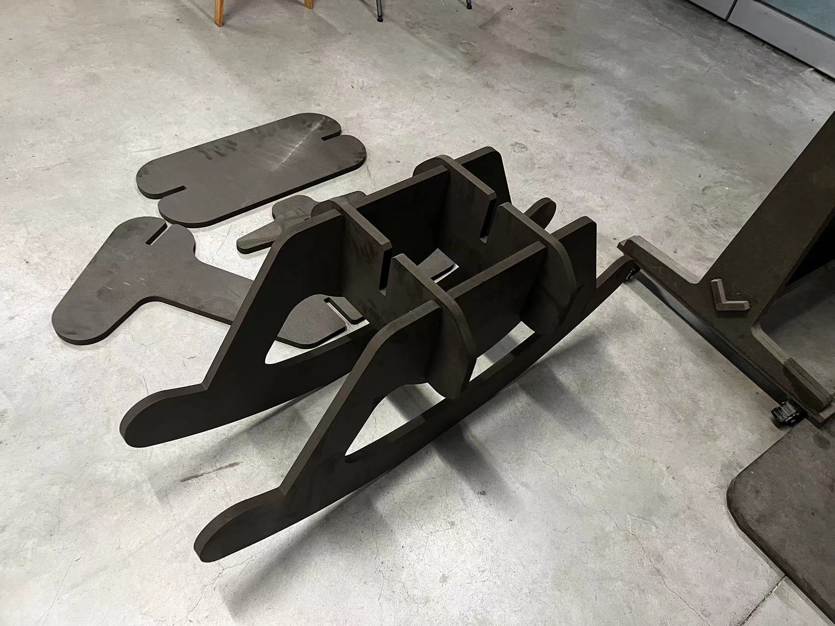
Our first board and all my components are on this board!
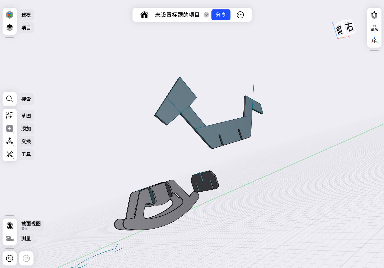
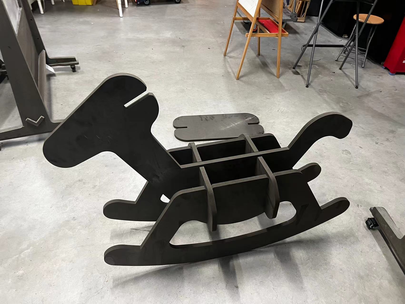
Assemble
Assemble all my parts from the bottom to top.
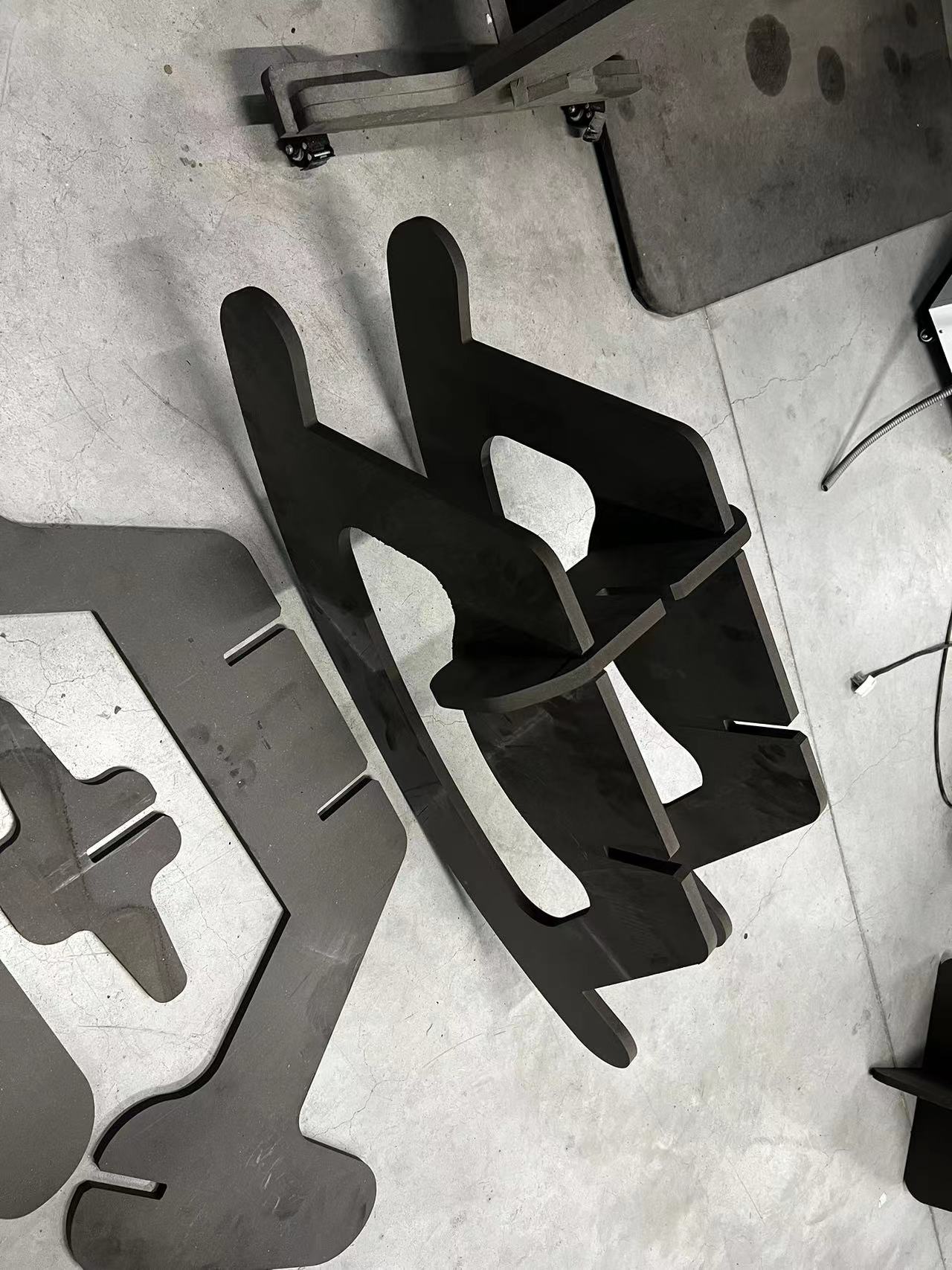
My Hero Shot of Final Horse is Ready!
Assigmemnt files
Week 7 Computer-Controlled Machining Assignment FilesLet's Jump to the Top !!!