10. Machines
This week we worked in groups to design machines that includes mechanism+actuation+automation+application. That basically means make a machine that moves stuff (which can include itself) using motors. My group did a pottery wheel. For the past few months I've been going to a pottery class and have become in some sense a journeyman potter. I constantly feel though, if i could get more wheel time I could become a zen grandmaster. Buying my own was always an option but given this class I decided why not try to build one from scratch? Below is the documentation for the project with the group.
- Group assignment here
Contents of the wheel
We began by looking at existing pottery wheels and how exactly they operate. There are a few key random notes that go into a pottery wheel.
- The motor needs to be STRONG- most hobby pottery wheels are between 1/4 and 1/2 horsepower.
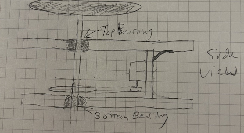
- The shaft that spins the wheel that rotates on the z-axis (let's say) needs to wobble as little as possible to minimize movement of the wheel itself while working.
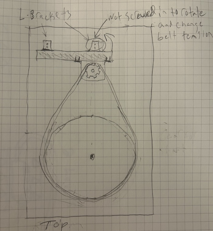
- There's usually a simple gear system trading off the motor's speed for an increase in torque- this will allow the wheel to spin when there is the weight of the clay on the wheel + the pressure of the potter's hands.
- A pulley belt is usually used to turn the gear attached to the shaft from the gears directly attached to the motor
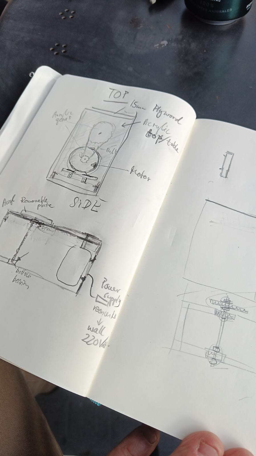
The High Level Sketches/Inspiration
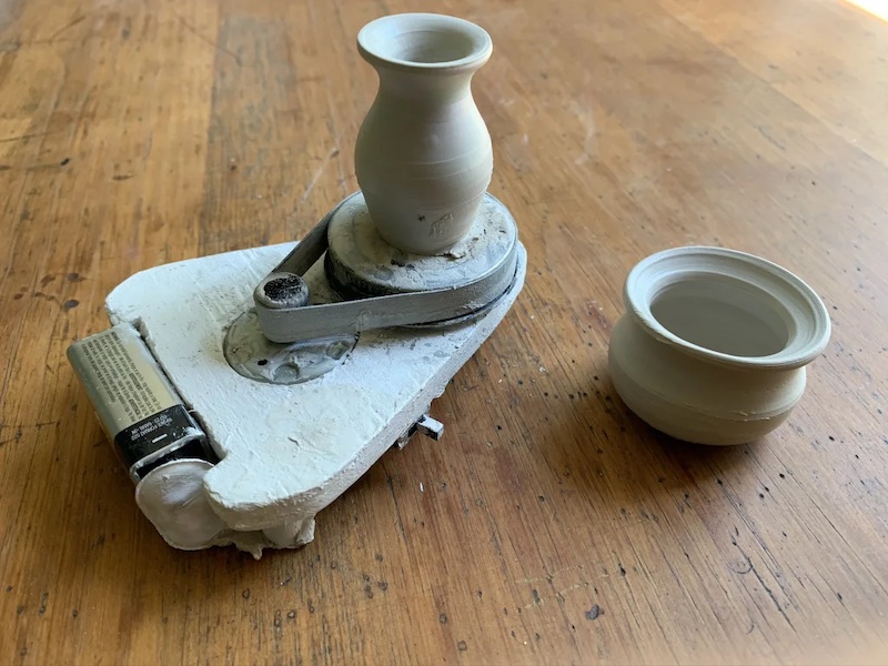
We really liked this pocket pottery wheel. It used a rubberband as the belt!
Trying different parts
We were initially given a pulley belt that we actually used for the remainder of the project.
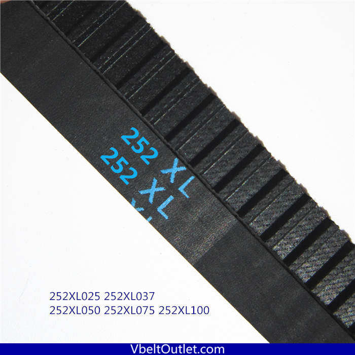
We were also given a first motor to start working with. Once we got the motor and the pulley we began modeling the gears based on the pitch of the teeth of the pulley belt's we had been given, the diameter of the shaft of the motor, and the length of the belt.
As far as modeling the belt distance, it was a bit more mathy than originally expected so for the original gear modeling we just approximated with some margin for error and decided on some reasonable gear combinations. The goal was to maximize the gear ratio with the band length we had been given. Initially we 3D printed our gears. We tried printing on both the resin printer (because of its precision with small parts) and the prusa just in case. The resin print failed and so by default we began testing with the gears printed from the Prusa.
The gears fit well on the shaft of the motor. We then held the belt taut and manually turned the gear on the motor. The fit of the teeth seemed to work well. Great signs. This wasn't exactly a complete test, however. We still had to cut the gear that would be attached to the shaft that turned the pottery wheel.
After doing some initial cuts for our gears and the threaded rod we had arbitrarily chosen as our wheel shaft, we found a good fit and used nuts and washers to help fasten the gear to the shaft. We came up with a simple test to see things in motion and adjust belt tension.
It was an encouraging first sign. But after further testing and messing with tensions, we realized the small motor we were using didn't have the torque we were going to need. We swapped it out for a bigger motor found in the lab. It was definitely a whole lot more beefy, great.
But how do we run a more complete test? How do we make sure the shaft will be stable? We begin with leftover wood and build a complete monstrosity. We used a gear ratio of 4.5 to 1 (70 teeth to 20).
Well...it spun but gosh darn was wobbly. Maybe a case of horrible vertigo could balance out the wobble of that thing. We noticed a few issues to fix in our next version:
- The board the motor is attached to show be tall enough to be attached to the top and the bottom pieces of wood of the structure. This would help with keeping the motor's shaft's gear in alignment with the larger gear. It also would help with some of the vibration of the motor.
- Use a shaft that fit better between the two bearings we were using.
- Shorten the length of the shaft to minimize the angular moment the wobble was adding (which was subsequently throwing off the wheel).
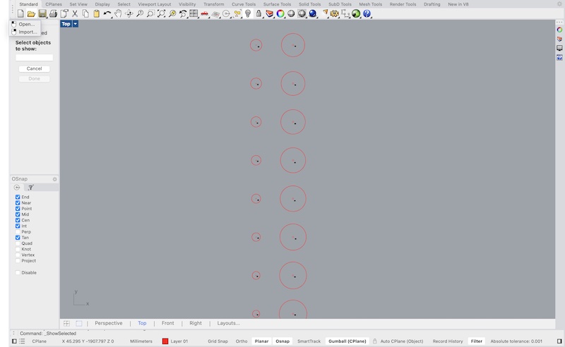
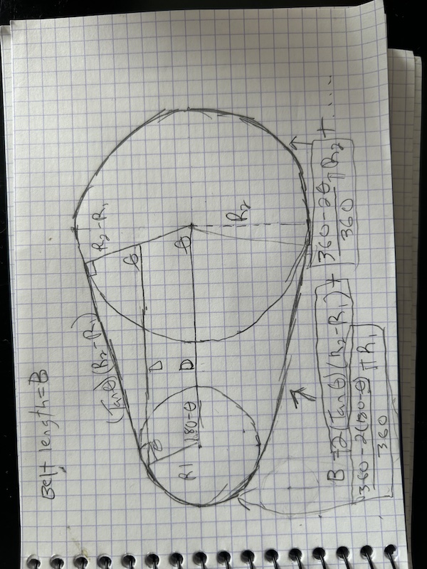
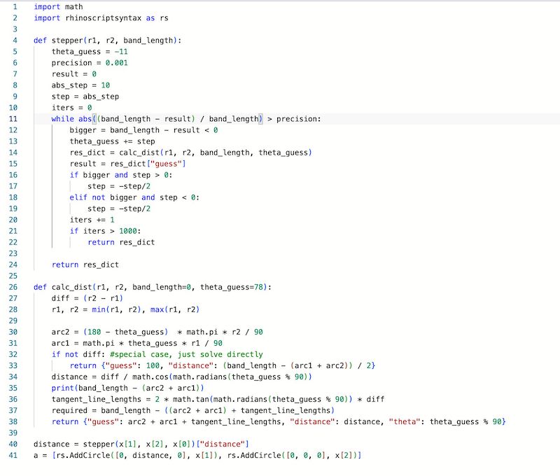
We decided to use the CNC to design the box/external structure. To do this we needed to be a bit more precise with the calculation of distance between the gears. Some basic geometry was done for this. It was a bit beyond me to solve it analytically (still unclear how that'd be done) and I knew once I had the equation I could write a simple script to calculate it to a certain precision so I saved myself some effort and did that.
Next we had to make a box which we used a website to do because it does all of the teeth and notches for you. I added the dogbones after to make the PERFECT FIT. SNUG
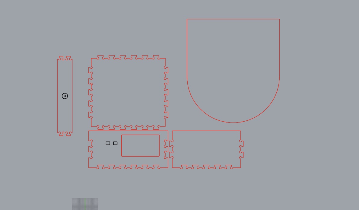
We did some test cuts to get the correct size for the bearing pockets. We didn't want those sliding or moving in the box, they were only there to support the rotation of the shaft. After some failed cuts we finally did get a first version done.
Wow, marked improvement but still too wobbly for a real one like me to actually throw clay on. And the torque was also not acceptable, I could stop the wheel with my hand. We decided to tackle the remaining wobble problem with 4 more bearings below the wheel to keep it even.
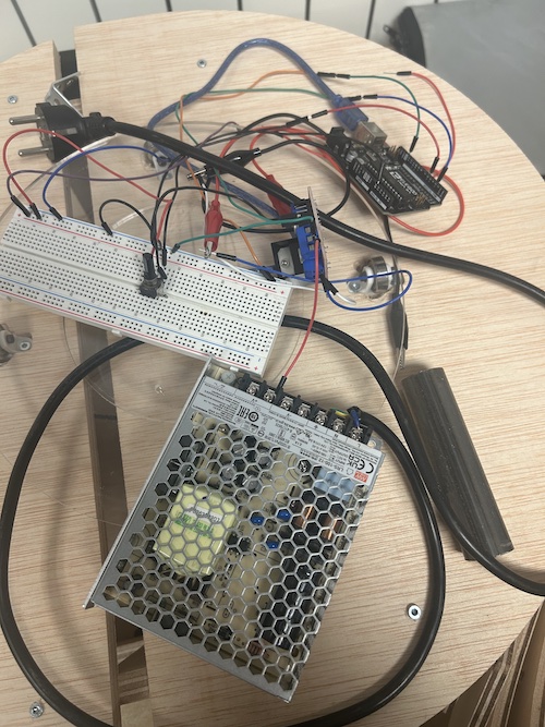
It really did work! but it caused even more friction which make the torque problem even worse. We didn't have a ton of time left in the week, however, and we really had to solve the electronics portion of the task. We thought it was going to be simple but after several iterations we finally got somethign working. We ended up controlling an H-bridge (which was powered by a 12 volt AC/DC converter) from an arduino and used a potentiometer to to control the power being supplied to the motor (which in turn made it spin faster or slower). Also with the H-Bridge we would be able to switch directions of the wheel as well easily.
Model files, Arduino code, Grasshopper code.
All files fromt his week can be found here: