9. Outputs
This week was outputs week which builds on our efforts to make a dev board in week 8. With our dev boards from last week (allegedly working) we can now unlock the power of controlling devices from it and programming what they should do. A simple example of an output is turning an LED on/off. We also saw some really cool examples pertaining to motors and many of the use cases they have in all of the machines we've used thus far (3D printing, CNC, and the PCB mills). Many of these motors have microcontrollers (called drivers) to hide away some of the complexities of controlling them. Unfortunately this week I didn't play with them much as I was continuing my knock off GameBoy idea. Without further ado, onto the week's fun.
For my output I used my screen for the gaming device which will be complemented in week 11, inputs, by the gaming buttons.
- Program/control an output from our new dev boards to a peripheral device.
- Group assignment here
Game Console Part 2 Take 5
I left off last week with a non functional PCB because of designing with the wrong chip. The next board I printed had new issues but these were of my own doing. In inkscape while preparing my traces I must've accidentally stretched them in the X direction!
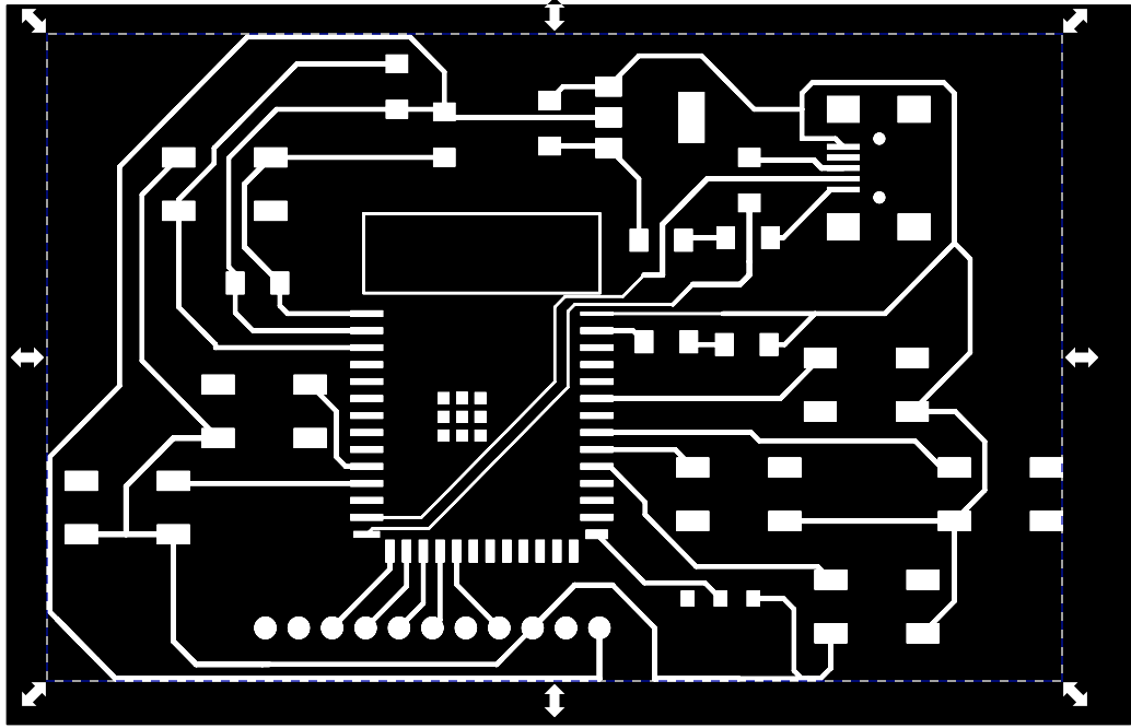
It may be unclear from the images but the slight stretch proved very problematic later. I didn't initially notice, but when I placed the esp32 on the pads it just didnt seem to fit! Unfortunately i didnt take a picture of that one but I promise you it was sad.
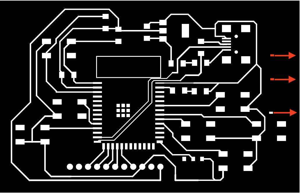
Onto the next...I printed once again, making 100% positively sure that I did not have any accidental slipups with the preparation in inkscape. Sadly though, this time around I found out I had switched around the data lines for the USB input to esp-32. My USB mini has 4 output pins
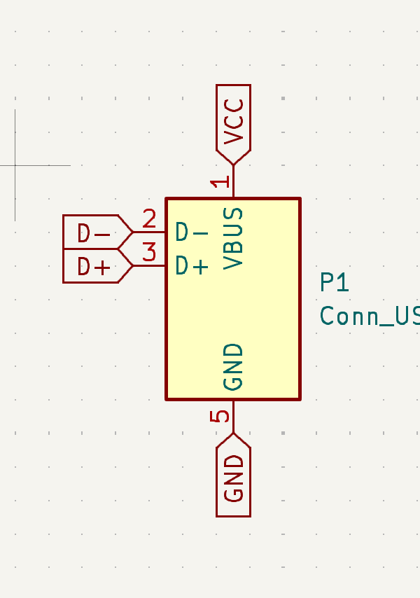
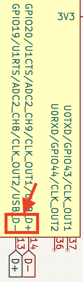
VCC and ground I had correctly configured. But after finishing soldering the board and not being able to connect to the computer I reviewed the ESP-32 datasheet and realized I had carelessly swapped the data lines
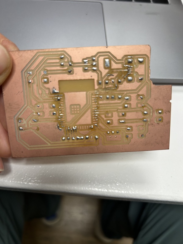
After removing all of the components I was sad. Really sad. How many more ways could I fail? After a few minutes I picked myself back up and decided I was prepared to find out. I went back to my schematic and did the traces over with the correct data lines. I carefully prepared the files for the mill once more. After about an hour I was ready to solder my new and improved, COMPLETELY CORRECT board. I got to soldering with one known flaw- The LCD screen I was going to use has 11 pins and I was only outputting on 8 pins. I had already decided to use a breadboard for that portion and if it worked I could do a reprint with the correct number of pins. I resoldered the components from my initial failed attempt.
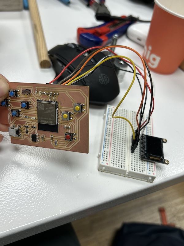
I had also confirmed it was programmable! It wasn't pretty but I finally had something working. I got started on programming my game engine. First thing to do was just get accustomed to the graphics.
This week complements input device week and the code is the same. Basically a user can press a button and it will display the button name on the tft screen (which is the output). In input week I focus on the code for the input buttons. Here I will go over the code for the screen. First I include the Arduino's TFT graphics libraries
          #include <Adafruit_GFX.h>    // Core graphics library
          #include <Adafruit_ST7735.h> // Hardware-specific library for ST7735
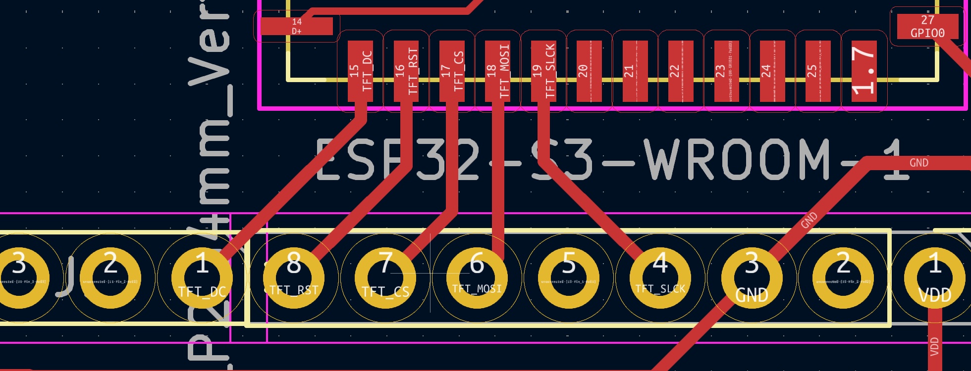
Then I set the pins for the screen's output pins
          #define TFT_CS        9
          #define TFT_RST        46 // Or set to -1 and connect to Arduino RESET pin
          #define TFT_DC         3

          #define TFT_MOSI 10  // Data out
          #define TFT_SCLK 11  // Clock out
Then an SPI object is explicitly crearted to ensure we will be using hardware SPI for faster refresh rates. This is very simple on the ESP32-S3 because you can basically use hardware SPI on any pins you choose as they are multiplexed. The graphics library classes are also created, with the SPI class being passed into the constructor.
          SPIClass *spi = new SPIClass(HSPI);
          Adafruit_ST7735 tft = Adafruit_ST7735(spi, TFT_CS, TFT_DC, TFT_RST);
          GFXcanvas16 offscreenCanvas = GFXcanvas16(160, 80);
Then the graphics and SPI libraries are initialized and started in the setup function. The frequency of the SPI is set explicitly as well, once again to ensure a high refresh rate. This is important for gaming. The screen is then made black and rotated to the correct orientation.
          spi->begin(TFT_SCLK, -1, TFT_MOSI, TFT_CS);

          tft.setSPISpeed(80000000);
          tft.initR(INITR_MINI160x80);  // Init ST7735S mini display
          tft.fillScreen(ST77XX_BLACK);
          tft.setRotation(3);
The screen I'm using is the 0.96" tft display. The pins that I use to communicate with it are
- Vin- the board can be supplied with 3-5 volts
- Gnd
- SCK- an important part of SPI communication is a shared clock to keep the child synchronized with the parent
- MOSI- This is where both the pixel data to be displayed on the screen and commands which the tft screen understands is sent.
- RST- Allows microconttoller to reset the screen.
- CS- tells the peripheral to wake up and start receiving commands
- D/C- This tells the tft screen if the serial data being sent on the MOSI pin is data (pixels) or commands
After that when a button is pressed in the loop function, the screen is repainted with the corresponding button name with the repaint function
          void repaint(String direction){
            tft.fillScreen(ST77XX_BLACK);
            tft.setTextColor(ST77XX_BLACK, ST77XX_WHITE);
            tft.setTextSize(3);
            tft.setCursor(0, 0);
            tft.print(direction);
          }
Here is the resulting video (which can also be found in inputs week).
Code files
Arduino code can be found here.