WEEK 17 / PROJECT DEVELOPMENT
INITIAL IDEAS
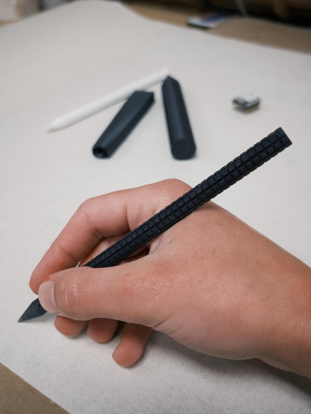
My initial ideas for the final project were mostly related to architectural design, furniture and other objects that seemed cool to design and explore, but were static and didn’t present any electronic potential. I then started thinking about interactive architectural fixtures, involving responsive lights, plugs and switches, some tools and machinery for construction and assembly processes. I also drew a beautiful faucet, but thought it would be a bad idea to work with plumbing in the lab. Whilst drawing all these things, I noticed how much I enjoyed using a pencil — and honestly just holding it for no reason — and how I wish I could sketch and annotate things anywhere without the need to bring along a tablet, a notebook or paper. I also realized for some sort of annotation I wouldn’t need to visualize lines straight away, just get them out of my brain and store them somewhere. So I thought it would be cool to create a pen I could bring anywhere, register my thoughts and later or immediately access them in the cloud.
It seems like it would be a good project to follow through since it’s not reinventing the wheel — similar digital pen technologies already exist and I can learn from them. At the same time, there is no direct equivalent, as the ones I found rely on specific types of surfaces. So it still presents novelty and challenges.
Initial challenges I thought about:
- hardware that is small enough: some digital pens are bulky for a reason. At the same time, narrow pens
already exist, but rely on advanced technology that I don’t have access to and don’t know how to operate. But
it’s ok, because it’s a prototype.
- calibrating the pen in relation to any surface: I don’t know how this would be done
- reading any surface as a plane: I don’t know how this would be done
- translating that movement into lines or text: same
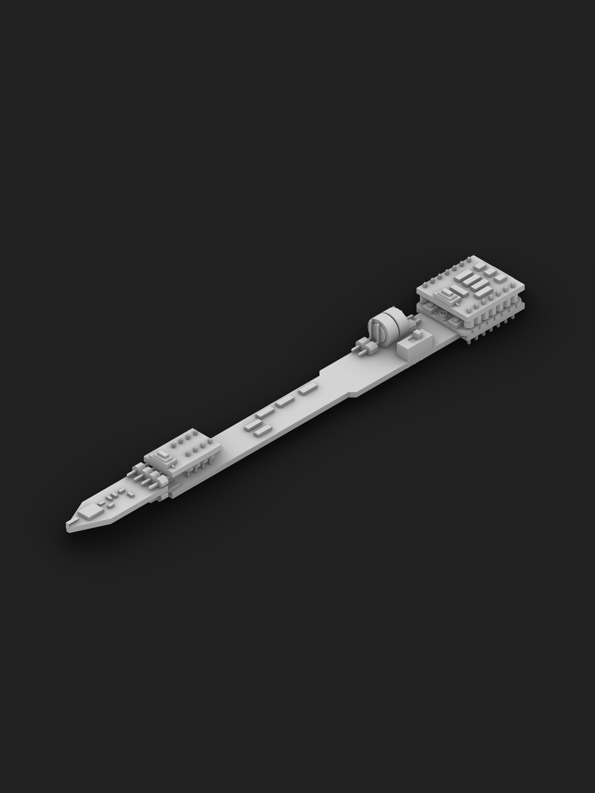
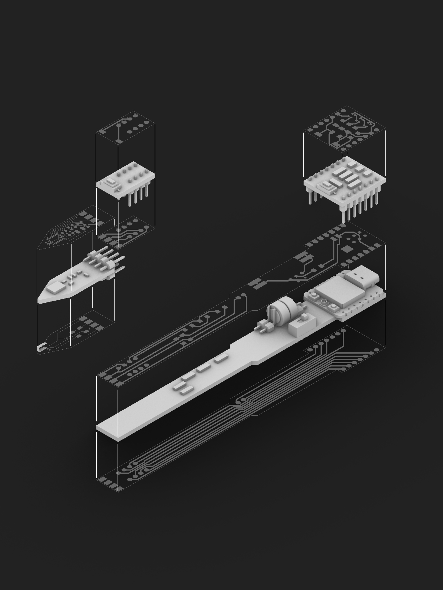
I did an initial research on the hardware size with ChatGPT: I described what I wanted and what it would do. The outcome was a potential assembly that does fit on a regular size pen — I drew to scale a traditional wood pencil and the Apple Pencil as a size reference, and compared to the parts that were suggested. As I don’t have any background in electronics, I didn’t know if ChatGPT’s suggestion would be functional, but at least it gave me an idea on what to get started on. It was nice to be able to visualize an idealized technology into separate components and understand the roles of each one of them.
I discussed this initial sketch with my local instructors and reached the conclusion that the tiny processor would probably not handle the job — but not to worry too much about size just yet, as making it a functional tool is more important and more challenging than making it small, and that once the tool is working, I can adjust and optimize the hardware and design.
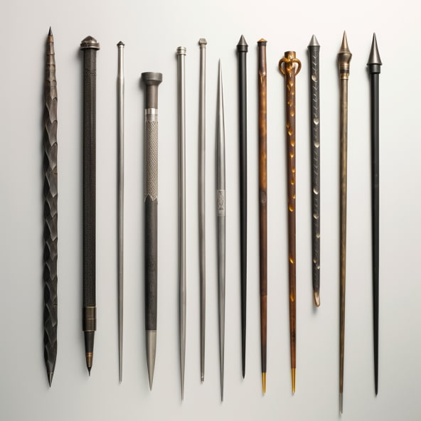
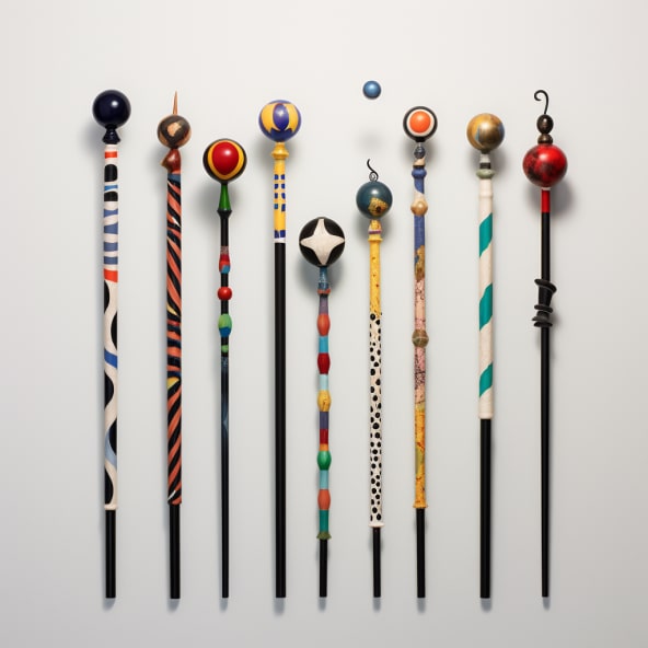
Then, I had this thought that holding a pencil is kind of like holding a wand and having powers. So as a Harry Potter fan, I thought it would be cool if everyone using this pencil thing could have their own unique wand. Then I thought I could /imagine some more unique designs. Started thinking about what artists I admire would design. One of my references for design is Dieter Rams, so I prompted Midjourney with "imagine harry potter wands designed by Dieter Rams".
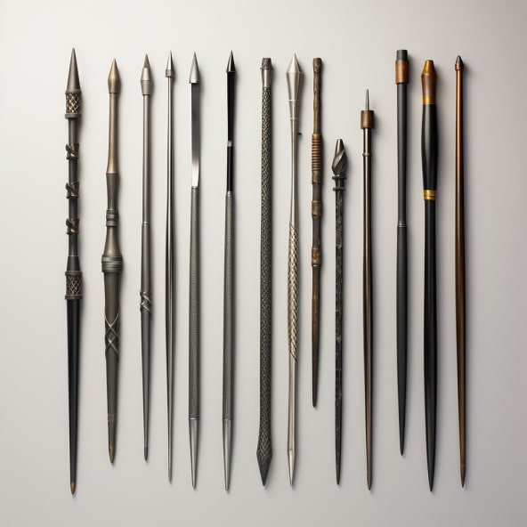
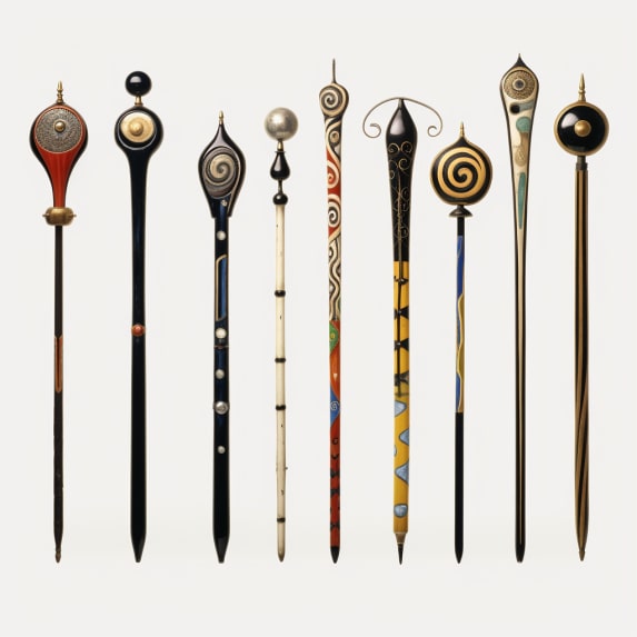
Then prompted "imagine harry potter wands designed by Joan Miró", one of my favorite artists.
PROGRESS
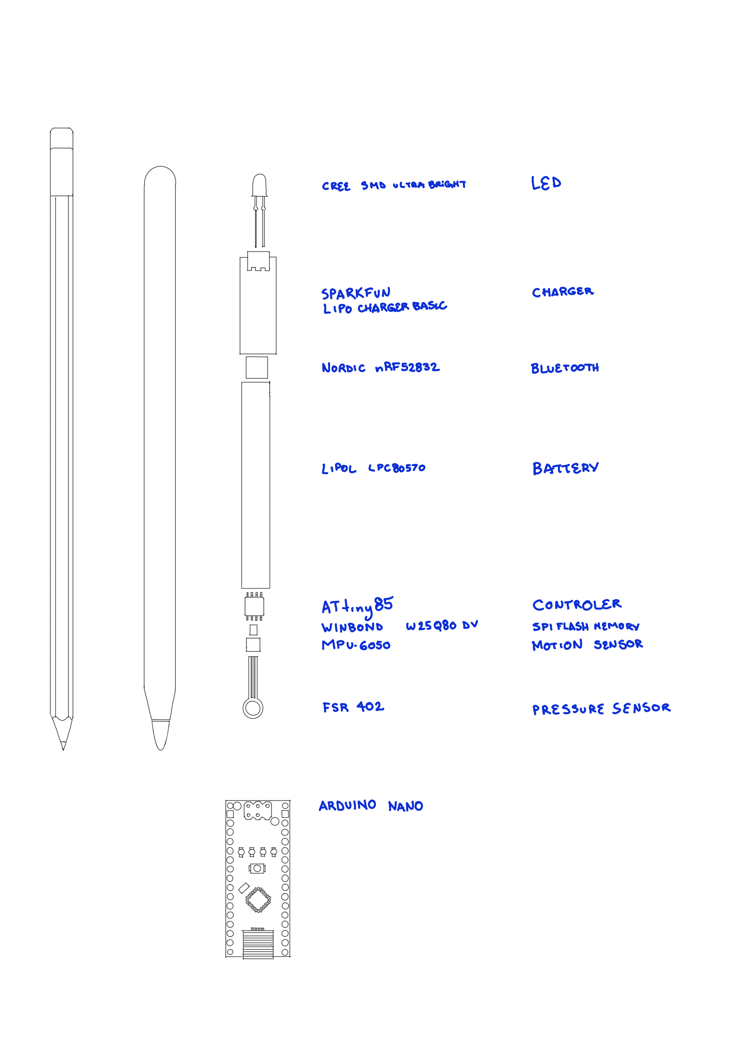
Week 1 / first research on hardware components and sizes (above).
Week 3 / sketching hollow shapes and how to open it, in order to work with components inside.
Week 5 / printing a shell to fit components size - the printing didn't work, because there were hidden supports inside the hollow part. But also found out the mechanisms would be too sophisticated to rotate at this point, when ideally I would need easy access to the internal components.
Also during this week, Michael and I decided to collaborate on the modular components and sensors of our independent projects - we are both working on the development of alternative interfaces that replace screens. We found out we could work with modular components that could be attached to different forms and work in different ways. For that reason, I started designing the tip of the pencil and the holding stick as separate parts instead of one single unit. Also started to think of shell designs that could acommodate the electronics inside for testing, but not for the final form of it.
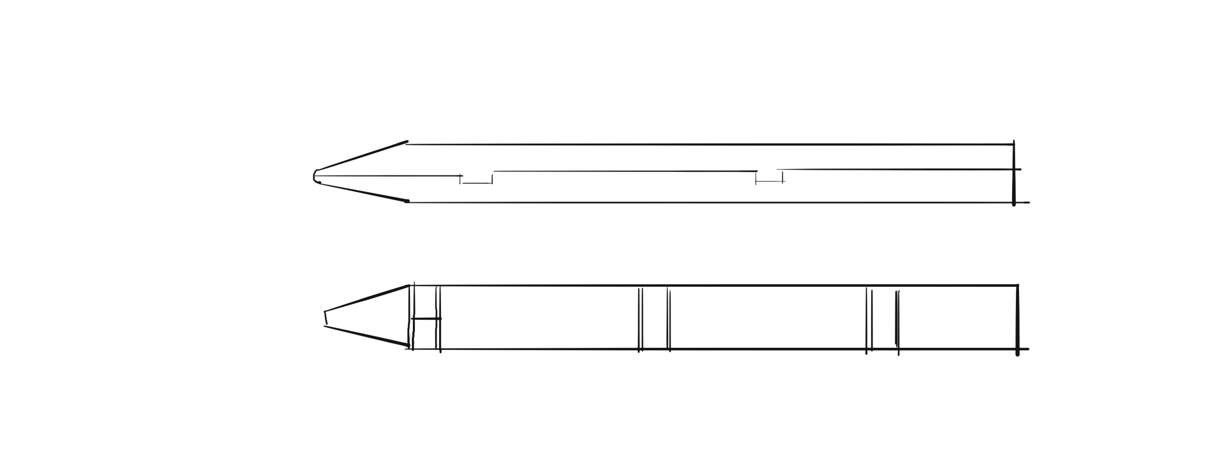
Week 6 / sketch of separate tip, holding stick and an additional component at the top. Thinking about standardising the connection parts and allow acessory or expanding function components. Also during this week, had a local review with Josep and Santi, our instructors. Sketched and talked about the priority order in terms of project development. And also got acquanted with previous works for reference.
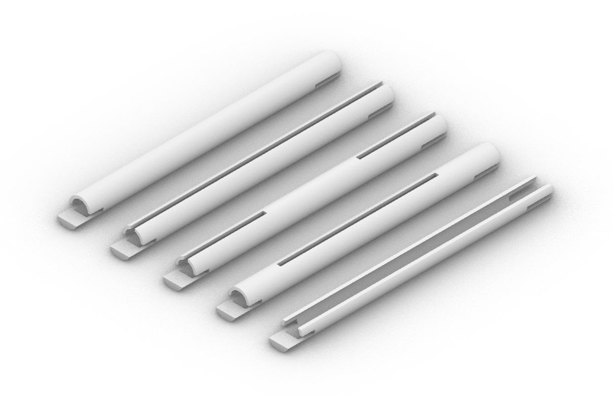
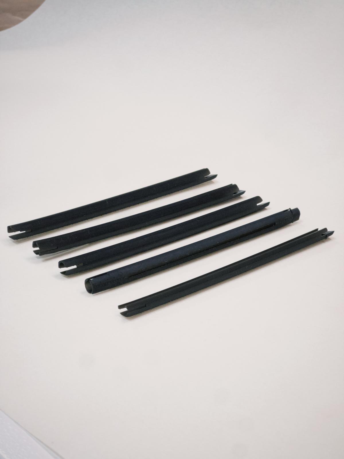
Week 7 / This is the week prior to electronics design. Since couldn't work on the final design aspects of it yet, modeled and printed a stick to hold the electronics while I work on it and test it. Sketching (above) some thoughts how to connect the gyroscope to the tip and either create a large support beyond the holding part - in order to provide flexibility when developing the electronics. What I ended up modeling and SLA printing were some stick options which I could simply fit the PCBs on the edges.
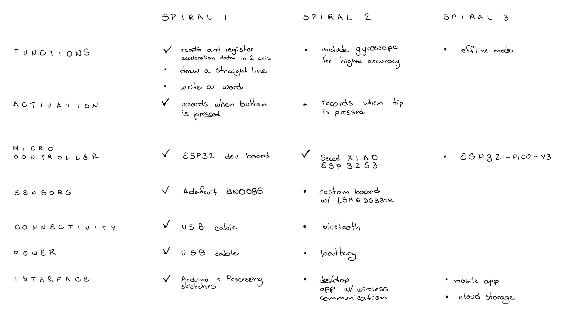
Week 7 / Started thinking of the spirals, new features and upgrading versions. The image above is a start, I'm updating as I go.
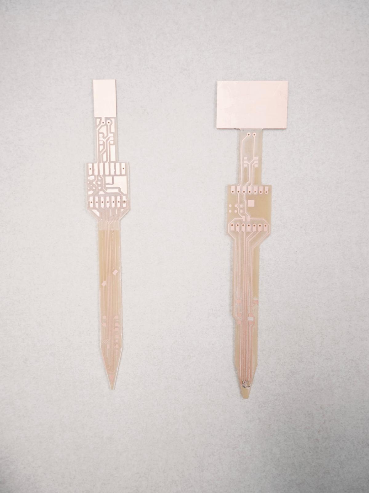
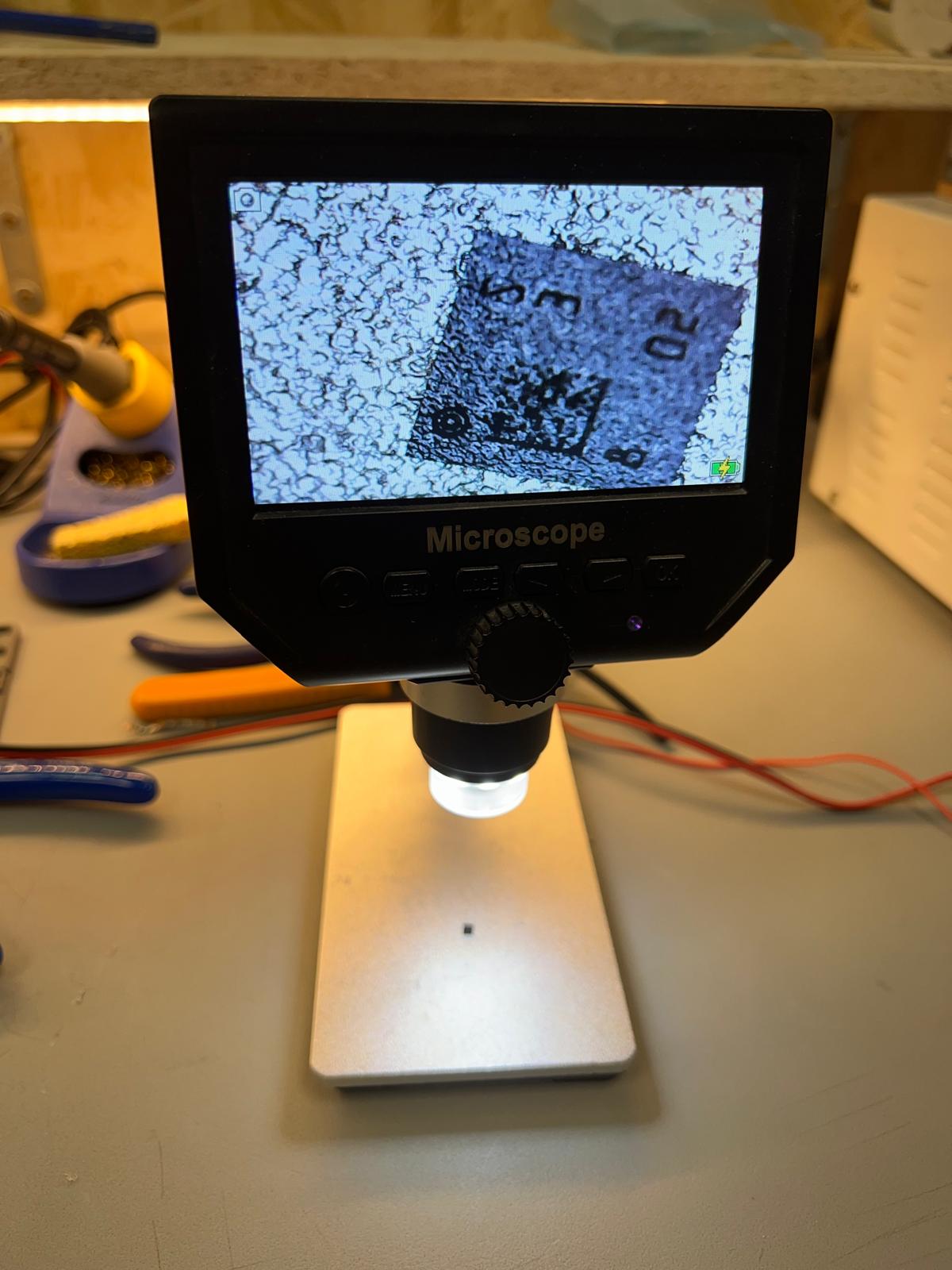
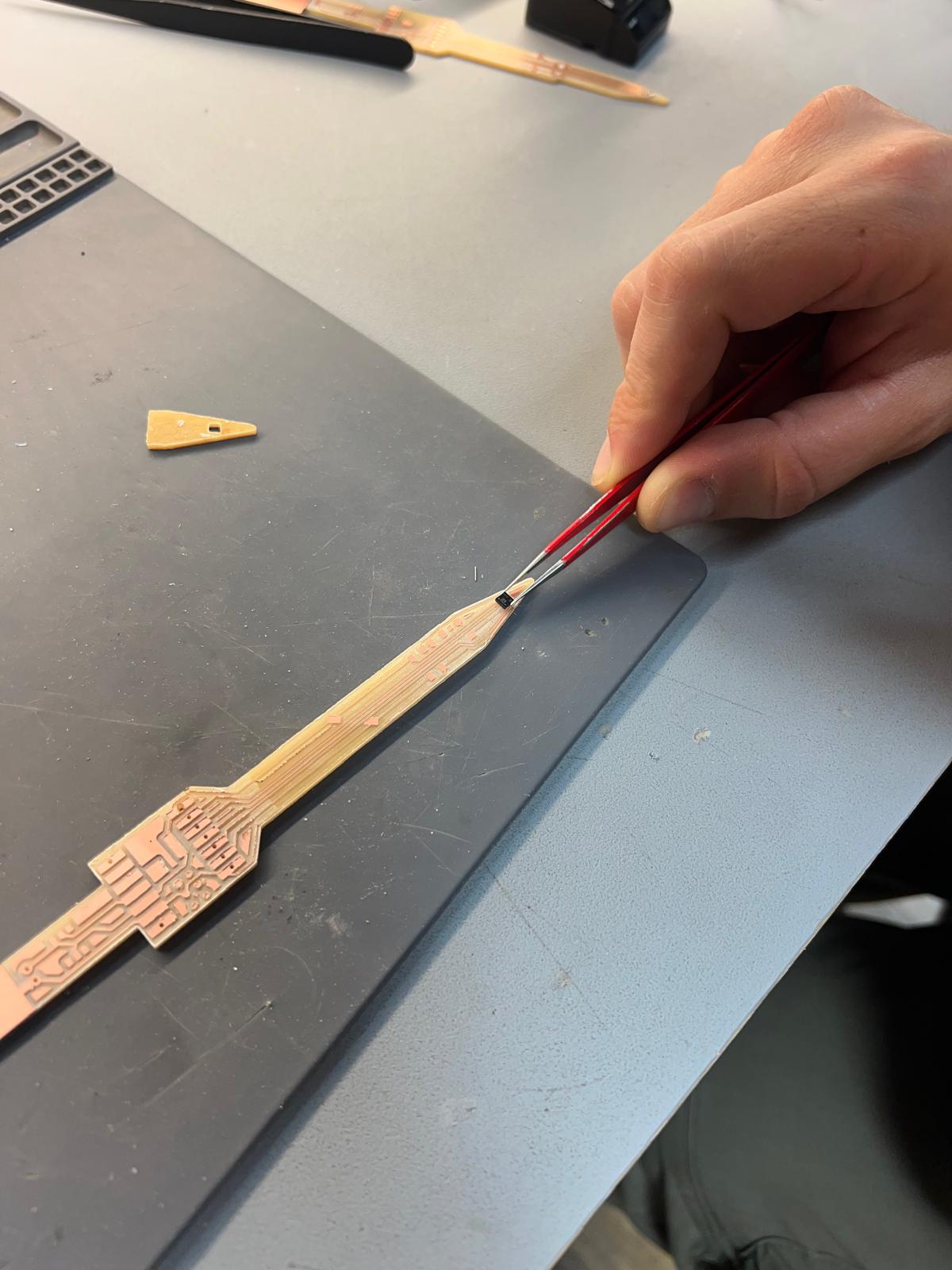
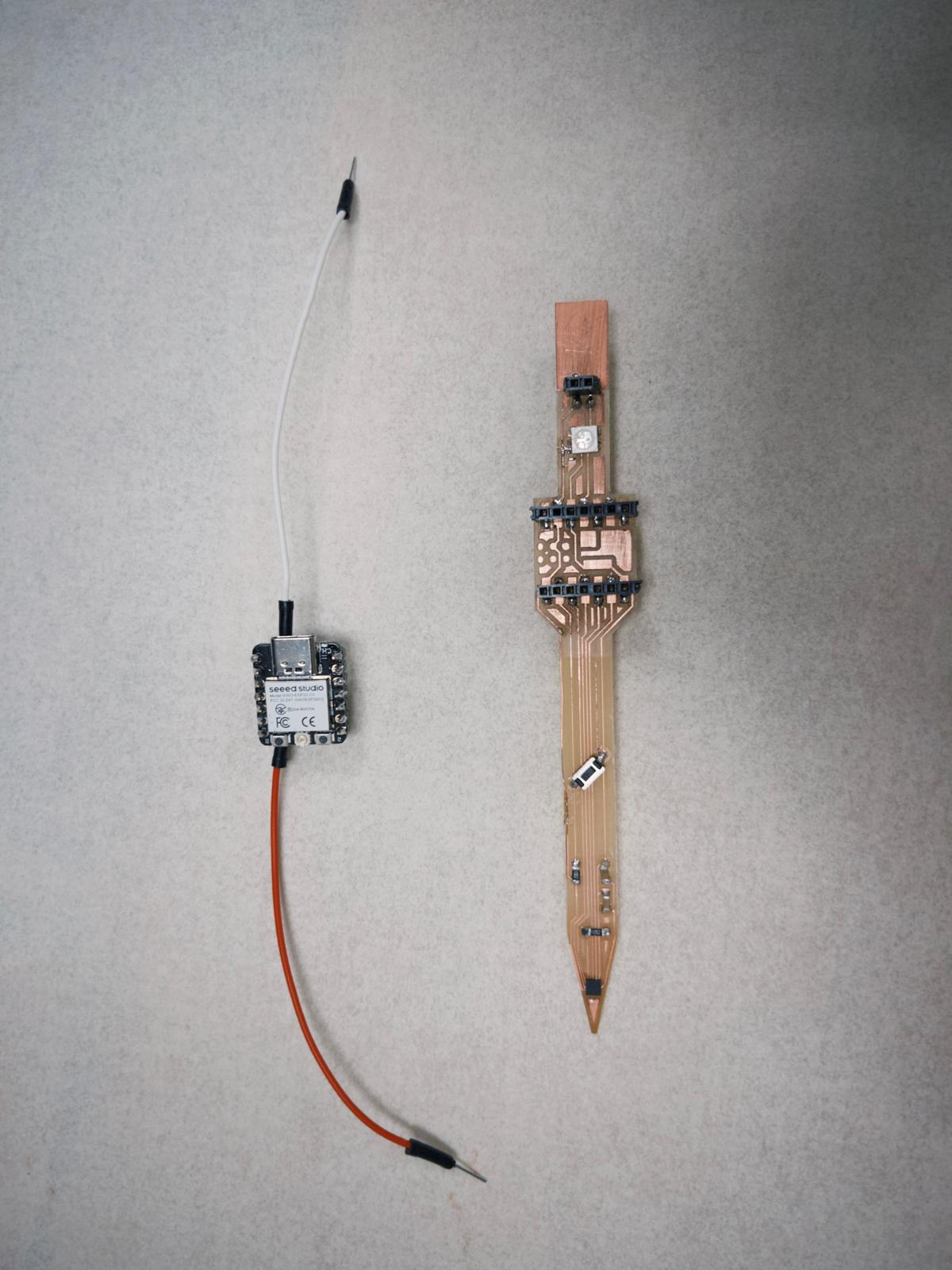
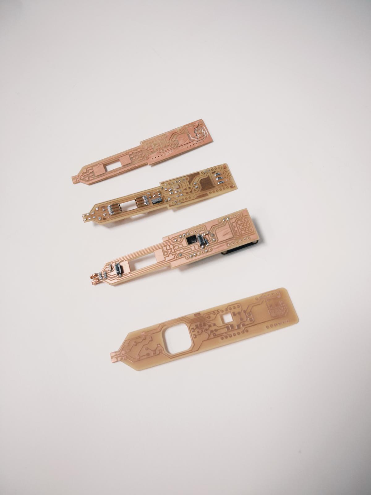
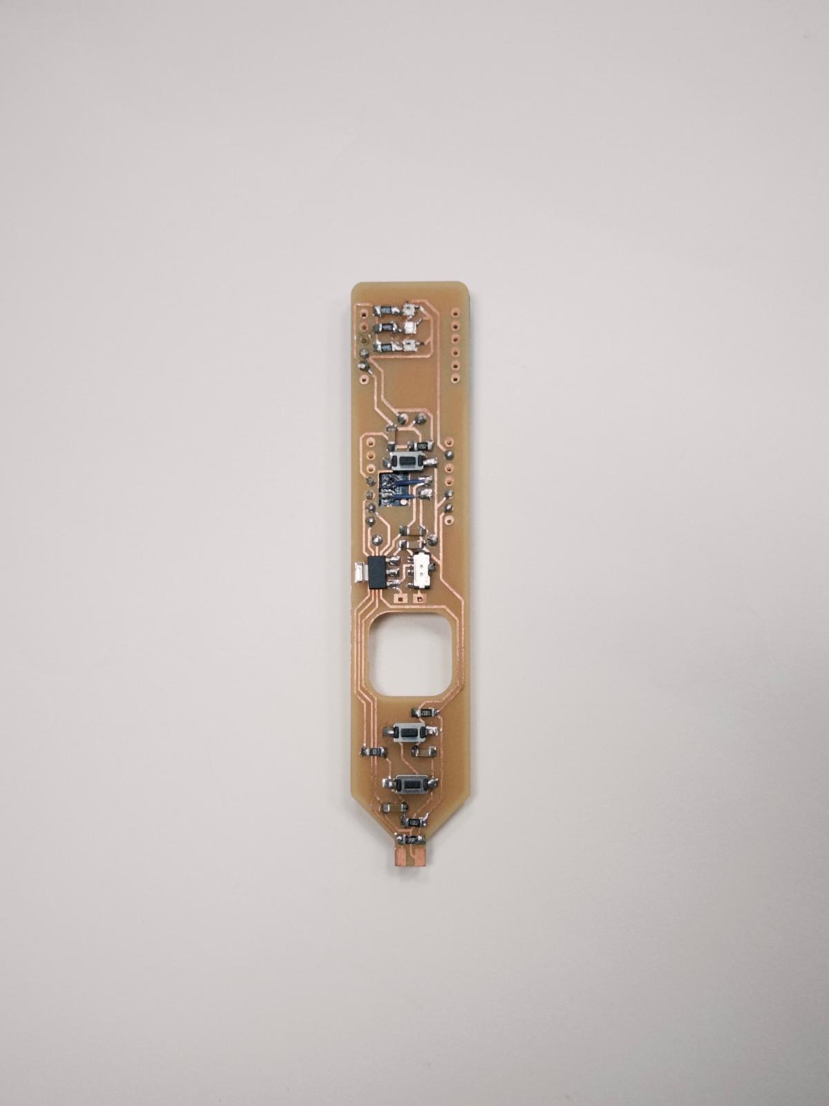
Week 12 / I had trouble with my first PCB (on the right). I tried cutting with the standard 1/64" end mill and it wasn't thin enough to cut through the pads of my accelerometer. Which is really small. The second PCB had its tip cut with a 0.01" end mill, which after breaking one end-mill, worked. Soldering was the next problem, it's hard to tell if all the pins are properly connected.
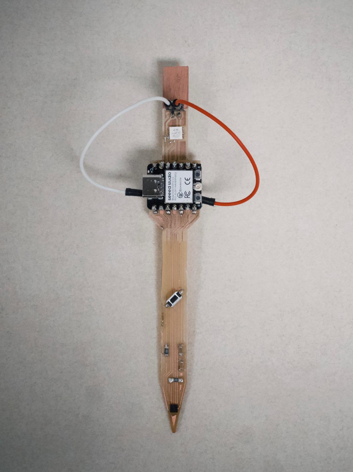
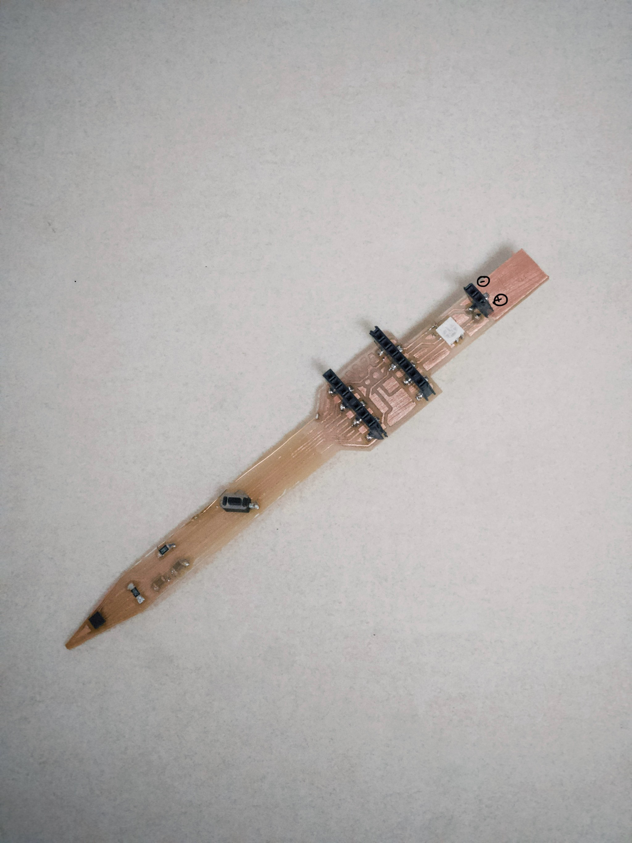
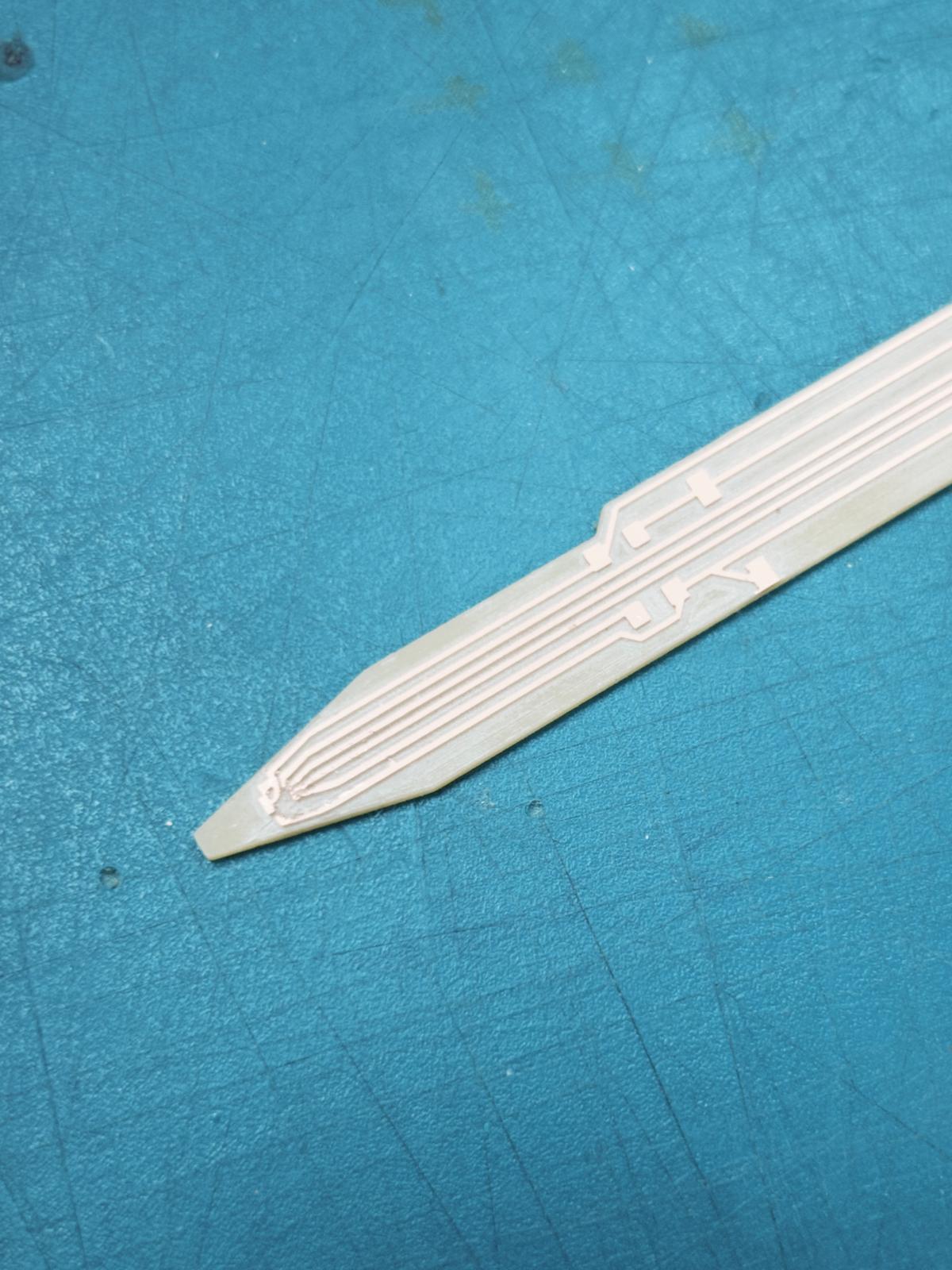
Week 12 / The design of the first spiral should have been quite straightwforward. The main goal was to make sure the accelerometer was in a realistic position for the tip of the pencil in order to properly translate the data from it. Aside from the sensor, there is a neopixel and a button to activate the sensor. I made some mistakes, as I forgot to include a resistor and capacitor for the neopixel, and also pull-up resisors for the SDA and SCL lines.
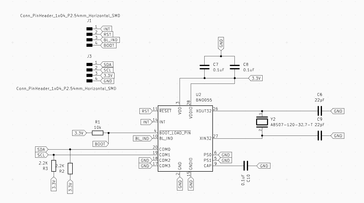
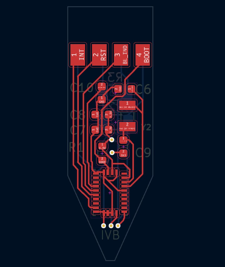
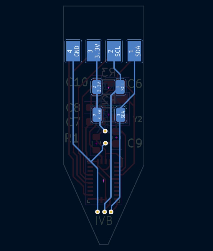
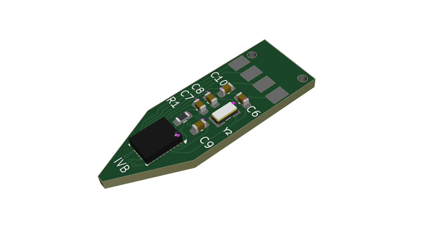
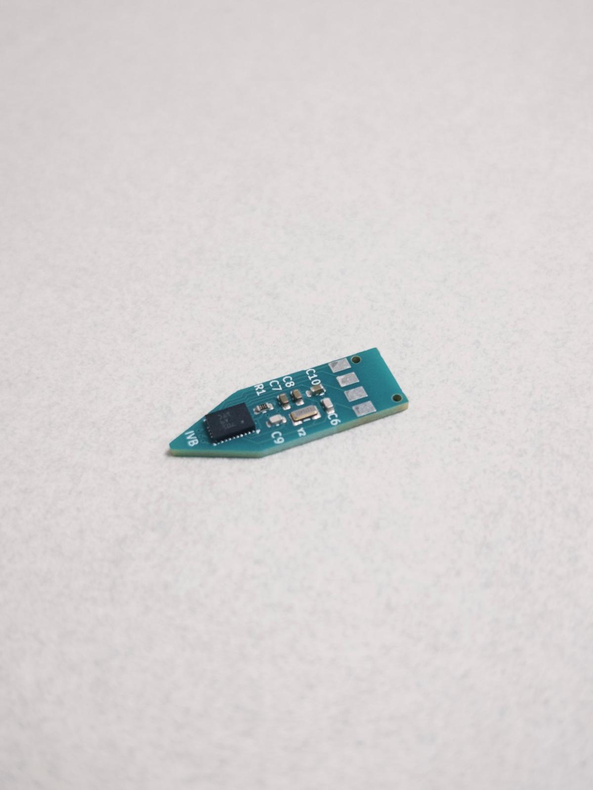
Week 15 / Sent a custom PCB for the tip of the pencil to a PCB house! Worked on the design for the BNO055 sensor on the tip of the pencil. The goal of this process was to make sure the sensor was properly soldered to the PCB, due to the previous struggles trying to achieve this manually in the fab lab.
Week 14 / During interface week, started translating accelerometer data into Processing sketches. Haven't reached any level of accuracy and real control over the tool, but, can achieve the some scribbling with a button on the board.
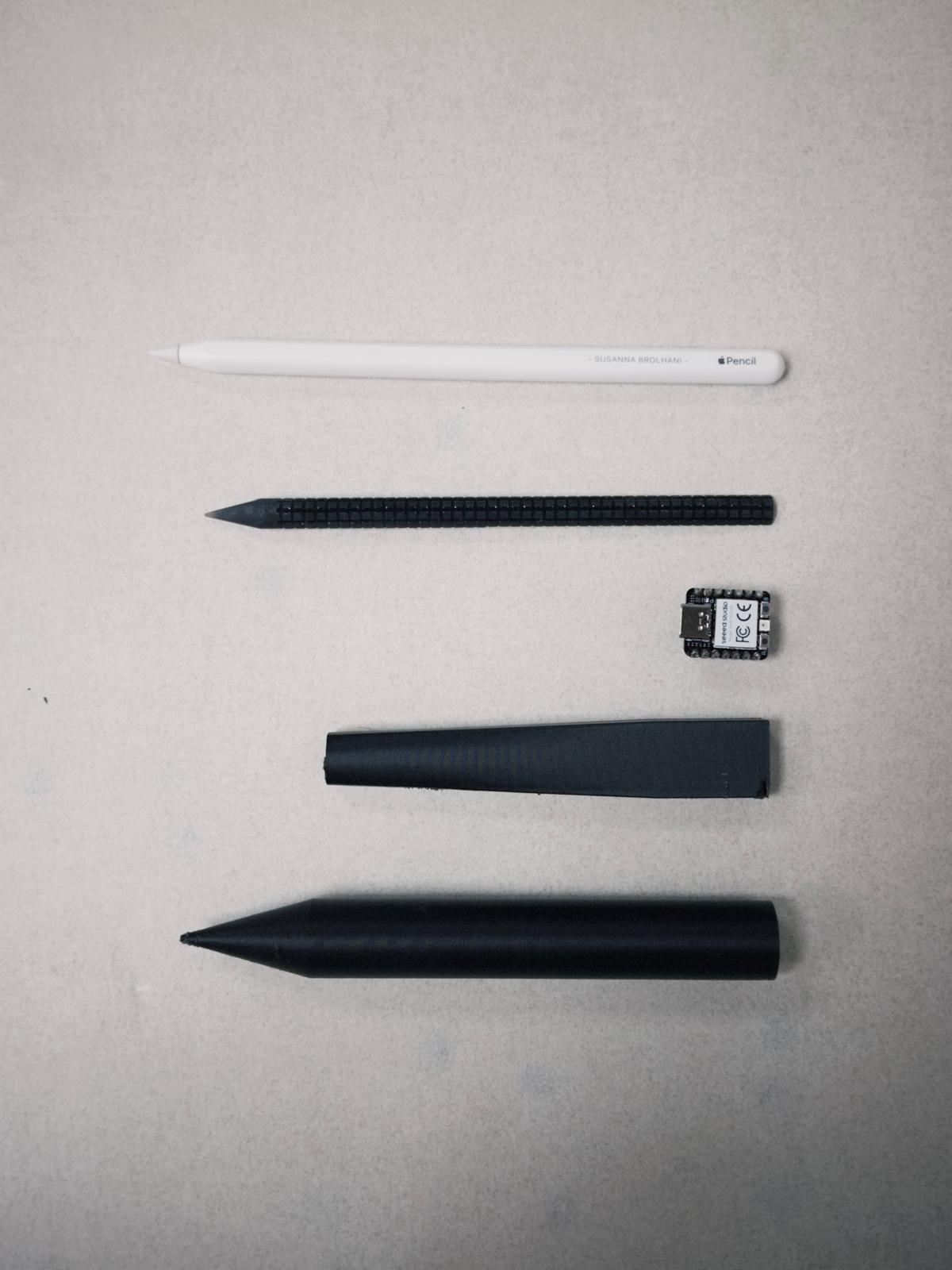
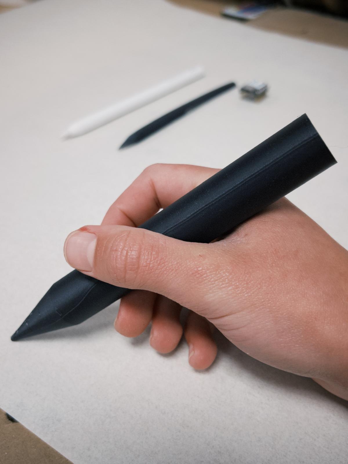
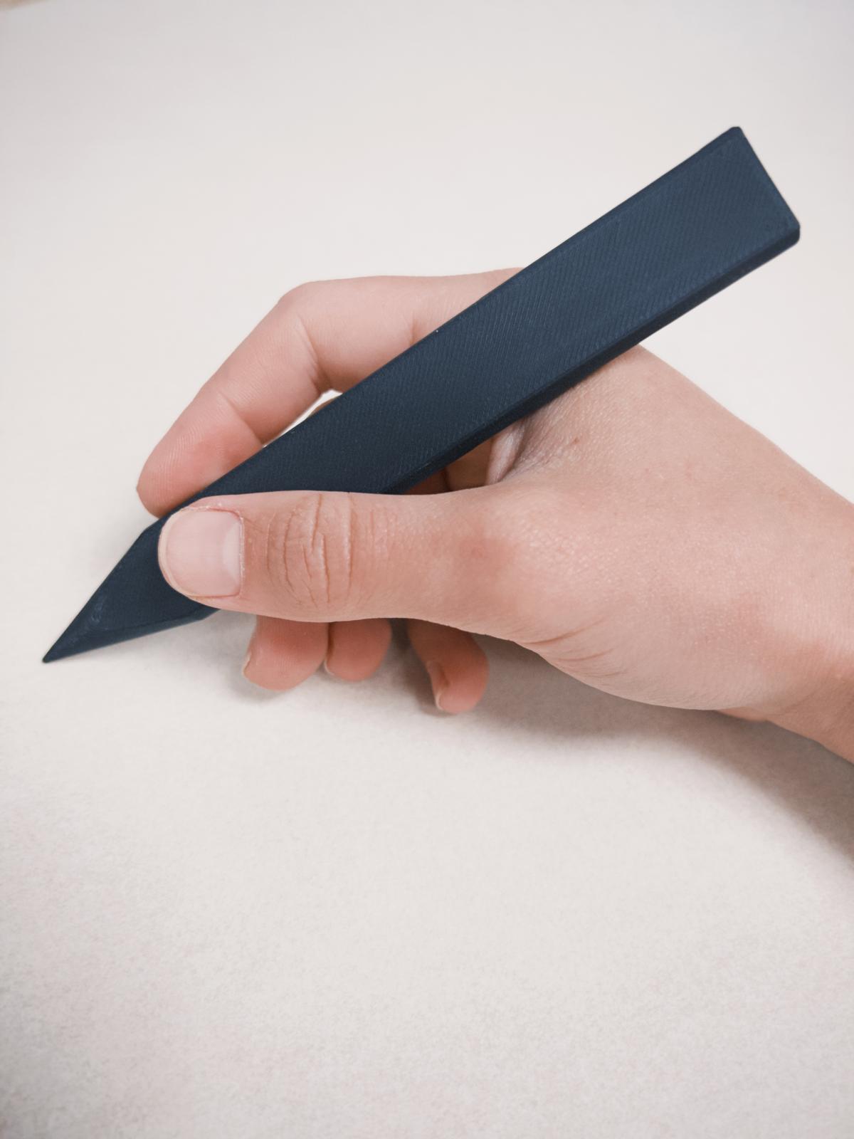
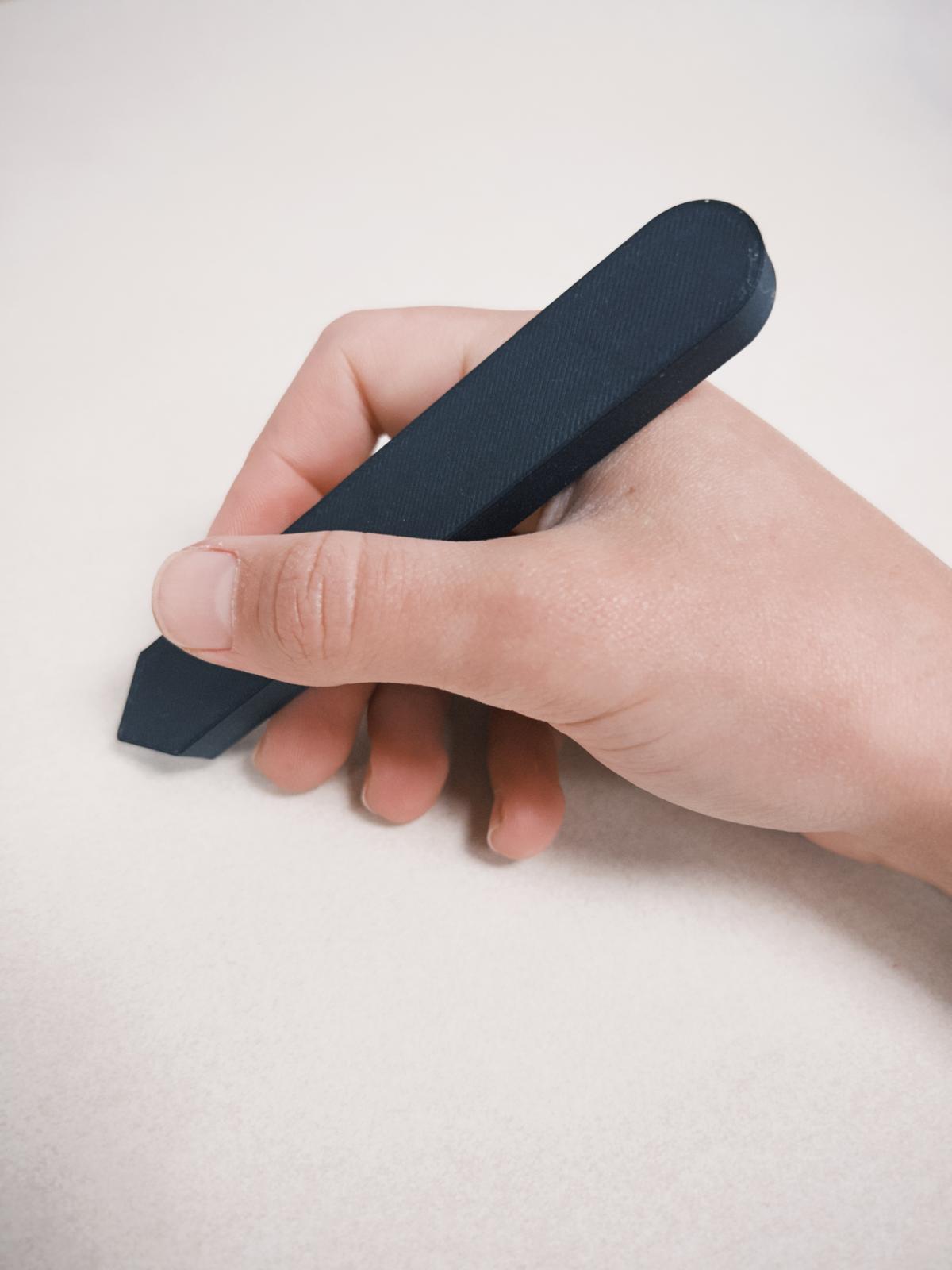
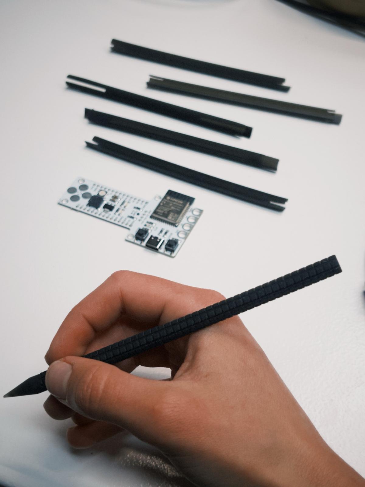
Week 16 / System integration week, developed further the geometry, in hopes to reach the desired interface. I knew it would unlikely fit my desired shape/size. See pics above for size comparision.
Then Emily saw the crayon looking one and pointed out to this marvelous masterpiece (Harold and the purple crayon!), which was unfamiliar to me. However, I felt represented by his fascination for the moon and desire to draw anywhere. source of the video.
Week 16 / During Sytem Integration week, finally designed the full PCB and the required parts for the functions I would like to implement in the initial stages. Also, my custom PCB from the PCB house, for the accelerometer arrived. It didn't work initially and along with the instructors figured it could be one of the connections in the wrong place (the kiCAD symbol I used had a couple connections different than the datasheet, we assumed this was the fault). Given that I couldn't spend much time troubleshooting this delicate piece of electronic, I decided to design a system with the Adafruit BNO08x. Sad due to the size part, but reliable to carry on.
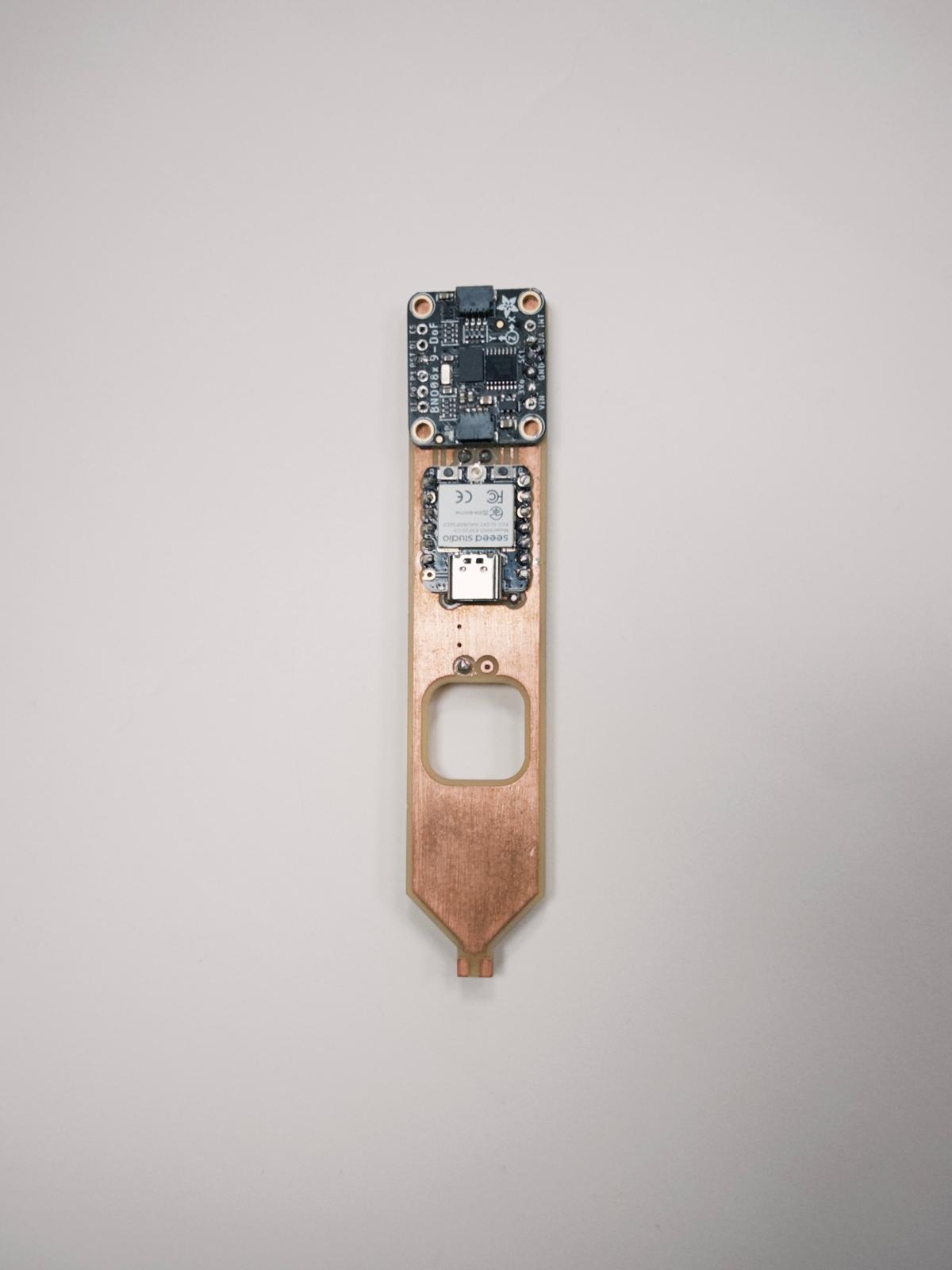
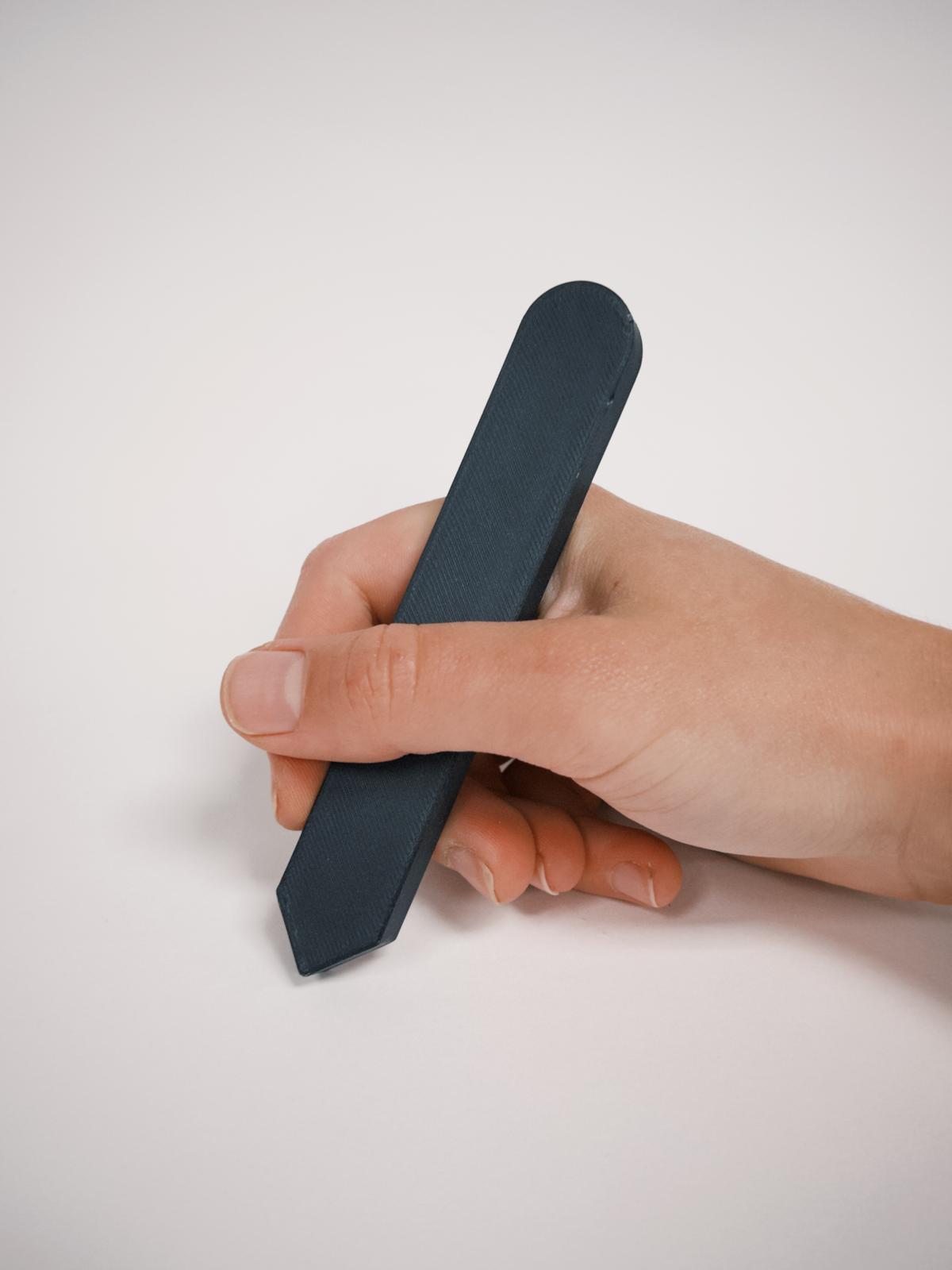
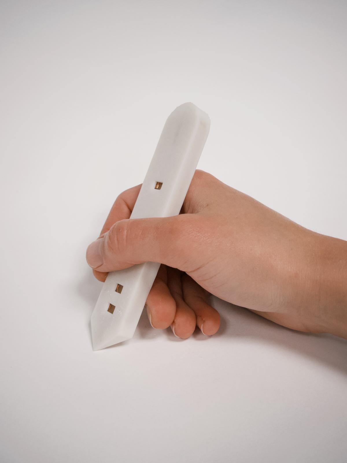
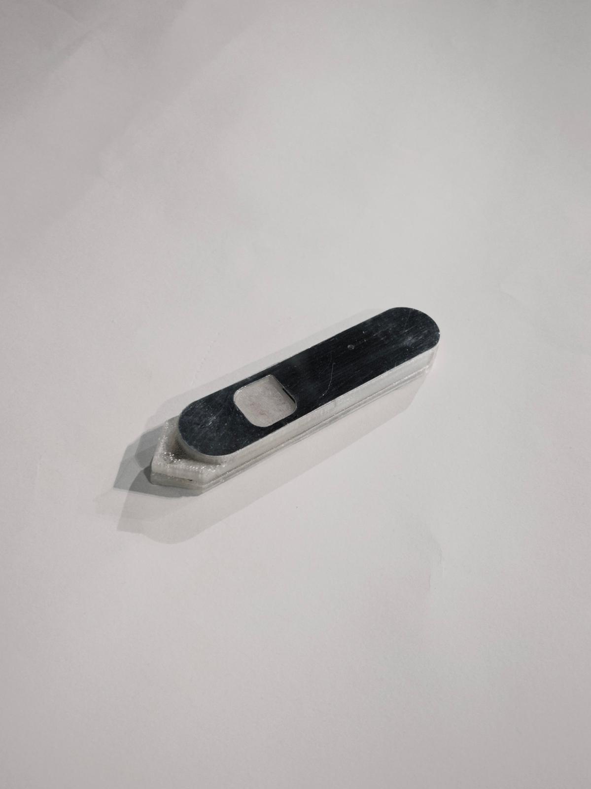
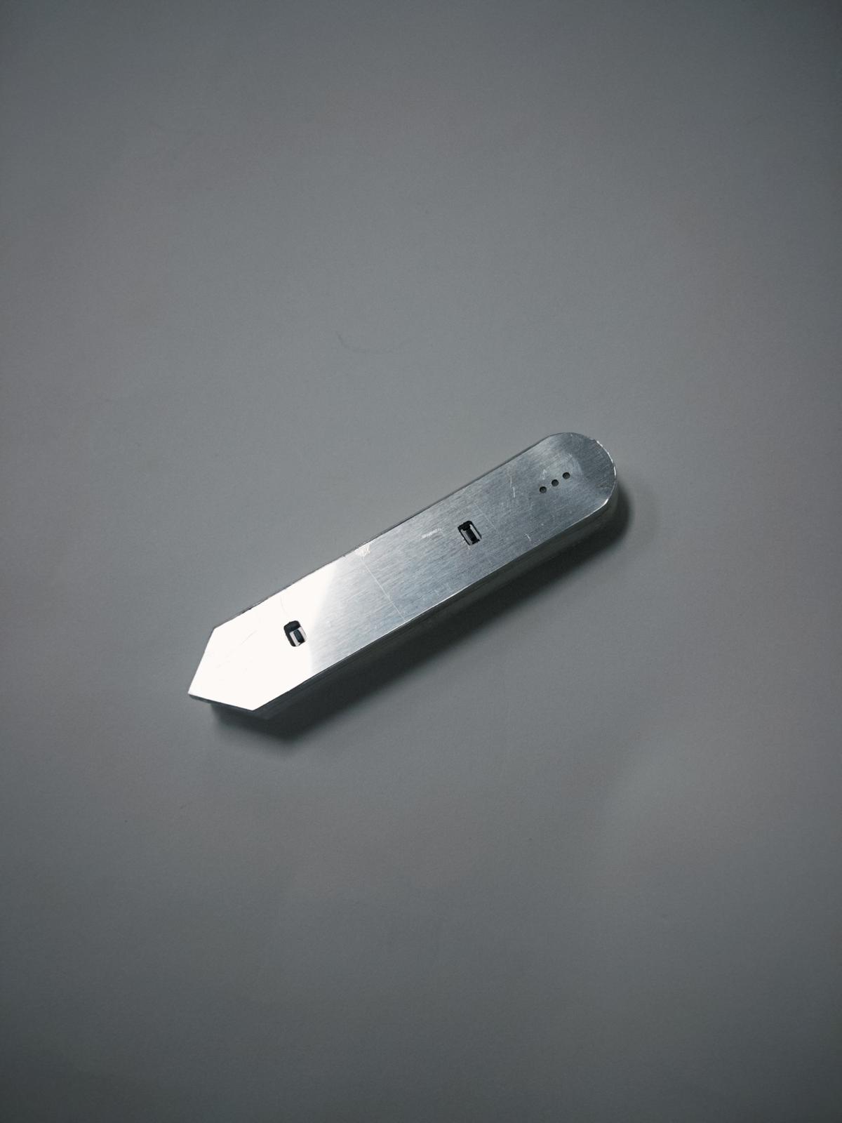
Developed the outer case to hold the electronics together. The one on the left is the FDM print, part of a geometry study. The one on the right is the resin print that was developed inspired in the idealized shape - but considering the internal PCB parts.
I had problems with the SLA print of my final pieces however, and realized I had to implement a substractive fabrication method to fulfill the final project requirements. So the final design was a FDM print case with 2 layer of aluminum on each side.