WEEK 4 / ELECTRONICS PRODUCTION
The goal of this week was to learn how to mill/cut copper and solder components onto them. To make PCBs!

Weekly assignments
Group assignment
TASK: Characterize the design rules for your in-house PCB production process; send a PCB out to a board house.
You can find the group assignment in our group page.
Individual assignments
TASK: Make and test a microcontroller development board
extra credit: personalize the board
extra credit: make it with another process.
For this assignment, I made a Quentorres board.
PNG Files:
RML Files:
MODS cheatsheet for PCB milling:
TRACE: speed 3 / height 5
HOLE: speed 1.5 / max height 1.75
CUT: speed 0.5 / max height 1.75
I set up the files for the milling machine on https://modsproject.org/. The program was Roland > SRM 20 mill > mill 2D PCB.
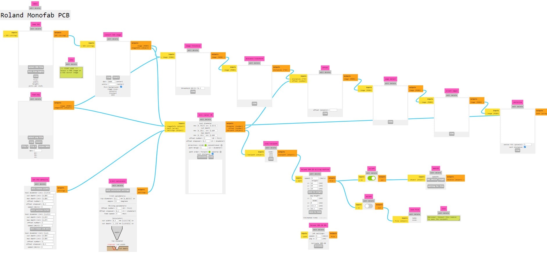
I uploaded the "traces" PNG and clicked on "get default parameters for tracing".
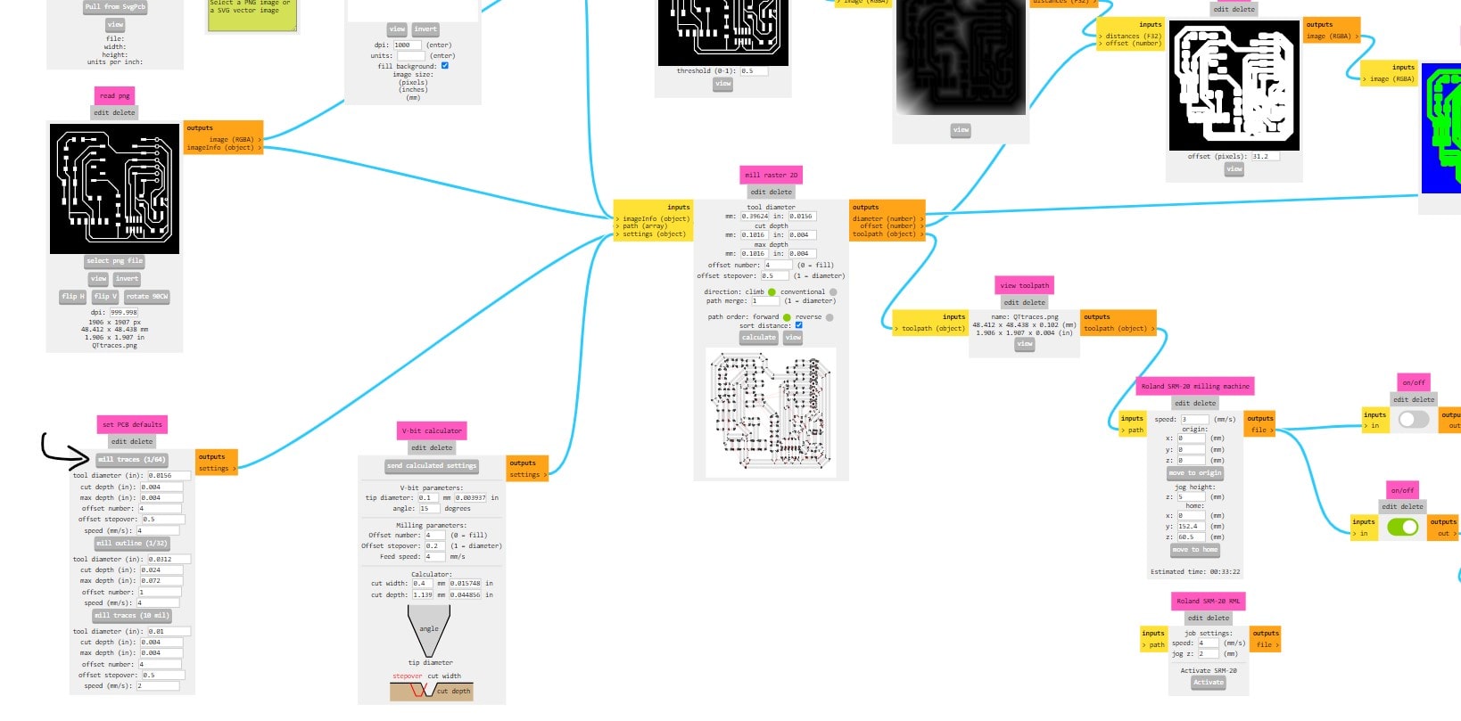
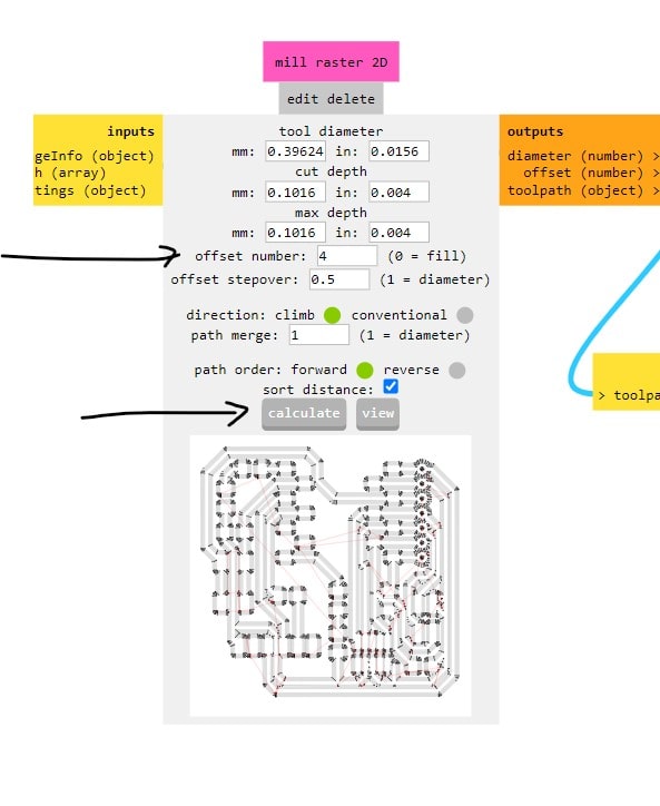
Then these were the settings I used for tracing:
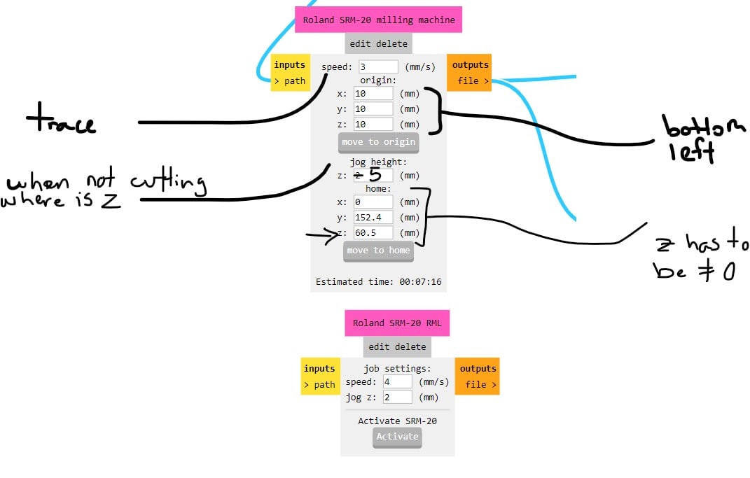
Had to make sure these were the toggles in the output - in order to save the RML to PC;
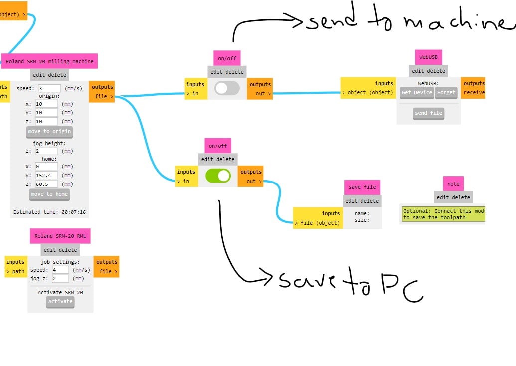
These were the settings I used for calculating. Then, pressed calculate to save the file.
For the outline file, repeat the steps, but grab the default setting in the mill outline button.
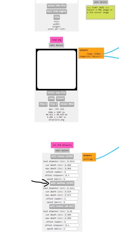
make sure have this setup:
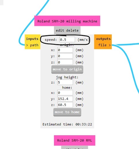
This "max height" setting had to be adjusted, which had been tested before and was enough to cut and not damage the base.
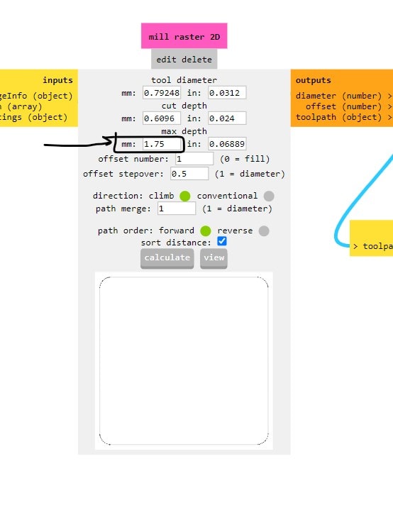
Repeat for the holes file:
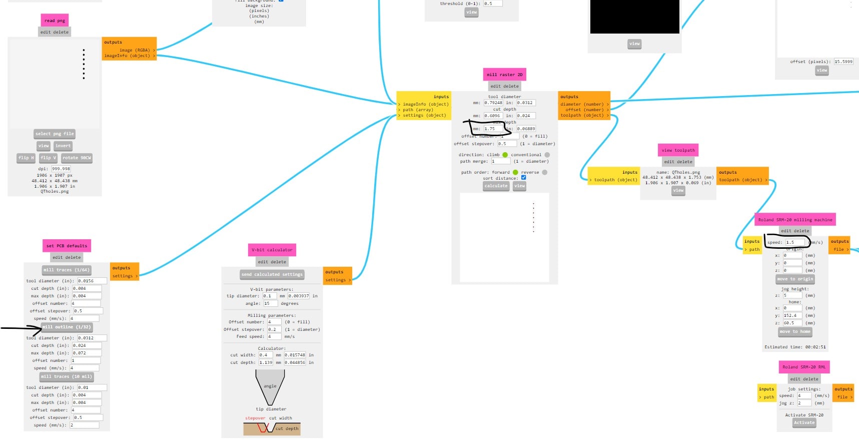
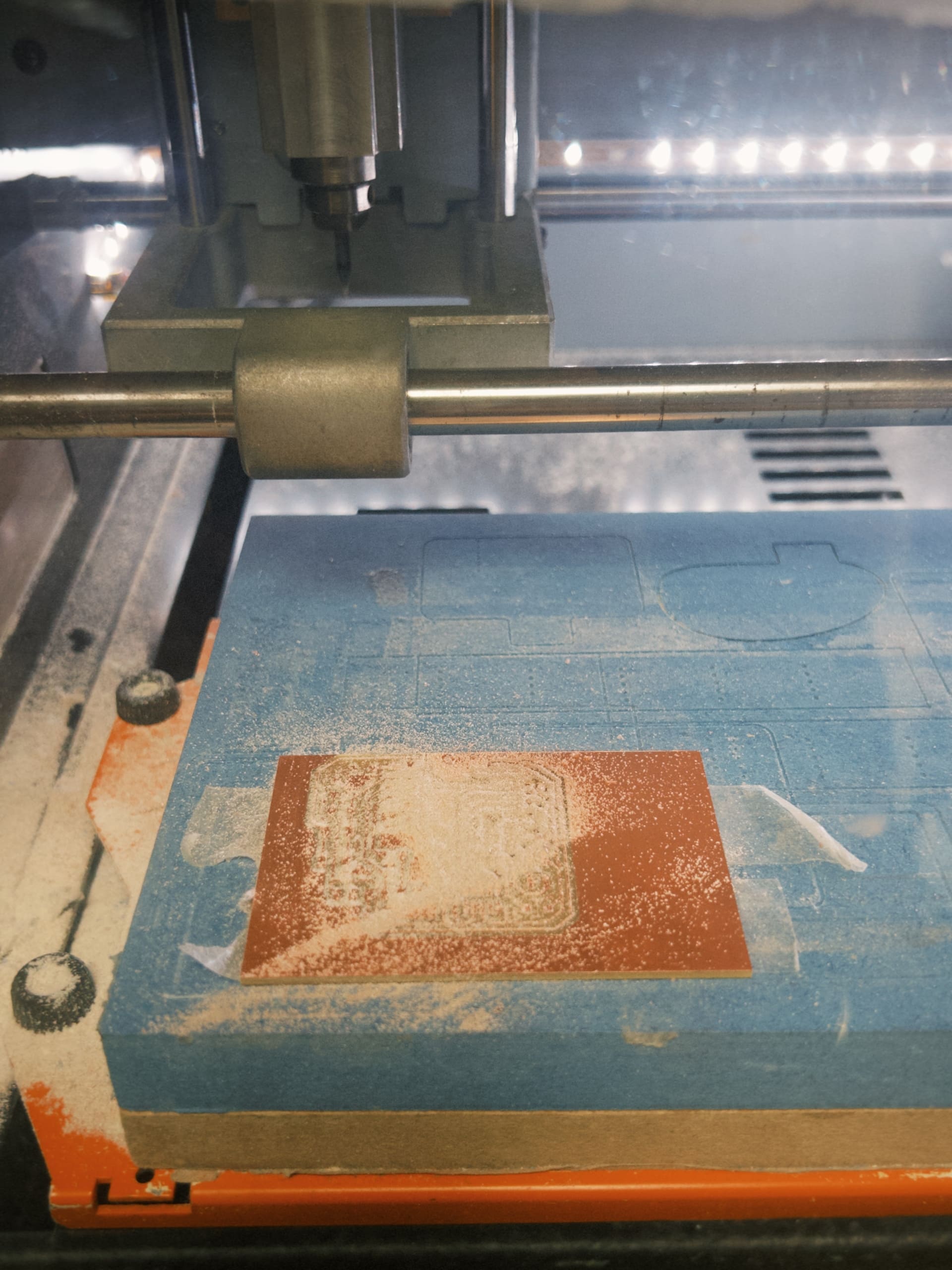
Great! Now securely tape the material on the base of the machine and make sure everything is nice and flat, hopefully no bumps:
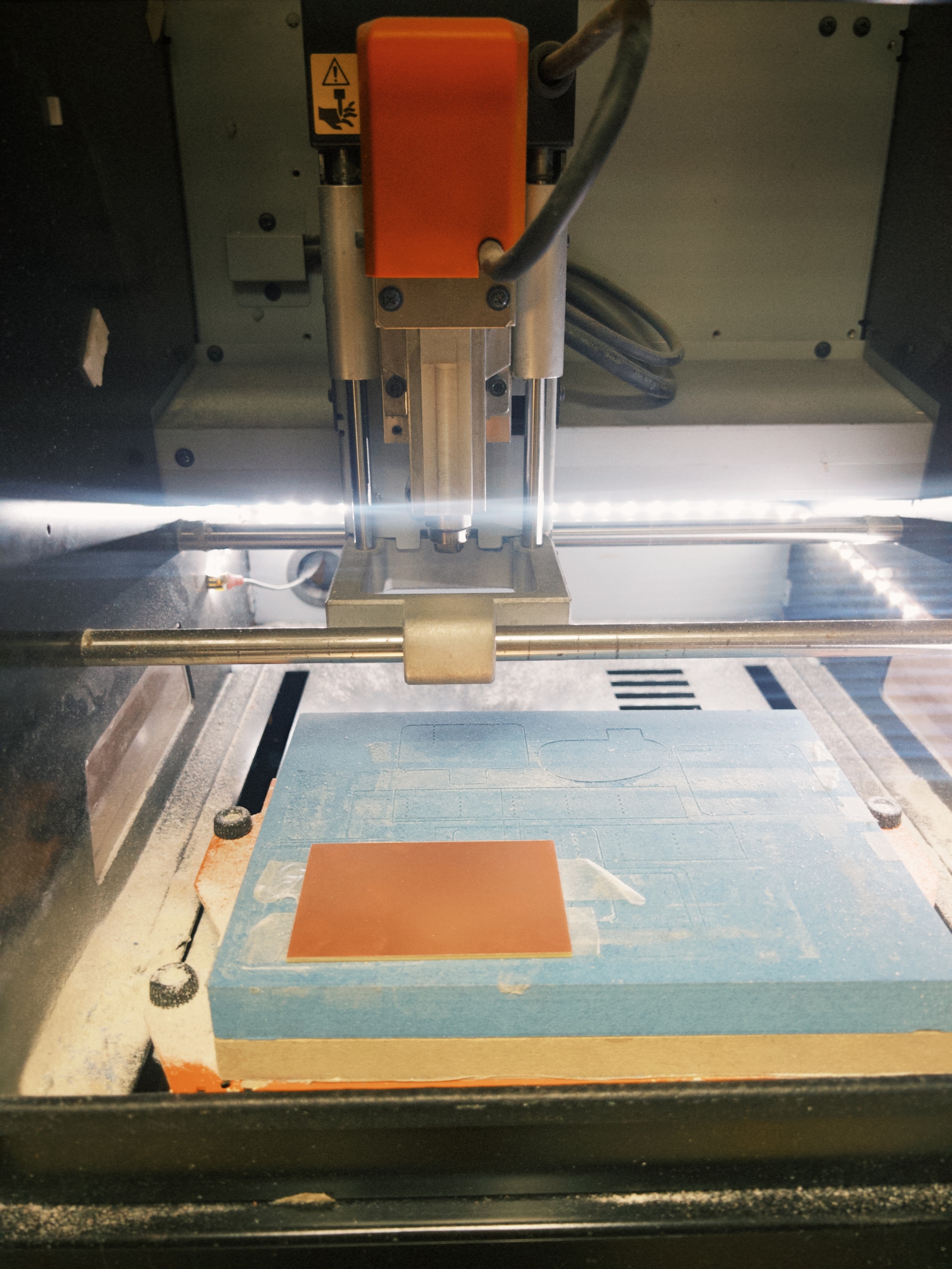
To setup the mill: set the XY origin with the arrrows, then press X/Y origin point when reach the bottom left of the material. To set up the Z, slowly move the mill downwards until almost hitting the material, THEN a trick is to unscrew the mill and let it drop to the surface of the material, screw it back and set Z origin.
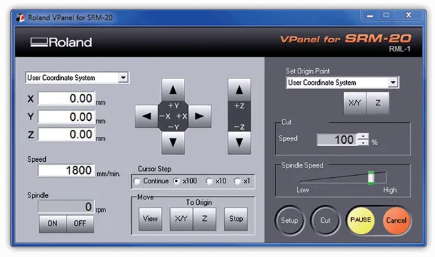
Then go through the 3 files and cut it
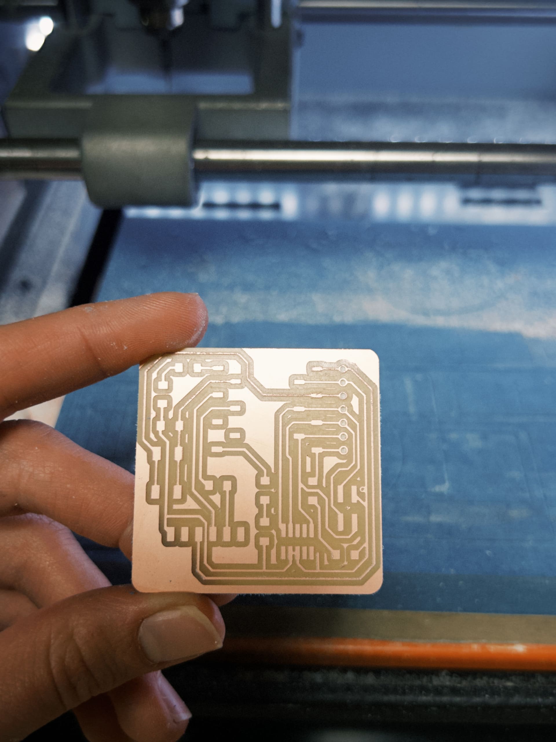
Collect the thing, clean the dust and also wipe with some alcohol or surface cleanser.
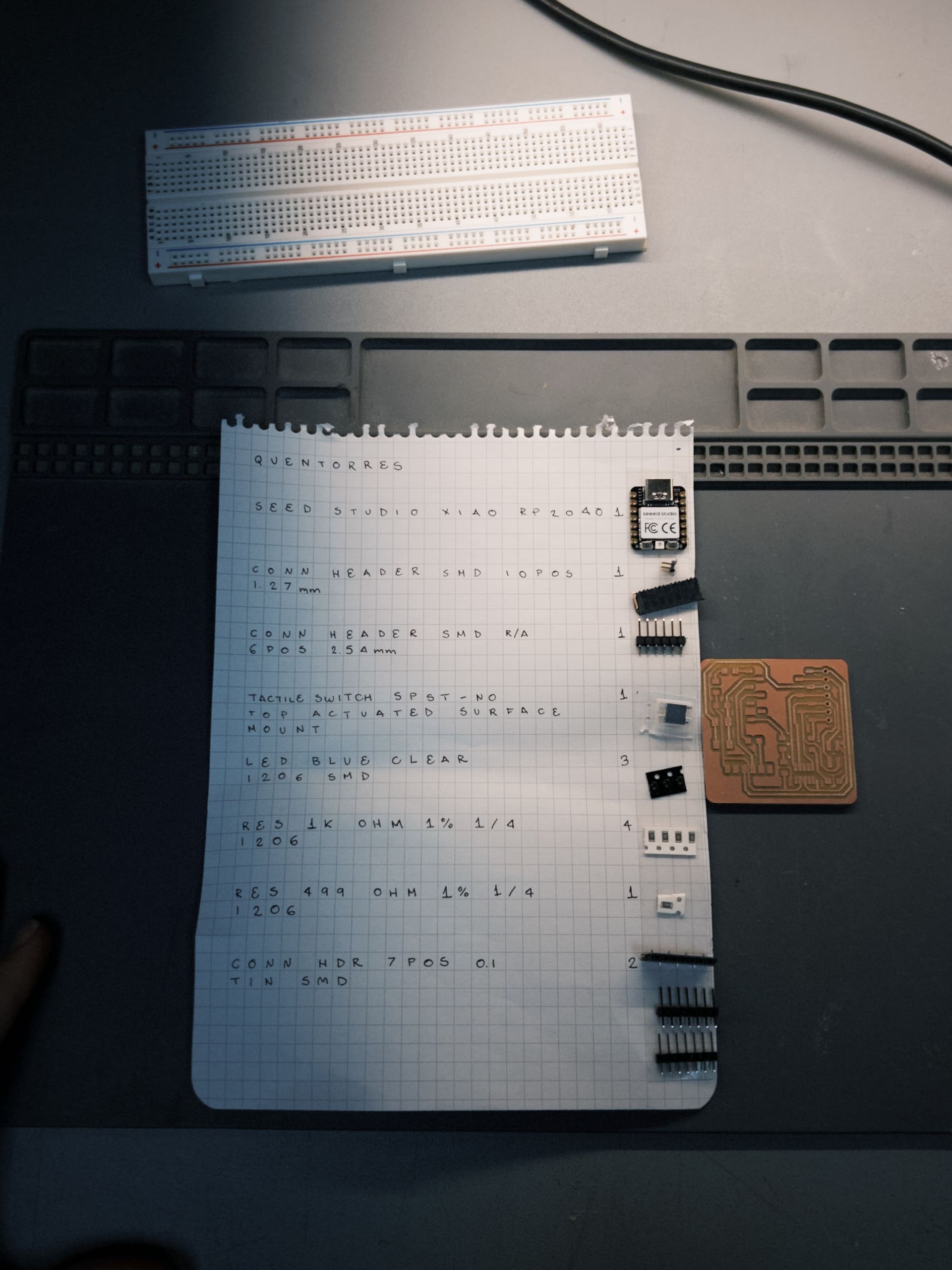
For the Quentorres board, these were the components. Then started soldering the components into place:
Done with the board. However, tried running a test and realized some parts of my solder were not sufficient. If you look closely you'll see my LED is flaoting on top of the solder. Had to do some fixes around it
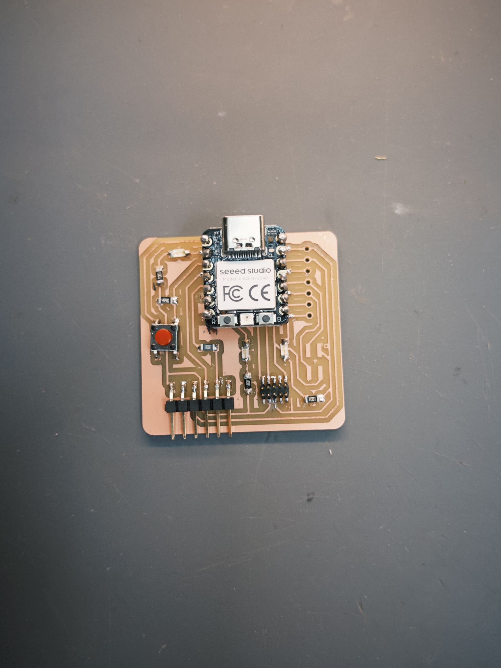
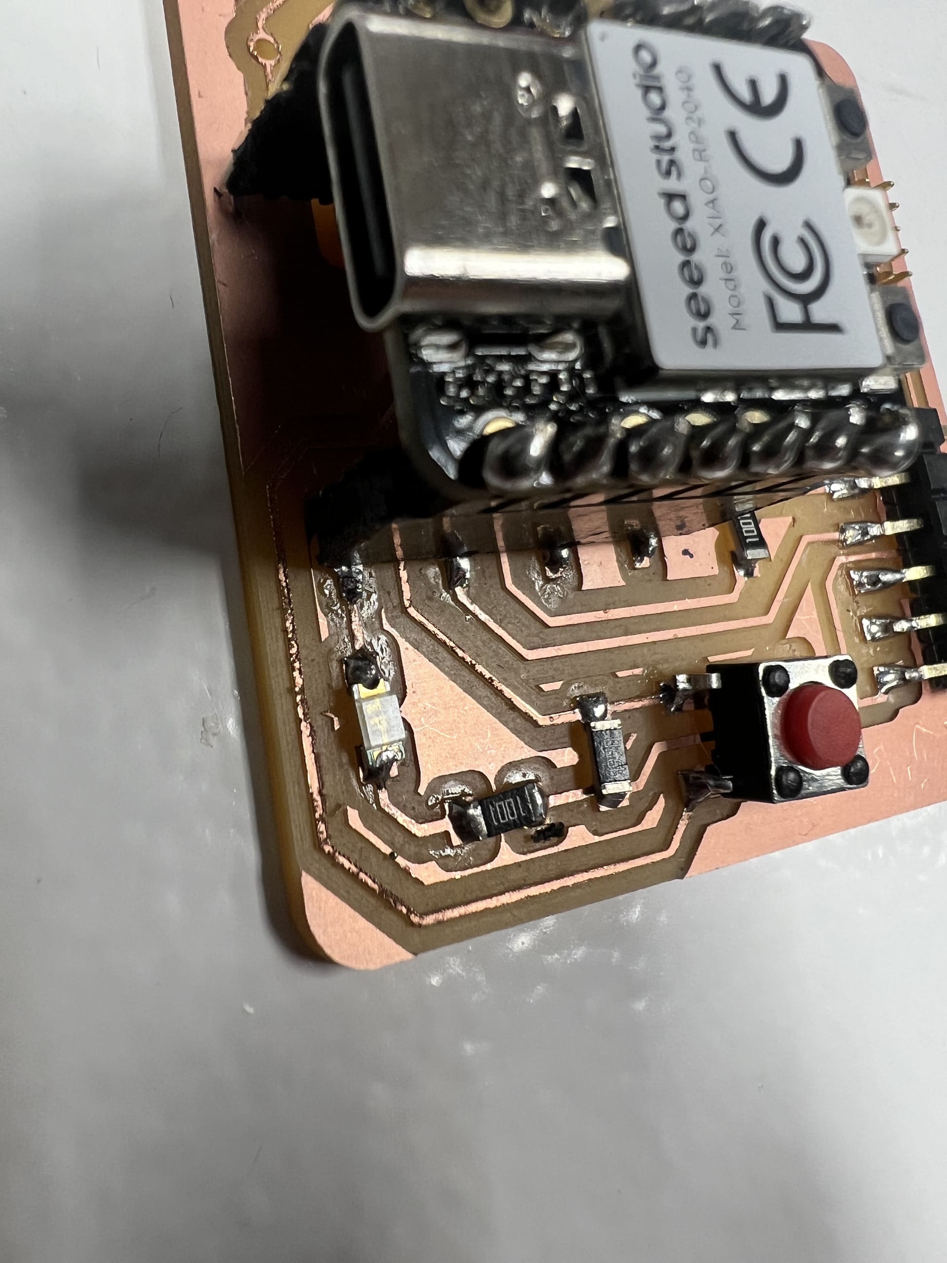
After making sure my circuits were working. Ran the blink test.