Week 8: Electronic Design
The assignment:
1. Group assignemt: LINK
2. Individual assignment:
Use an EDA (Electronic design automation) tool to design a development board to interact and communicate with an embedded microcontroller.
Background
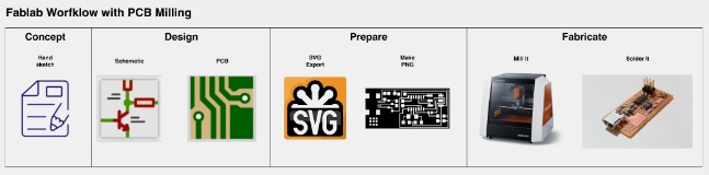
EDA is a category of software tools for designing electronic systems such as integrated circuits and printed circuit boards. At the lab we use KiCad. KiCad is an open source, cross-platform Electronics design program The tools work together in a design flow
What I did
Concept
For the electronic design I want to see if I can design a humidity sensor that is programmed to turn on a servomotor when a certain threshold of humidity is crossed. (Later I might expand with other outputs) My flowchart looks like this:
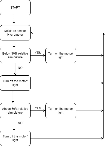
For now I will try to do simple circuit that gives an output to a high moisture level. My components for this are:
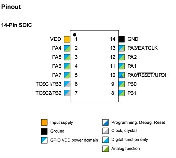
In the datasheet I find an overview of the pinouts
Design – Schematics in KiCad
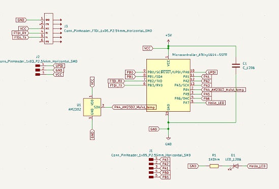
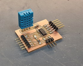
Earlier I had downloaded the library with the components that are available at the lab. I inserted the components in the schematic editor and designed the schematics like this:
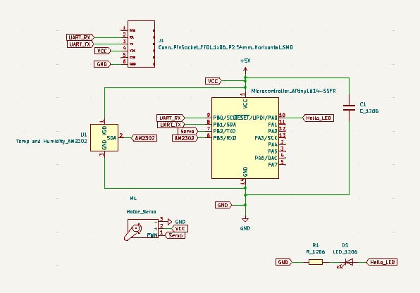
BUT I am struggling with the route tracks for this PCB with the sensor and the servo. I cannot find a way to wire alle the connections at the moment. So I need a little more time to get it right…..Therefore I re-designed everything by taking out servo and putting in some outpur pins in instead. Now it looks like this
Design – PCB Editor in KiCad
I was now able to wire the schematic and it looked like this:
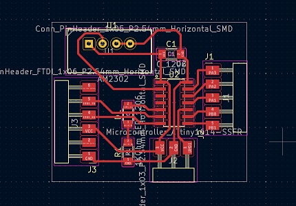
See the design file (KiCad) for the board here
Notice the settings for the Board setup. To make the settings choose
Under netclasses I chose 0.4 mm for clearance and 0.3 mm for track width
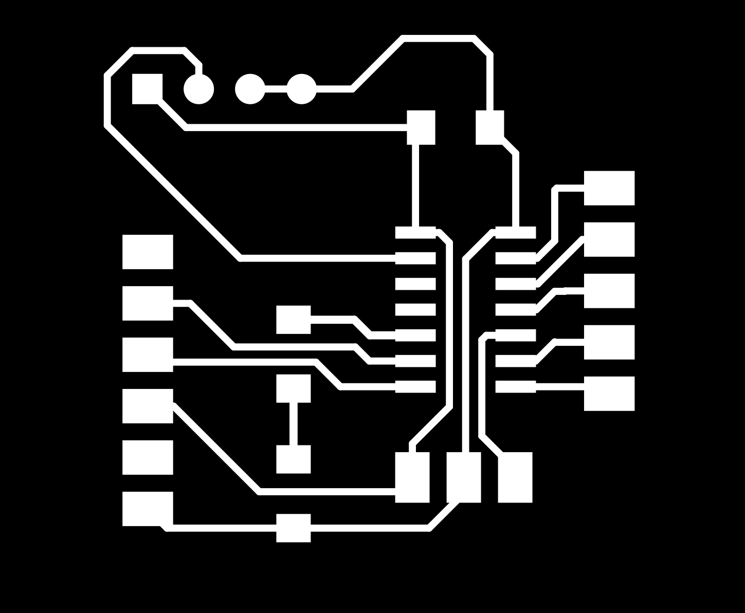
Next step for me was to create *pngs of the traces, holes and outline in Inkscape that I the could open in mods to make the settings for the Roland SRM-20
The files are here: Traces Holes Outline
Prepare – Mods
To prepare the file for milling I used https://modsproject.org/ and the same procedure as I learned in week 4. See how here
Milling and soldering
As I had to go to Denmark for 3 weeks and did the milling when I got back.I milled the PCB like I learned in an earlier week
Same procedure as I learned in week 4. See how here
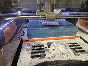
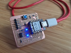
And then I soldered the PCB with the components mentioned above. This is the result:
How I programmed my board
In order to programme the board I went to the Quentorres page LINKFirst thing to do was to take my PCB with the RP-2040 on it and flash it to make it ready for use as a programmer by installing the *.uf2 file that I downloaded from the website.
The file is hereAfter reset (push B and then R) the device appeared as a drive and I copied the *.uf2 onto it. The board did automatically reset after moving the file to the drive
The device also showed up as a connected USB device on my PC, - so it should be functional
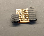
Next step was to design a connector for connecting the PCB with the rp-2040 and the PCB with the ATtiny 2040.
I used the *png files from this page to mill the board for it:LINKAnd downloaded these 2 files to mill and solder the board. Traces and Outline
This is the result:
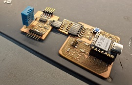
And here are the 3 PCBs connected:
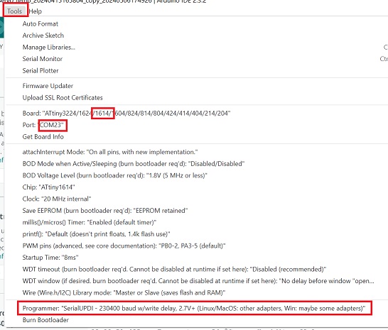
Next step was to flash the target through the Arduino IDE. Here I first installed the megaTinyCore. I used the URL: http://drazzy.com/package_drazzy.com_index.json and added the ATtiny 1416 to my boards. I also select one of the SerialUPDI options, and made sure I had selected the right port. Now the ATtiny should be installed. Unfortunately it didn’t and I started checking for possible sources for the faults. In the end I tested with another programmer and succeded.
The programmer I used here was a so-called UPDI programmer.
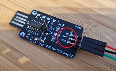
I connected the pins for UPDI, GND and 5v to the according pins on my board. Now I could programme my board using the programmer. This is the setup in Arduino IDE:
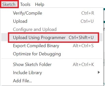
After that I used did this to upload the code:
The code for the blink test is here: BLINK code
When the code was uploaded I had to rearrange the setup to create serial communication:
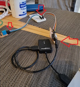
USB connection to Quentorres >Quentorres 6 pin connector to breadboard>from breadboard to 6 pin connector on my board. I know this isn´t going to work well when it comes to packaging for the final project, - but for now it works.
Here you see the working Blink test: