Week 4: Electronic Production

The assignment:

1. Group Assignment

2. Individual Assignement:

  • Make and test the development board that you designed to interact and communicate with an embedded microcontroller
  • Reflect on PCB production process
  • PCB – printed curcuit boards

    PCB board

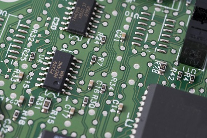
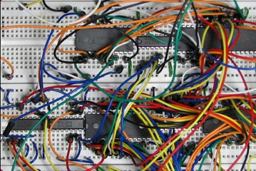
    PCB boards are used in all electronic devices that we use today. So it is important to understand how these curcuit boards are designed and integrated into devices. Both from a environmental point of view (which materials are used, how is the production process etc,) and because it makes it possible for us to customize the PCBs to specific needs of our projects. The reason why it makes sense to print your own PCBs is also because it is a way to control all the wirings and reduce chances of errors like short curcuits. Its an alternative to using breadboards, jumpers etc.

    Breadboard

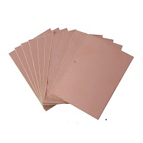
    There are different types of boards. E.g handdrawn, vinylcut, flex-material etc. We will be using rigid, single sided FR1 material – because it is low cost, it has good electrical and mechanical properties and mechanical drilling can be done on it.

    F1

    How to do it

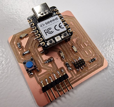
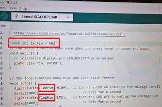
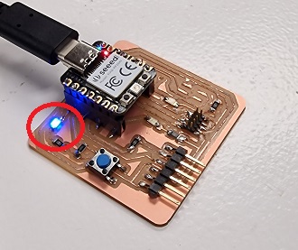
    There are different techniques. Edging (difficult to control the process and there is a lot of waste), vinylcut, fiberlaser or milling. We will be milling and the whole process consists of cutting the board>selecting the components>soldering>doing the blink test.
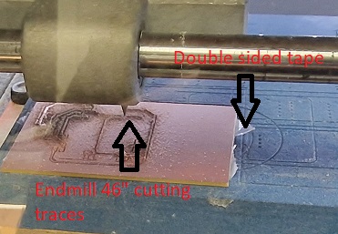
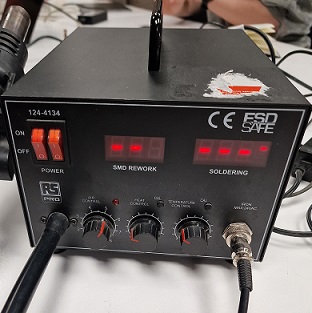
    1. Cut the board:

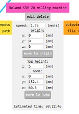
    Milling requires a machine, - in the lab we have a Roland SRM-20 CNC + endmills.

    SMR20

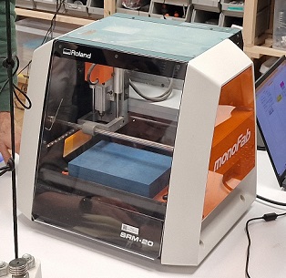
    The endmills we will be using 1/64” for the traces and 1/32” for the holes and the outline. Steps:

  • Fix the plate with doublesided tape.
  • Insert cutter 46” to cut the trace.
  • Use VPanel to do the settings.
  • VPanel

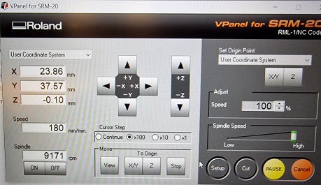
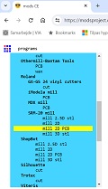
    Position the origin of XY first and save. Then carefully set the Z-origin. Do the last mm by hand (the drop) and save. The files I used were the 3 quentorres files that were prepared in mods. On the images below you can see my process:

  • First I chose the correct millingmachine and set the PCB defaults to mill the traces with a 1/64 drillbit and pressed "mill traces"
  • Mods1

  • Then I inserted the png with the traces
  • Mods2

  • then I set the speed. For traces: 3mm/s. For holes: 1,5mm/s and for outline: 0,5 mm/s. origin: X:0, Y:0, Z:0 for all 3 files. I set the jog height to 5mm and home: X:0, Y:0, Z:10mm to avoid problems when homing
  • Mods4

  • Under Mill Raste 2D I set offset to 4 and pressed calculate
  • Mods3

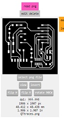
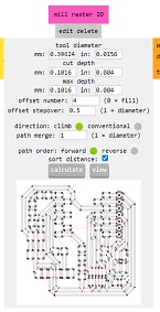
    This openened a window where I could see the toolpath

    Mods3 
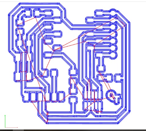
At last I downloaded the file and sent it to the printcloud.

    Then I was ready to mill.

    First traces, then holes and at last the outline – for holes and outline I changed the endmill to “23.

    Tape and endmill

    My first milling failed, because I had set the starting point a bit to high on the F1 and for the holes and outline I forgot to change to endmill “23 in the mod, so it didn´t cut through.

    Starting point

    After making some corrections I milled again. This time the result was a bit fuzzy – maybe the endmill was a bit worn or the Z offset wasn´t correct. After consulting one of the instructors we agreed to continue with this board.

    Fuzzy result

    Selecting the components (go shopping) - and start soldering

    Once the board is milled and cut you are ready to select the components. In the lab there is a wall with components to choose from. Here is my list of components that I found:

    Shopping list

    After that I chose a soldering station and some soldering wire (go for the thin) and started soldering.

    Soldering station Solder

    I tried to do the 1-2-3 movement while soldering. 1=heating the component leg and the copper with the iron, 2=adding the solder, 3=removing the iron. (To remove solder from the iron I used the cleaning sponge from the solderstation.). When I had soldered a component I checked if there was a connection through the components with the multimeter (my new best friend). This is the result:

    My PCB

    (I later noticed that i had missed to solder 2 pins. I did that after the picture was taken)

    Doing the blink test:

    In order to connect my PC to my PCB I added the XIAO RP-2040 board to the list of boards in the Arduino software with the Board manager. Having done that I uploaded the Blink program to the board. Unfortunately is was the RP-2040 that blinked and not the LED on my board. Therefor I made som changes to the code.

    Instead of writing "pinMode(LED_BUILTIN, OUTPUT);", I changed it to "pinMode(ledPin, OUTPUT);" and also added this line in the beginning of the sketch "const int ledPin = D0;" wich is the pin that connects to the LED on the board

    And then it worked.

    Code Blink

    Click here to download the Source Code.