Week 7: Computer Controlled Machining
The assignment:
1. Group assignemt: LINK
2. Individual assignment: Make (design+mill+assemble) something big
Designing a bedside table in Fusion 360
The material, a plywood board, that was given to us had these dimessions: 2500x1250x15
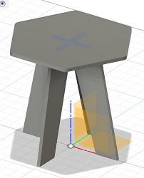
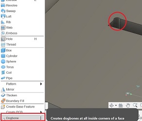
To demonstrate that I can design something with dogbone joints I designed a bedside table in Fusion 360.
I wanted the design to be mostly parametric, so I set up these parameters:
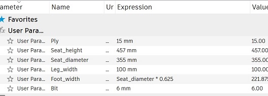
1. The thickness of the material = 15mm.
2. The height of the seat = 457mm.
3. The diameter of the seat = 355 mm.
4. The width of the legs = 100mm.
5. How far the outside of the legs are from each other. (Footwidth: half of the seat diameter + 1/8)
6. And the tool diameter for cutting out the dogbones: 6mm
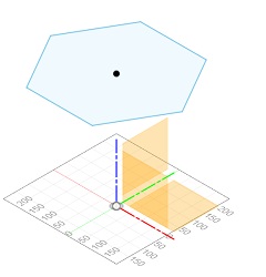
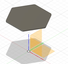
First I made a construction plane in seatheight where I made a sketch of the seat that I then extruded and added fillets to make it less sharp.
 |
 |
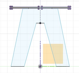
Then I made a new component for leg 1. With the line tool I drew the leg and added vertical constraints and made some of the lines colinear with the ground and the seat and added some of the dimensions from the parameters. At last I mirrored the leg to finish the sketch.
 |
 |
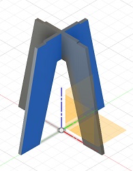
Then I started a new component and sketched the other leg on top of the first. At last I rotated it and used the combine function
 |
 |
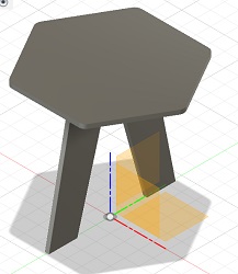
The I used the joint function to lay out the components
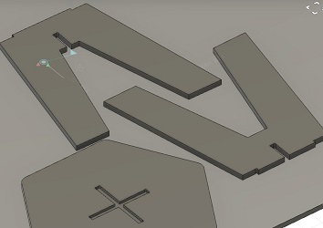
……I exported it as *dxf to open it in RhinoCam to setup the machine and get it ready for milling.
Why CAM/CNC
Keywords are: - Automation - Accuracy - Flexibility
In the Lab we have a CNC Raptor XLS .The machine is setup with a router bit that is held in the router with a collet. We are using plywood for our BIG design, but you can also use other materials like mdf, cork, hard wood or polycarbonate, acrylics, nylon, wax etc.
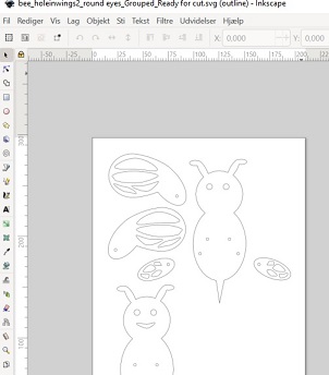
When preparing the file it is a good idea to nest the different shapes in order to optimize the use of material and the production time. I use Deepnest.io and RhinoNest for this.
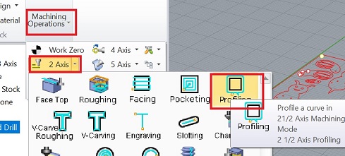
Setting things up in RhinoCam
In class we where instructed to use RhinoCam for the CNC Raptor XLS. As I had to work from home (Denmark) for this weeks assignment I used a evaluation version of both Rhino and RhinoCam. RhinoCam comes with these limitations: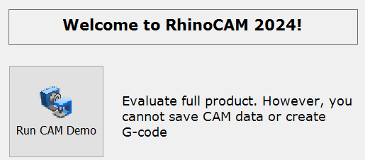
In order to learn more about the software I set up the machine and the tools for the drill and milling procedure in this version.
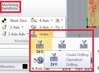
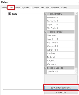
To get started there are 2 things to set up.One is drilling of the markings for the screws that hold the material down and the other is the actual milling process of the design.
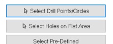
This is how I set things up for marking the drill holes: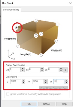
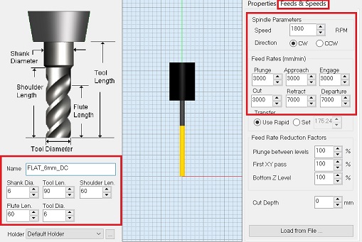 Note that the speed is 1800 RPM and cut is set to 3000
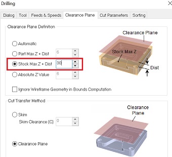 By setting this to 30 you should be on the safe side.
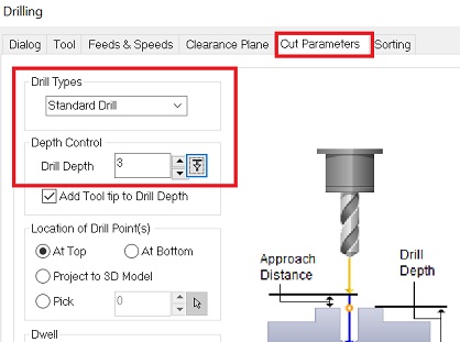 The depth is set to 3mm for every pass.
At last click “Generate”
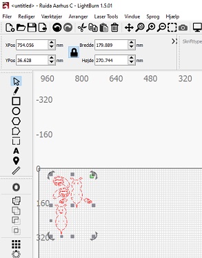
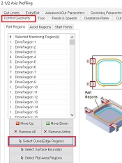 Here you select the curves or faces that you want to mill.
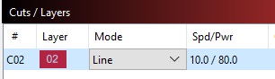
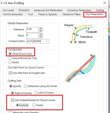 Here you set the cut direction where you can choose between upcut or downcut. I use downcut for plywood. In general you can say that upcutting is better for getting out the chips and for roughing, while downcutting is better for getting a cleaner surface finish
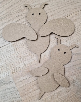
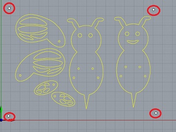
You also choose wether you want to cut on the outside or the inside of the vector.For my design I will use both cuts – outside the closed vector for the body and the wings and inside the closed vector for the eyes, the shapes in the wings and the holes in the body. I am not going to cut on the line, - but I think this possibility could be useful for engravings.
Here you set the cut direction where you can choose between upcut or downcut. I use downcut for plywood. In general you can say that upcutting is better for getting out the chips and for roughing, while downcutting is better for getting a cleaner surface finish
You also choose wether you want to cut on the outside or the inside of the vector.For my design I will use both cuts – outside the closed vector for the body and the wings and inside the closed vector for the eyes, the shapes in the wings and the holes in the body. I am not going to cut on the line, - but I think this possibility could be useful for engravings.
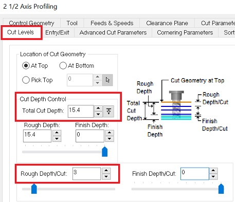 For the total cut depth I go for 15,4 as my material is 15mm and I want to make sure that it cuts all the way through.
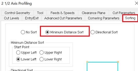
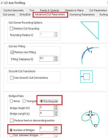 Here I choose 3 bridges/tabs and a rectangular shape.
I will continue documenting the rest of the process when I get back to the Lab
Back in the Lab I set up RhinoCam and one of the instructors looked through the G-Code together with me
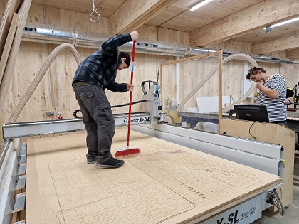
Ready for milling
First we used the broom to clean the surface of the machine
Find the right drill
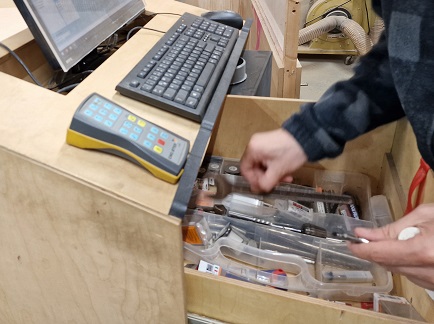
Tip: turn the drill clockwise and notice the reflection in the rotation. This one is a downcut drill.
Insert the drill with the tools for it.
Now set X,Y,Z – same as the Roland milling machine Make the drill for screws. Stop and screw down the material Set the Z axis again. Now the material is lying flat.
Fire!!
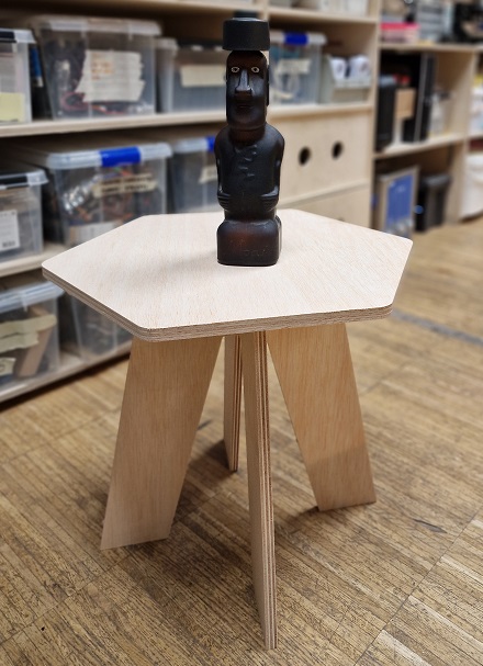
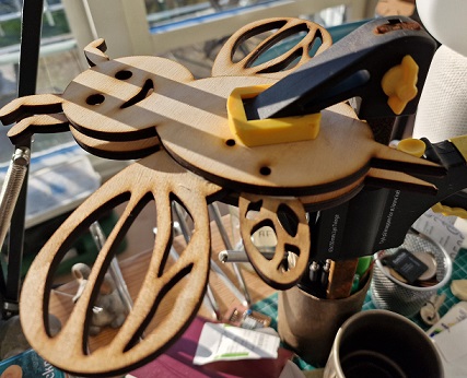
After assembly this is what the bedside table looked like