18. Project development
Research
Before starting with this project, I would like to know a bit more about drones and have some experience with flying a drone.
Drone
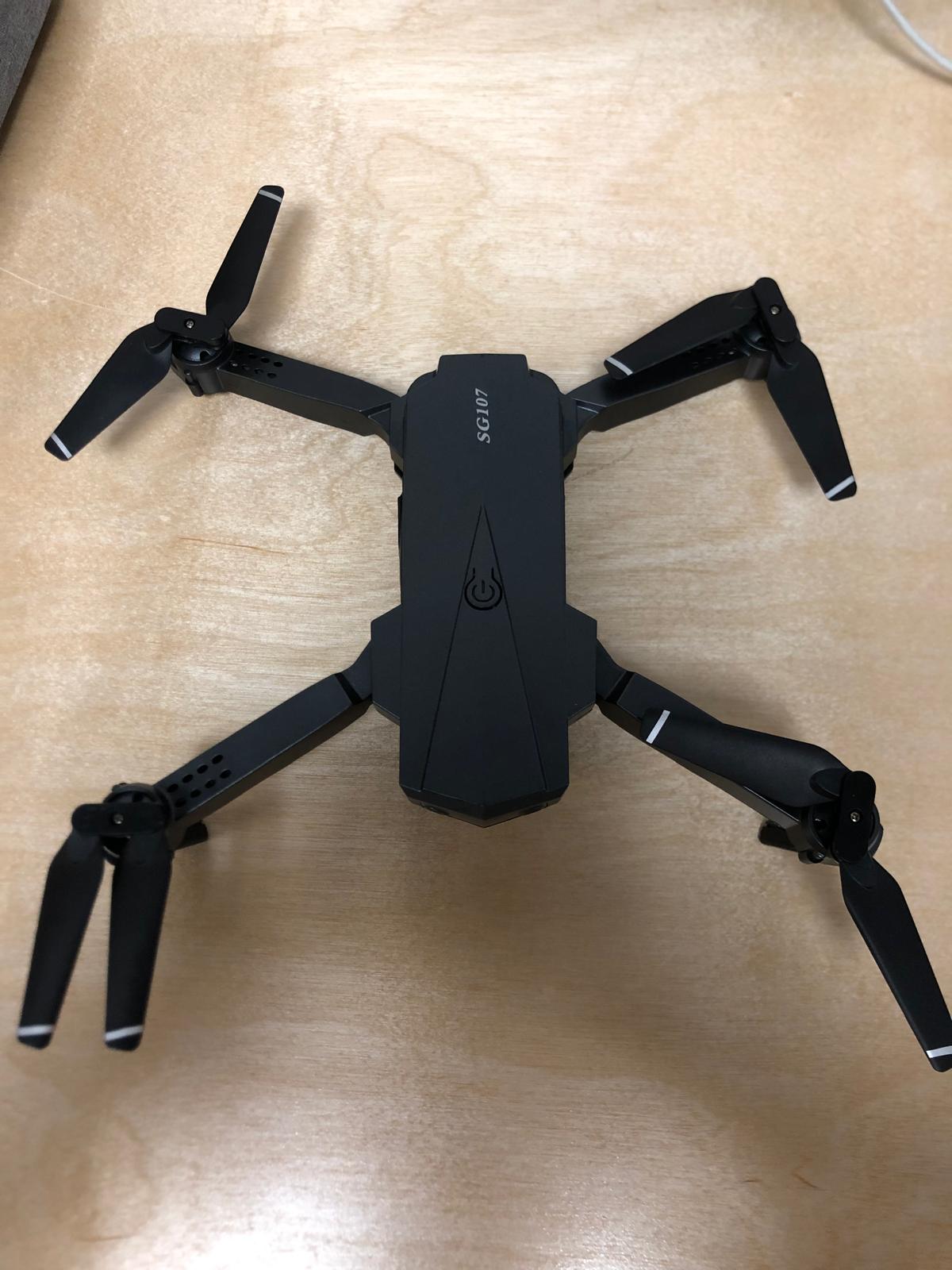
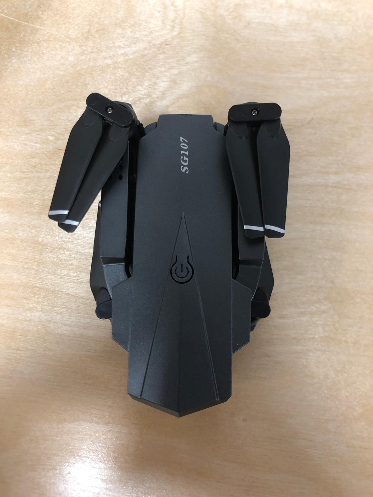
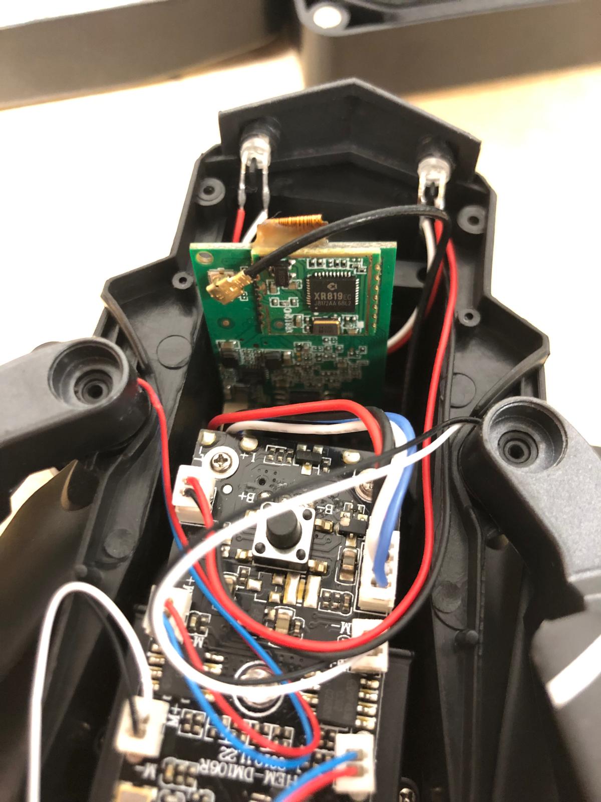
This is the type of drone I found for €50. The brand is SG107.
Batteries: 3.7V, 1200Mah: Here
Here you can see the manual of the drone.
It is quite small and lightweight so this will be a challenge to make the spraying system as light as possible.
It is possible to connect the drone with a phone. I dowloaded the app on an old iphone and got to see the cameras and can even control the drone.
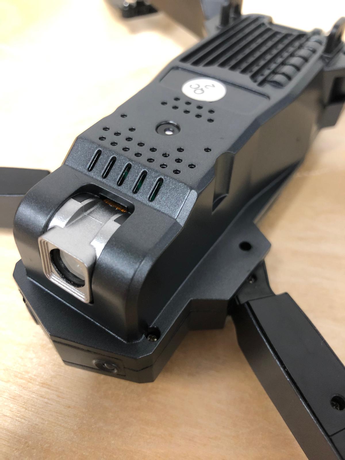
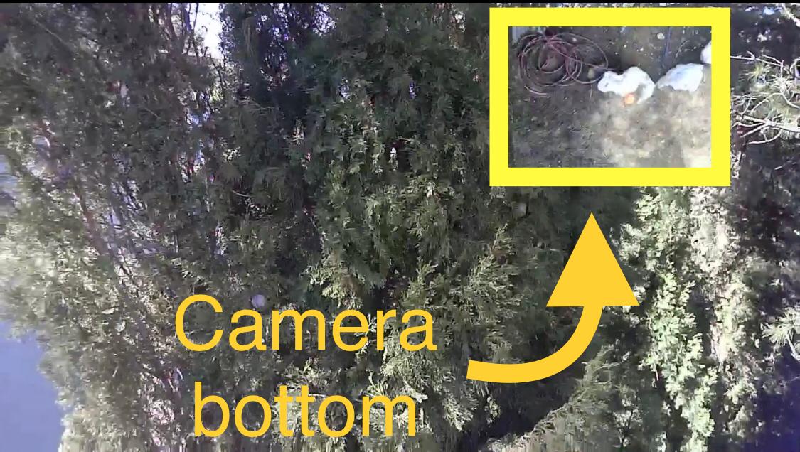
The drone has 2 integrated cameras: front of the drone + bottom.
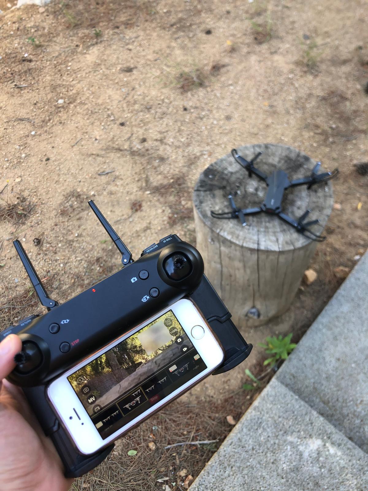
Test flight
During the weekend I tested the drone and the camera.
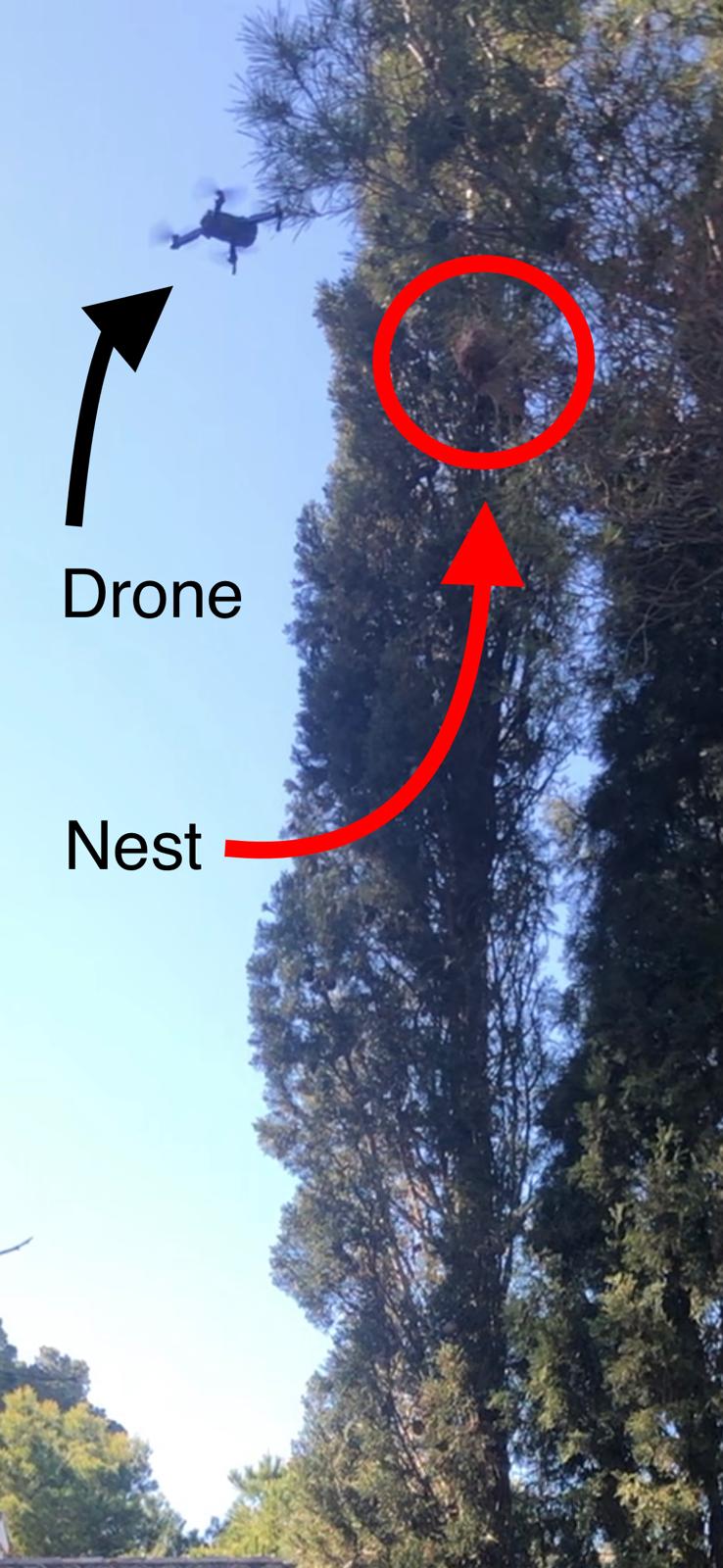
There was some wind and it was a bit challenging, the drone moves very fast. Furthermore, somethig that I have to take into account is that the needles of the pine tree are very long and "flexible". Next time i use the drone i'll check for something that can protect the propellers from the needles and branches.
I did the test to see if the drone can lift some weight. Result: it can't...
Since this drone can not lift anything i still want to keep going with the idea and in the future find myself a strong drone or create one :).
(You can see the nest in the video around sec 22.)
Sketch of the idea
To create a working drone I believe it would be best to create a small sized prototype.
Creating a drone is not that easy and requires some time and the right components so this would be something that i could when i have some time.
So to continue with this idea, I decided to buy a second hand drone and create a spraying mechanism that i can attach underneath the body of the drone.
This way I can create a mechanism that could be applied onto any other type of drone. And this would also take some time to develop and create.
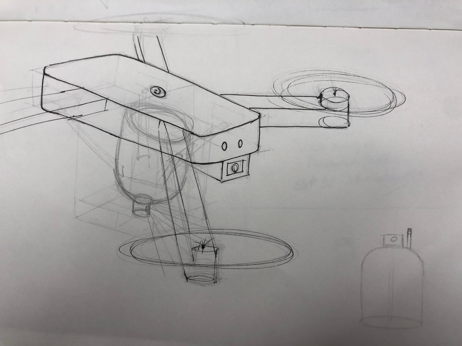
Spraying mechanism
The idea would be to have a spray attached underneath the drone that can be wireless controlled.
This spraying mechanism will be attached onto the drone with a "click" system.
Let's get started
A couple of points that i have to keep in mind: the requirements of the final project and the requirements that i have for this project.
FAB-Requirements final project
- Electronics design and production
- Design 2D and 3D
- Embedded microcontroller interfacing and programming
- Additive and substractive fabrication
- System integration
- Packaging
Personal-Requirements final project
- As simple as possible
- Minimize components
- Make it as light as possible
- Use existing products
- Universal application = works with all types of drones
- Easy to dis-assemble
Electronics design and production
For this project, i will need 2 pcb's that communicate with each other: the remote and the spray mechanism.
Microcontroller
The type of microcontroller i'd like to use is the ESP32c3 or ESP32s3wroom1
These are the datasheets:
ESP32c3: datasheet
ESP32S3: datasheet
I decided to use the ESP32 S3 WROOM 1 because this microcontroller is easy to program and has been used before in the assignments.
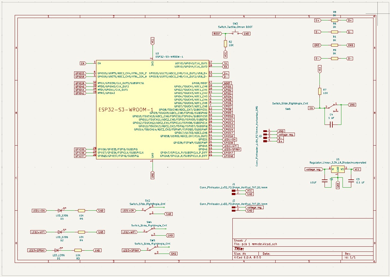
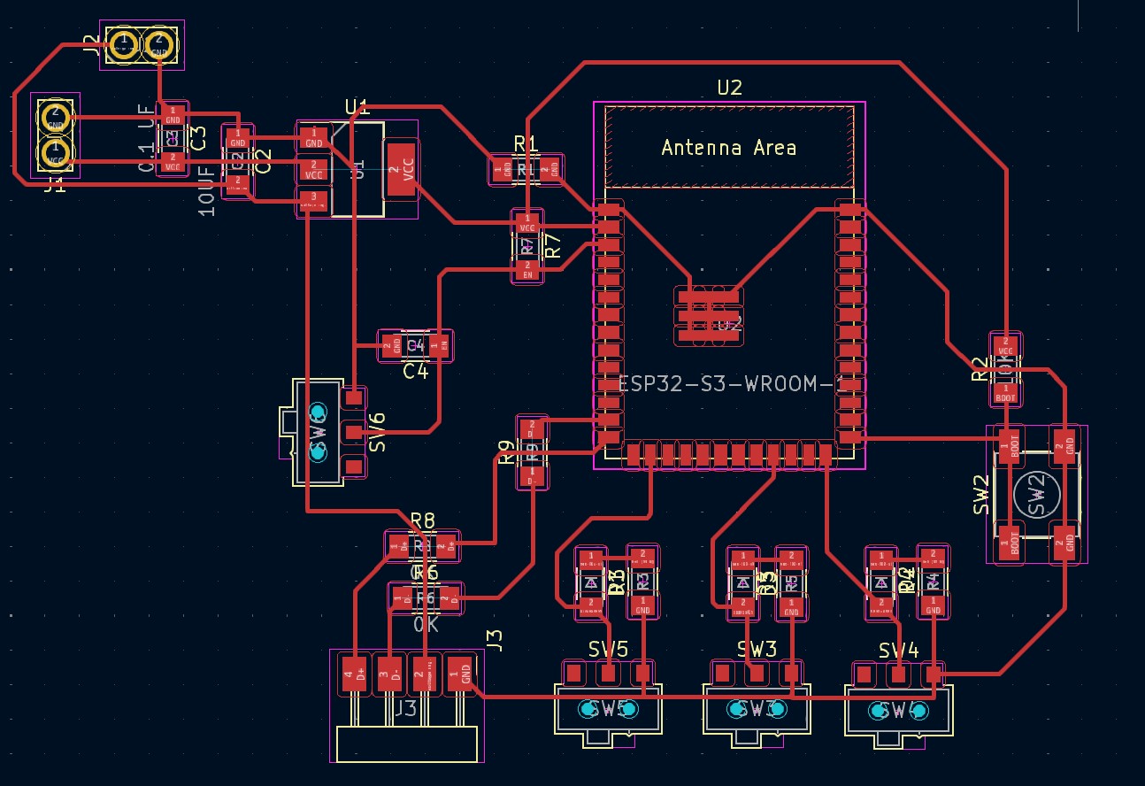
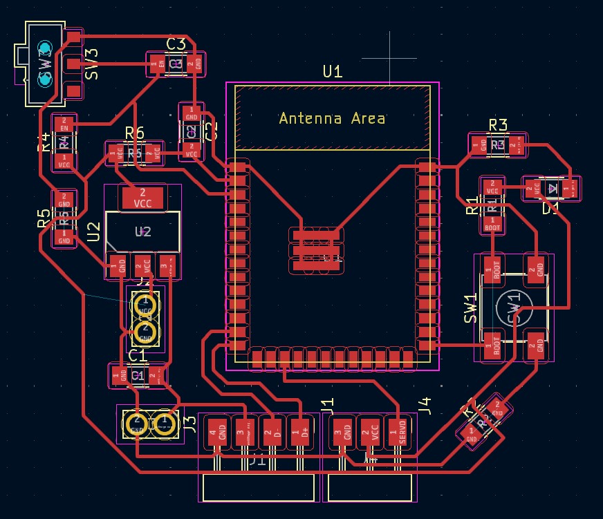
PCB design: remote
For the remote i made a list of everything that i would need: microcontroller, capacitors, resistors, voltage regulator, reset and boot button, led's, switches and the usb to program the microcontroller. I haven't decided yet which power source i will be using so i created 2 different paths for the power source.
This is the design in kicad of the pcb schematic and layout.
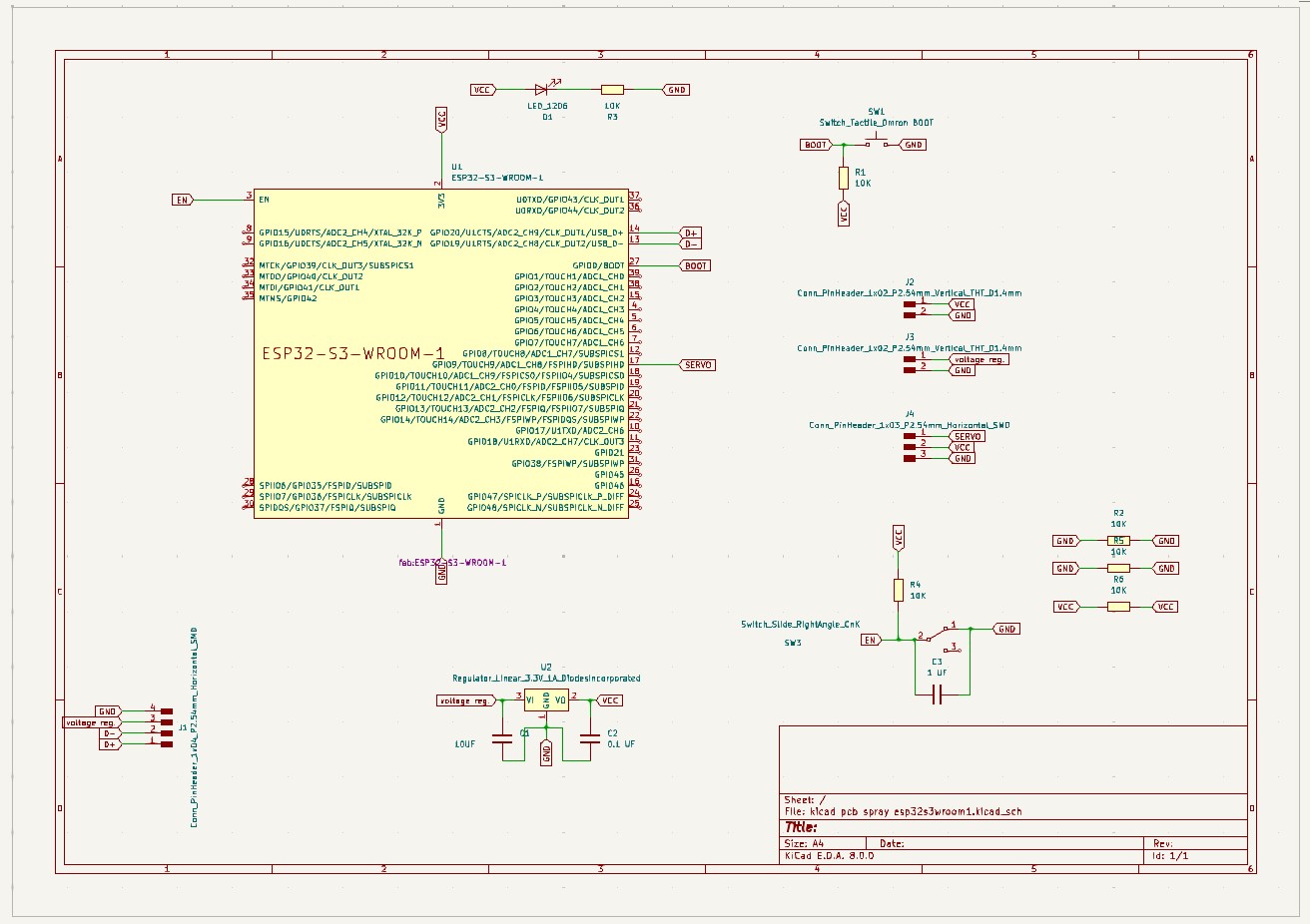
PCB design: spray mechanism
For the spray mecyanism i also made a list of everything that i would need: microcontroller, capacitors, resistors, voltage regulator, reset and boot button, power led, 1 switch and the usb to program the microcontroller. As the spray mechanism will be attached to the servo motor, i will need at least 1 pin to attach it to. The power source will be a battery (still have to decide which one).
Pcb production
After exporting and creating the png files, I created the .rml files for the SRM-20 milling machine.
You can find all the files here:
files
Embedded microcontroller interfacing and programming
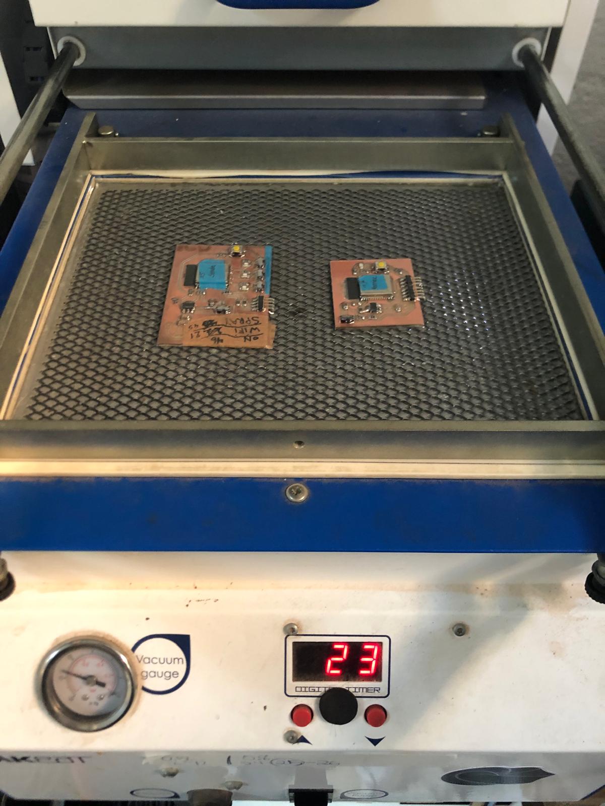
Testing the boards and programming them
The first test i did when i finished soldering the boards, was connecting it to my computer and see if they get recognized as a device.
It happend sometimes that my boards were not recognized as a device. This meant that something on my board was wrong or badly soldered. Most of the time it was because of a bad connection or a GND trace that was not fully drawn. This was a good learning process to understand what went wrong and how to fix it.
My boards need to communicate. I chose the ESP Now protocol to let them communicate. "ESP-NOW is a wireless communication protocol developed by Espressif for their ESP8266 and ESP32 microcontrollers, allowing for low-latency, low-power, and peer-to-peer data transmission without the need for a Wi-Fi network. It uses a proprietary, lightweight protocol to send small data packets directly between devices, making it ideal for IoT applications requiring quick and efficient data exchanges."-when you ask chatgpt to describe it in 2 sentences. :p
This website explain it step by step hwo to use the ESP NOW protocol: website
With this protocol, I'll need to know the Mac addresses.
Action-Reaction: when the switch is pressed on the board of the sender, the receiver needs to activate the servo and turn it 90degrees. Furthermore, the sender also needs to constantly check if the receiver is connected. If there is a connection, the red led has to turn on. If it is disconnected, the led has to turn off.
Finding the MAC Address
A mac address is a unique address you need, to identify each board to send data to. Every board has a unique mac address.
To know the mac address, you need to load this code and read the serial. This will give a 12 digit long code with numbers and letters.
          #include
          #include

            void readMacAddress(){
              uint8_t baseMac[6];
              esp_err_t ret = esp_wifi_get_mac(WIFI_IF_STA, baseMac);
              if (ret == ESP_OK) {
                Serial.printf("%02x:%02x:%02x:%02x:%02x:%02x\n",
                              baseMac[0], baseMac[1], baseMac[2],
                              baseMac[3], baseMac[4], baseMac[5]);
              } else {
                Serial.println("Failed to read MAC address");
              }
            }

            void setup(){
              Serial.begin(115200);

              WiFi.mode(WIFI_STA);
              WiFi.STA.begin();

              Serial.print("[DEFAULT] ESP32 Board MAC Address: ");
              readMacAddress();
            }

            void loop(){

            }
Programming the remote = sender
To test the ESP32 S3 WROOM 1 that I have as the microcontroller on the remote pcb, I decided to use the dev board i made in week 6 as a peer. This one also has the same microcontroller.
The remote PCB weighs 24gr
This is the code for the sender:
Programming the spray mechanism = receiver
To test the board, I used the remote board as a peer. These two will have to communicate so this was an important step!
The spray PCB weighs 18gr
This is the code for the receiver:
Test with servo motor
To be able to move anything, a servo motor would be the best choice. This is a very lightweighted component and has a high torque.
The first test would be to connect the servo motor to my board and make it work.
The second test would be to make the servo motor move using the second microcontroller that is connected via ESP now protocol. In this case, the sender will send the signal to the receiver to move the servo.
The servo motor weighs 20gr
Video of the progress
To visualize the past steps, you can see it all in the video below!
The arduino running in the background with the serial monitor reading on both boards and the servo turning on and off.
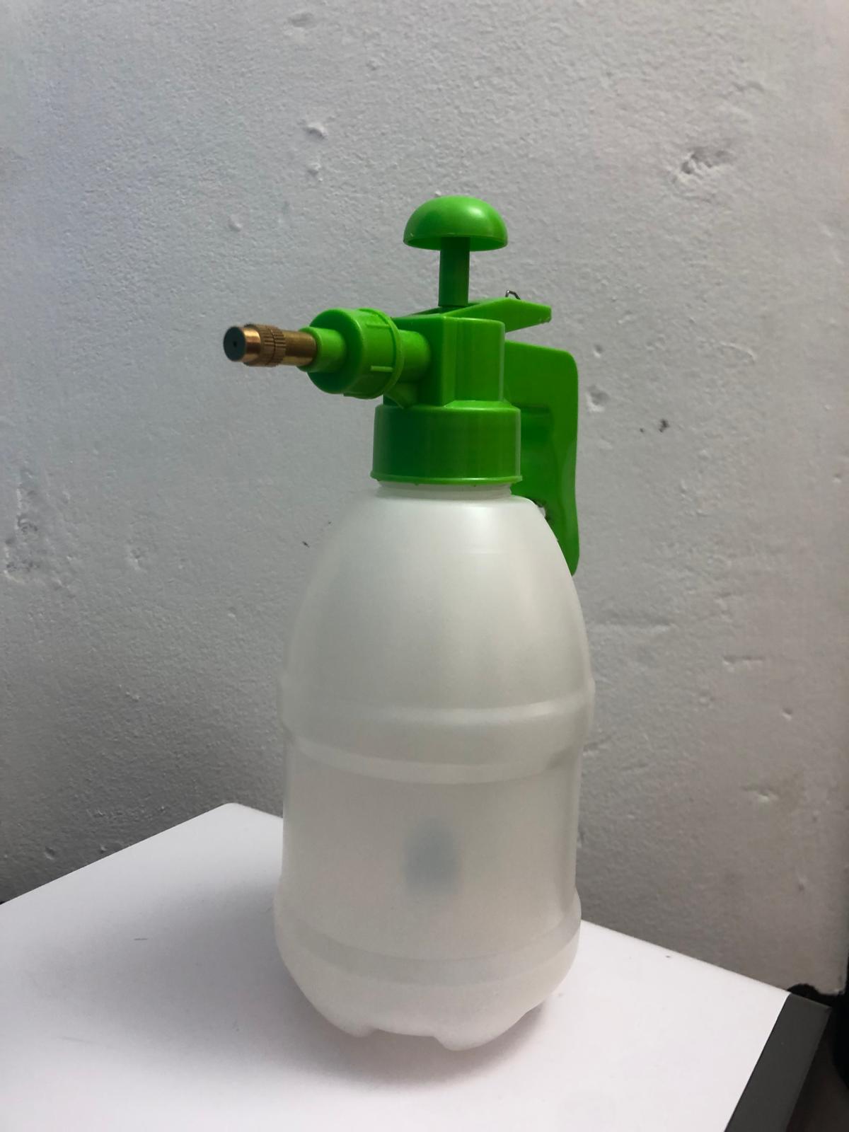
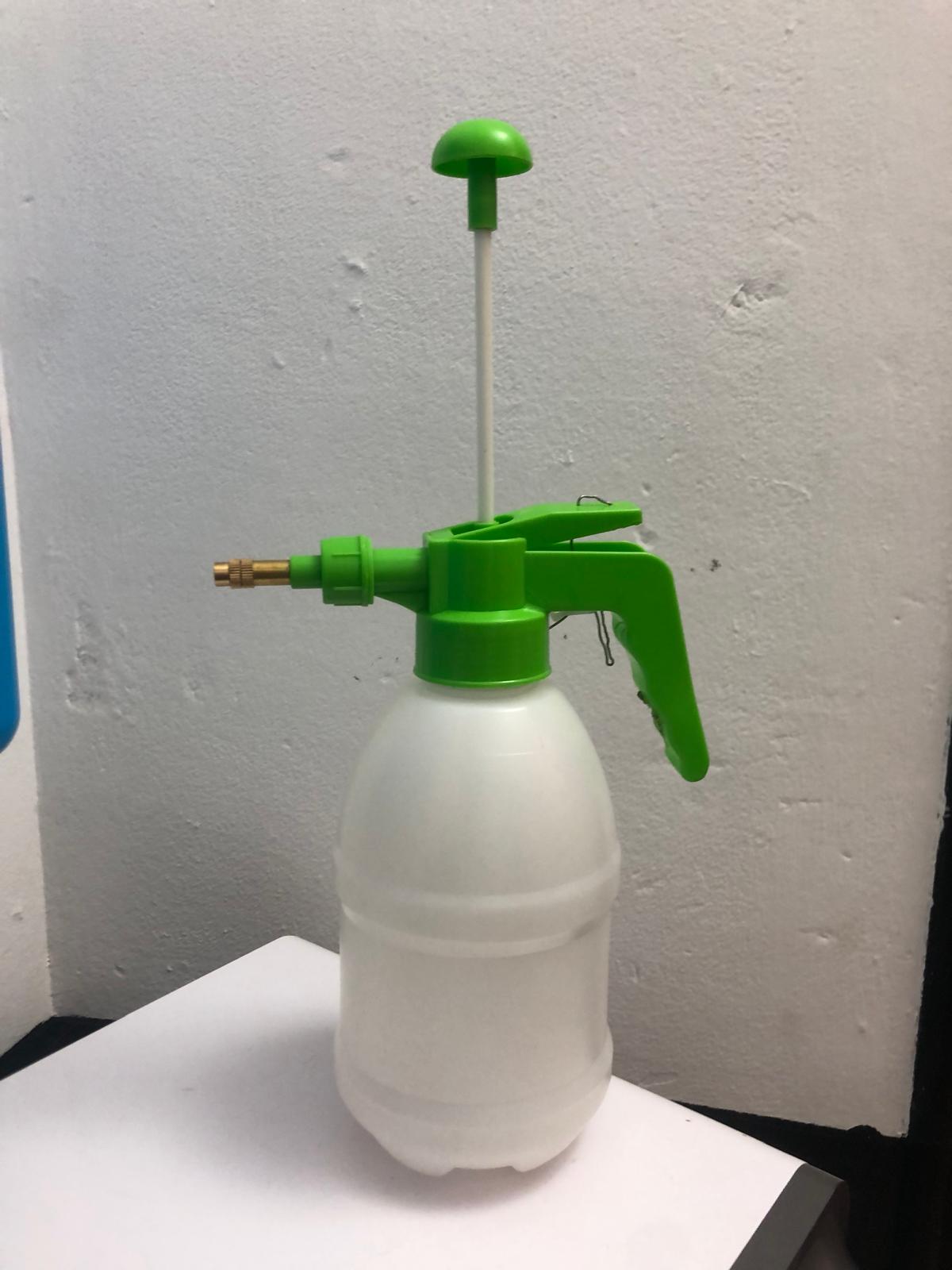
Test with the spray+container
The type of spray that i need is a spray that sprays continuously. This means that the spray needs to be similar as a spray paint can.
The spray paint can works with aerosols and is not made to refill.
The other type of spray that works with pressure and can be refilled, is the one that is used in gardens.
I found this spray in the garden store and it exists in bigger formats too.
(I forgot to take a picture before changing anything but it still looks the same)
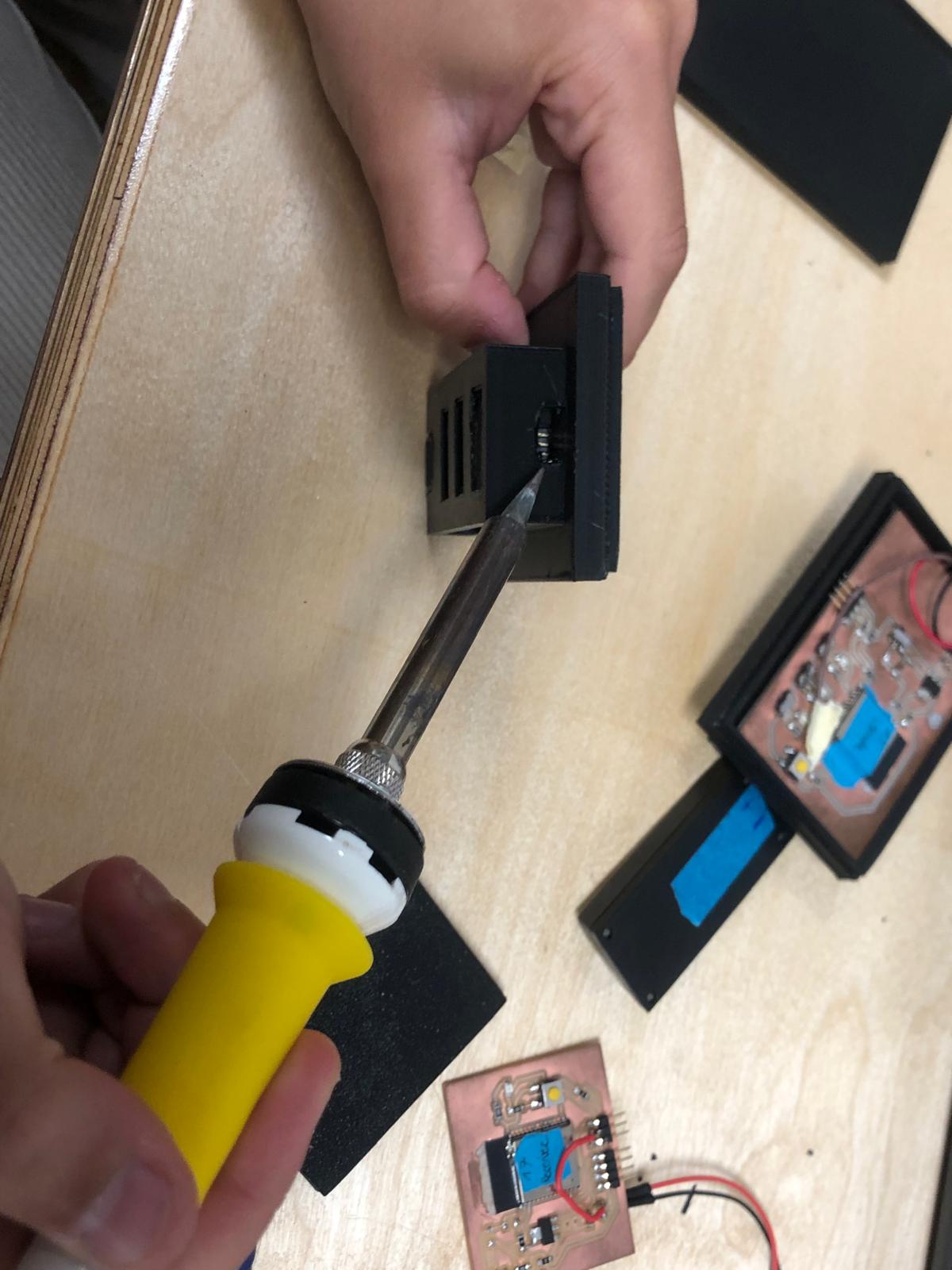
I attached the servo onto the spray by melting the plastic of the spray handle. I used an old soldering iron to do this. Using this technique makes it possible to add something onto the spray without needing glue and gives the space to freeform the needed shape.
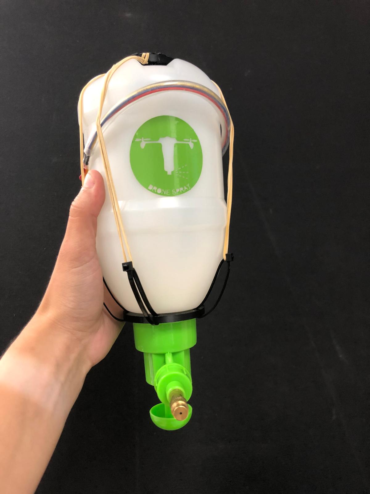
The spray/ pulverizer weighs 179 gr
Video test
In the video below you can see the 2 boards communicating with the servo attached onto the spray.
Power source
The drone uses a small battery that can be recharged with a usb cable. There are 2 spare batteries that I would like to use to power the 2 pcb's.
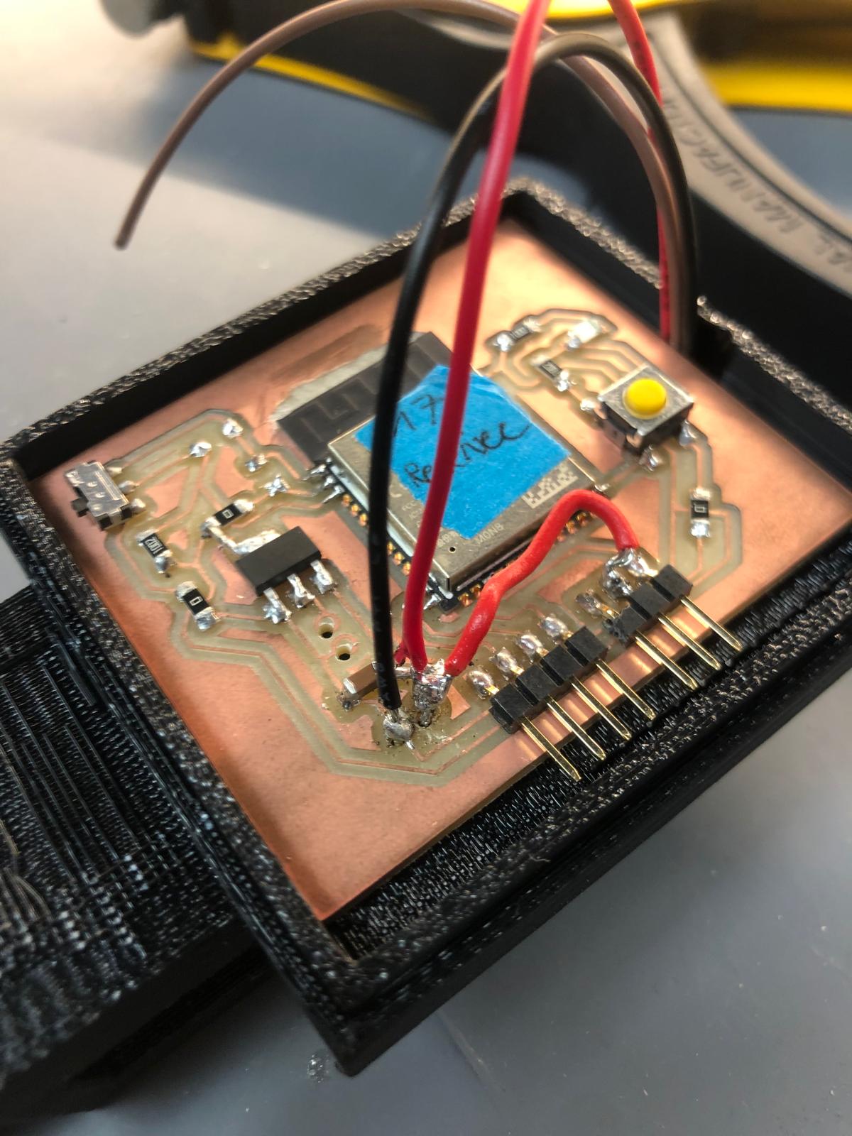
To be able to use these batteries, I have to know the pinout of the battery. There are 3 pins: vcc, ground and a third one for bms (battery management system).
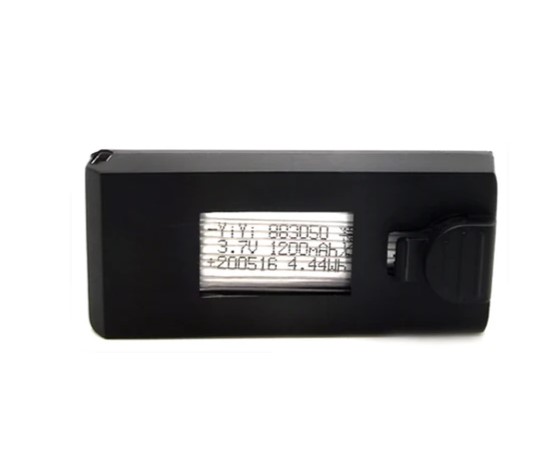
The batteries have the correct voltage and can power the boards and the servo.
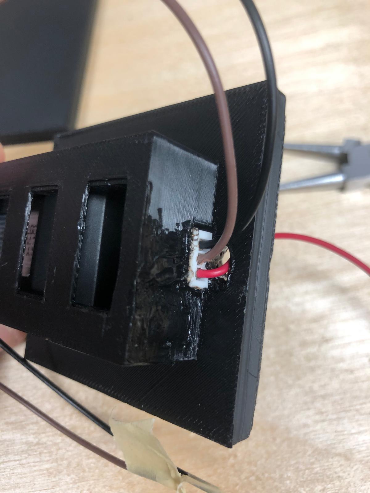
On the spray board, I used a jumpcable to connect the vcc from the battery directly with the vcc of the servo. This way the servo receives a higher voltage and can be more powerful.
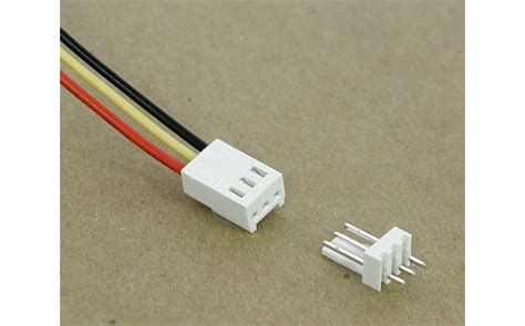
The batteries have a component that connects with 3 pins. Unfortunaly, i can't find such components so i'll have to be creative and find something!
To fix this connection, i found these special cables that you can see in the picture below.
Packaging: Additive manufacturing
Now that everything works, it is time to think about the packaging and how to mount everything.
The challenge is to keep it as light as possible. I checked the different possibilities of fabrication. 3D printing in PLA or ABS will be the most convenient way to create a waterproof, lightweight and custom packaging.
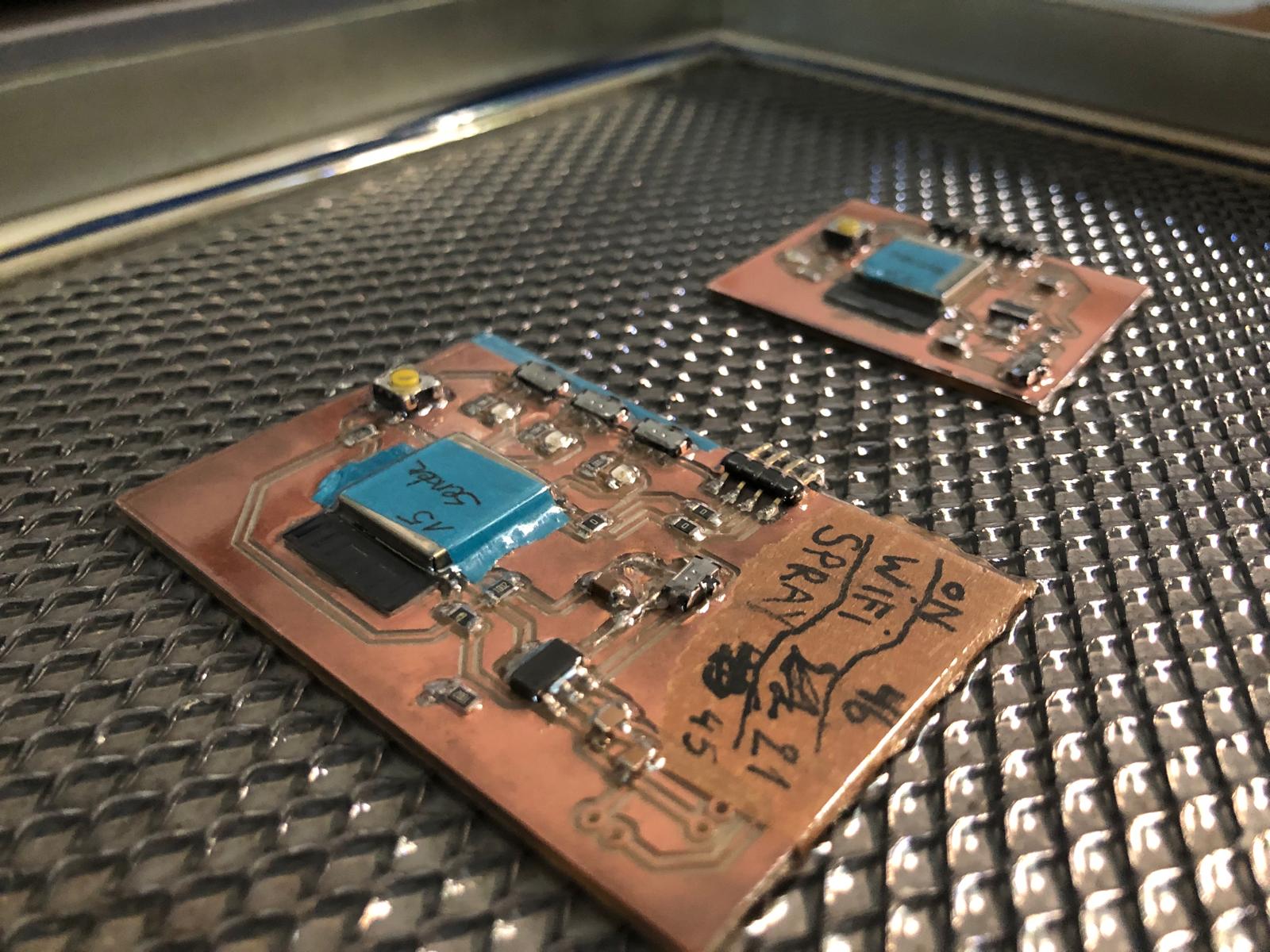
Thermoforming with PETG and 3D printing with PLA could be a nice combination as packaging. That way it is lightweighted, you can see the pcb (that's always nice to see) and you can thermoform on top of the pcb (with some needed protection for some components).
The thermoforming looks like this:
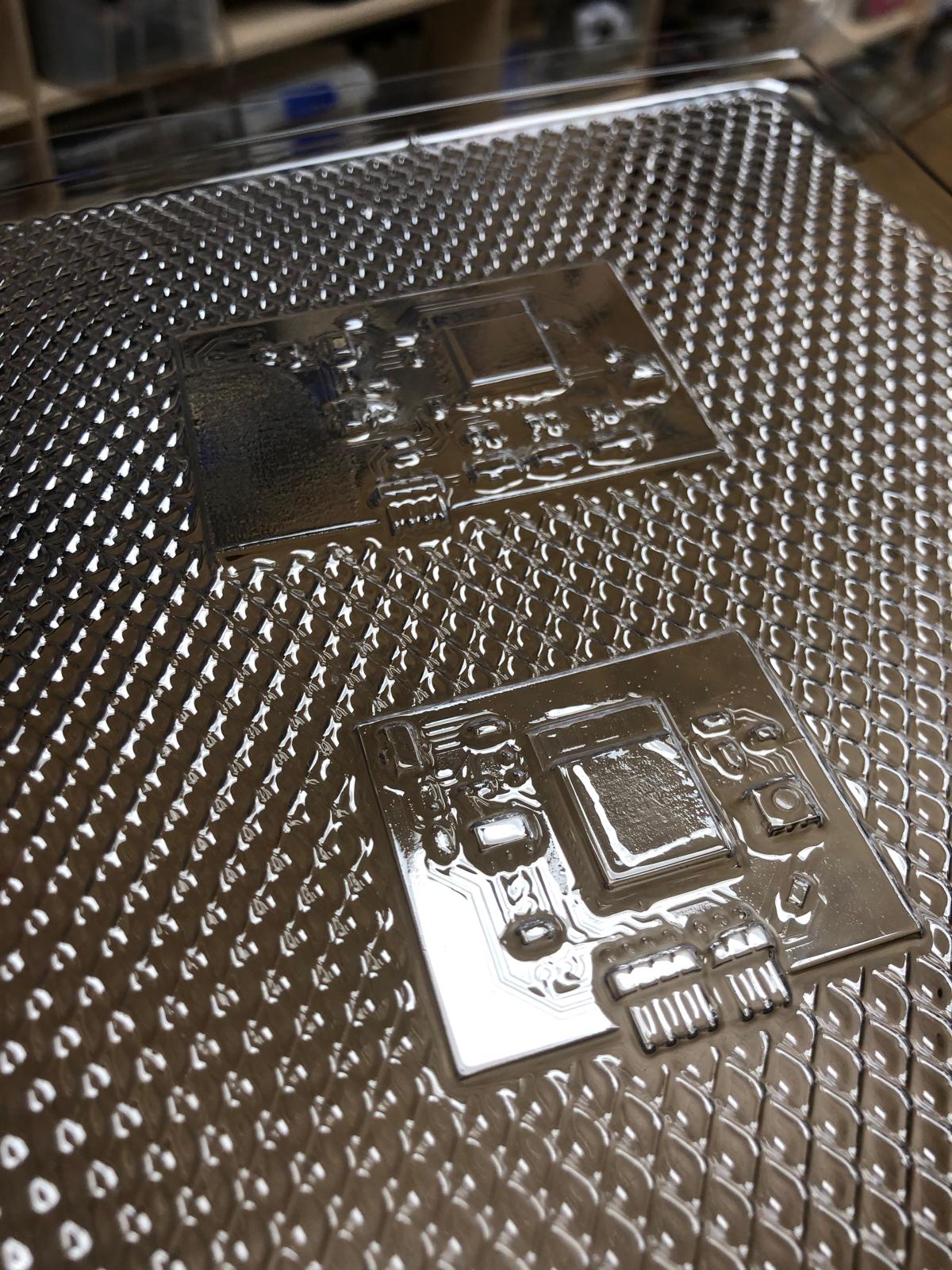
These are thefiles
Remote and spray case
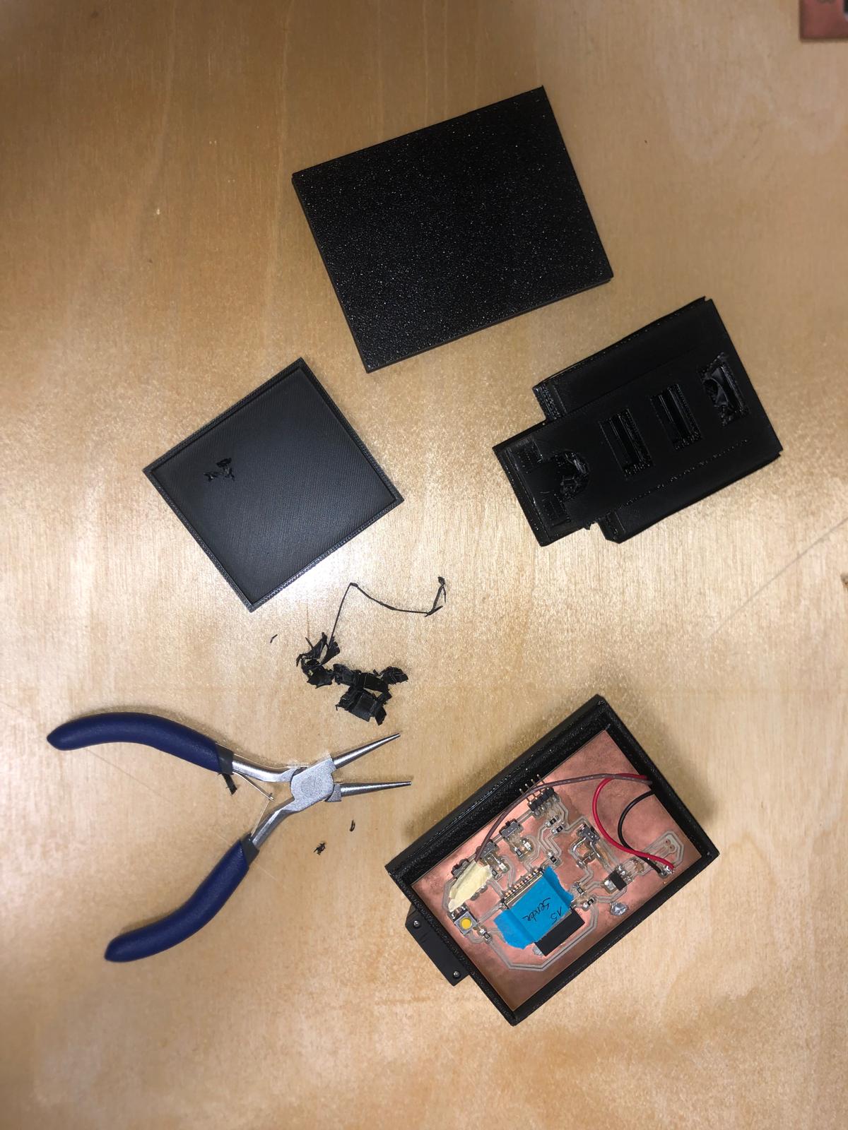
To make sure that it is all waterproof, I decided to firstly create a closed case that i can 3D print. The first test I did was the battery casing. The battery needs to fit perfectly and slide into the 3 connecting pins.
What I need in the case for the remote is the switch, 3 led's and the battery.
The spray case need the battery, 1 led and an opening for the connection of the servo cables.
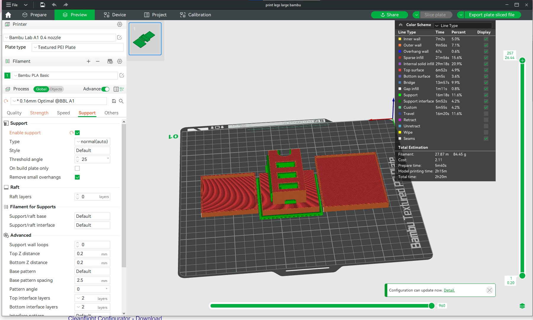
You can see the 3D prints in the picture below and the support that was needed.
In the second picture you can see how i created the holes in the case where the cables for the battery go through.
video assembly cases with battery
In the video below you can see how the battery slides into the case and connects to the pcb
Packaging: Substractive manufacturing
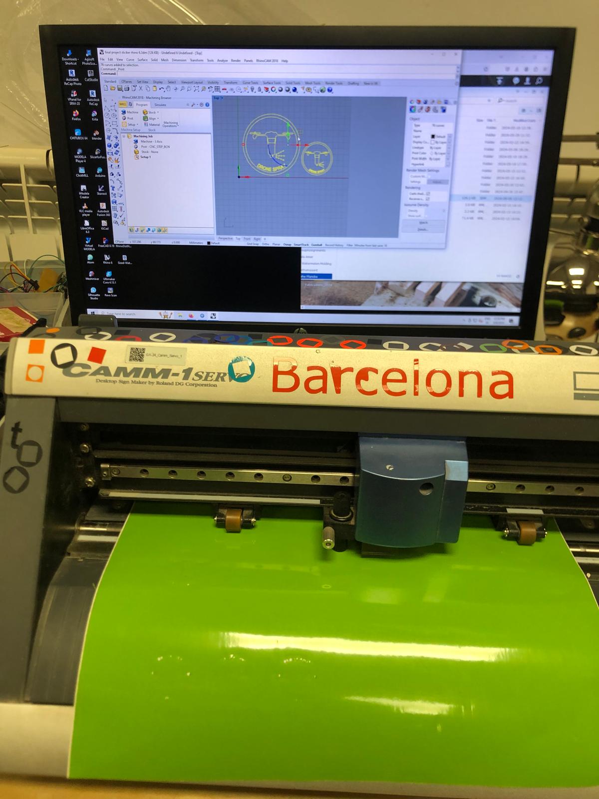
For this production method, I decided to make a sticker to put onto the bottle. Unfortunatly, I made this after shooting the video.
Here you can see the process: create the file in rhino, send it to print, connect and setup the vinylcutter, and ... cut! Once it's cut, I put it onto the bottle!
Fortunatly, there was a bright green vinyl to cut from, just like the color of the bottle :) .
System integration: Click system to attach the spray underneath the drone
I have been using quadlockfor a while and this works with a good slide & click system. I thought that it could be nice to use to attach the bottle onto the drone.
I recreated the quadlock system in rhino and added it to another part that i designed.