Week 04 - Electronics production
Group assignment: PBC production
On the link below you can find the complete process of this week's group assignment, covering machine usage and setting up parameters for PCB milling. Click here
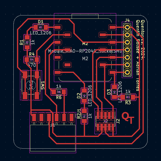
Quentorres PCB board
Instructions
Customize board
I added my initials on the lower left corner of the png file by Quentorres using Adobe Illustrator. I noticed that I had to separate each letter from the other because once I runned the png on Modsproject the offset would distort the contour of the letters. What I didn't consider for later was the position regarding the space of the physical board and the outline cut. Noted for next milling!
 (1).png)
 (1).png)
 (1).png)
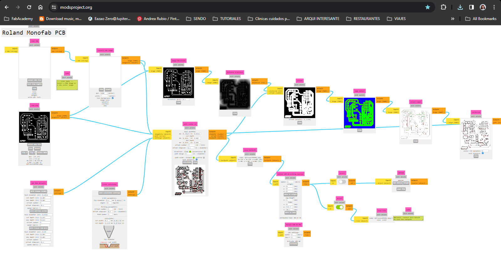
Modsproject parameters
PNG and machine settings
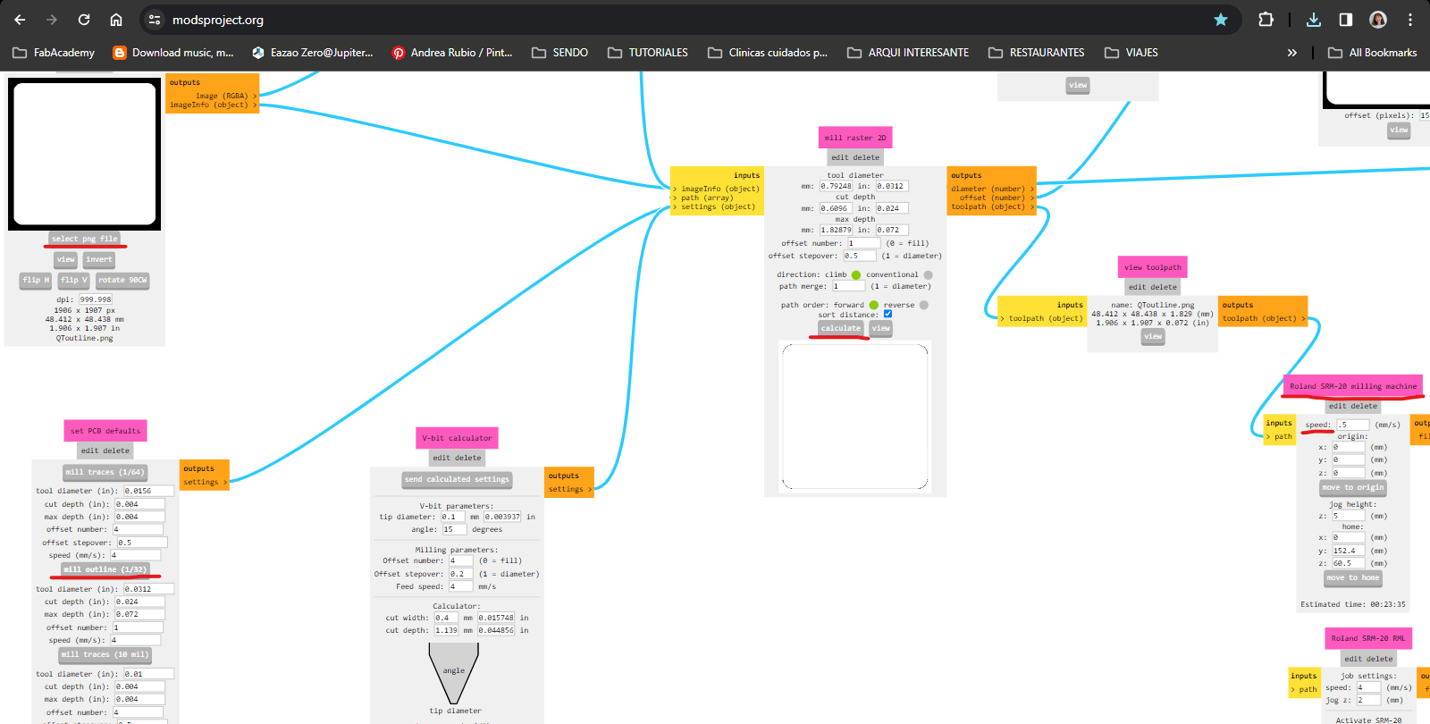
1. Open modsproject.org / right click anywhere / select programms / look for SRM-20 milling / select "mill 2D PCB".
2. Upload the tracing file that was customized.
3. Select from the box below the option mil traces (1/64), we begin with the smallest bit to trace our design.
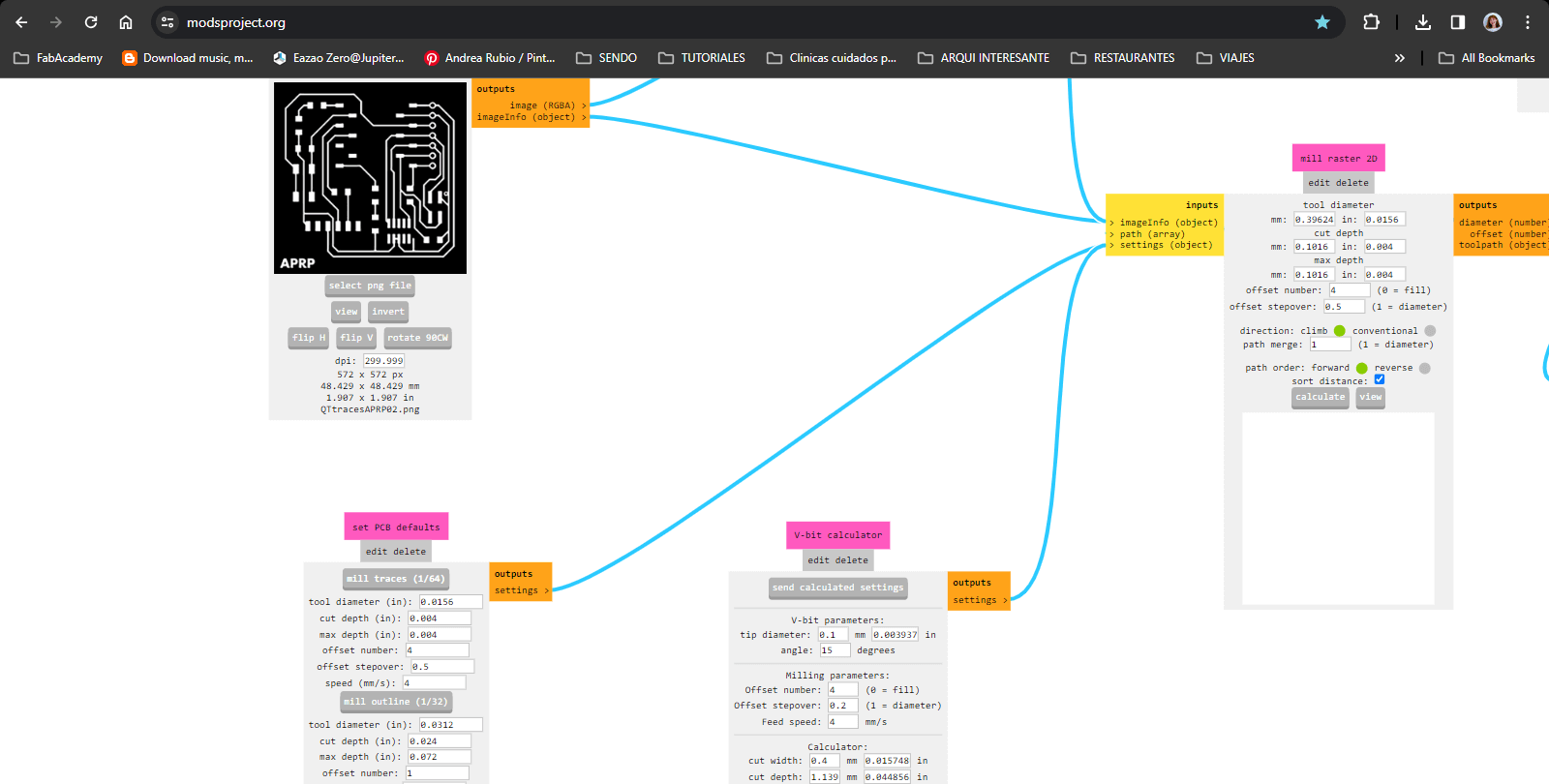
4. On the "Roland SRM-20 milling machine" box we change the following settings according to the 1/64 bit:
- - Speed: 3 mm/s
- - Origin: x,y,z = 0
- - Jog height: 5 mm (elevation of the bit each time it moves)
- - Home (z): keet high just for safety of the bit
5. On the "mill raster 2D" box, change the offset number to 4 as a default and safety tracing. This number could vary from 3 or 4.
6. Press "Calculate" to generate a preview and automatic download of the machine's tracing path. See preview (blue lines).
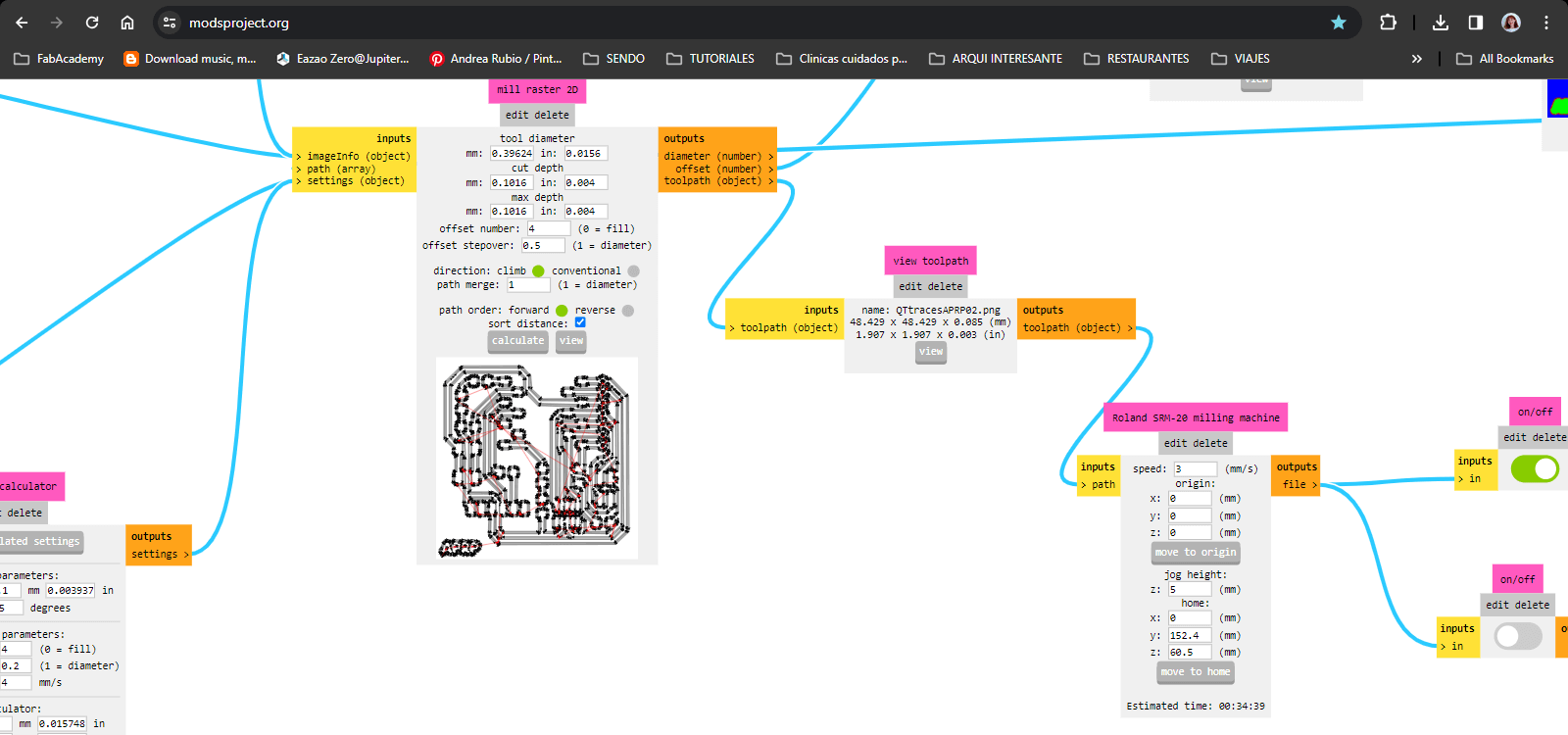
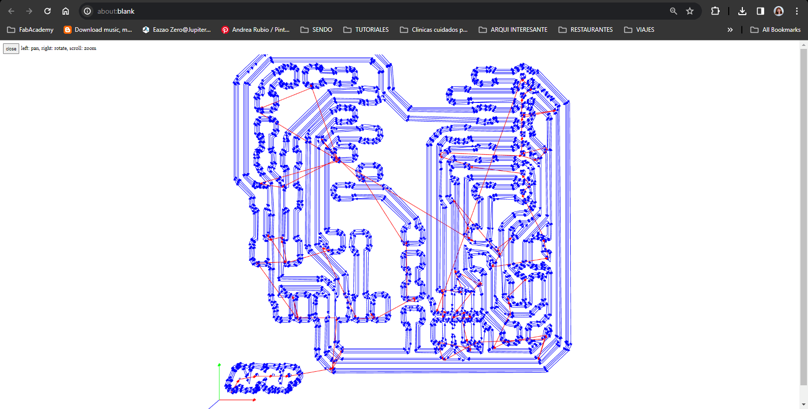
Overview of the tracing file: you can check how the PNG file is being read by the machine on the upper boxes. Each time you want to make a change and re-download, just keep pressing "calculate" until you finish your settings. Watch out for all the downloads on the background, carefully select the final file!
Holes & Outline
7. Upload first the holes png file
8. Select from the box below the option mil outline (1/32), we continue with the bigger bit to do the final cut of the board.
9. On the "Roland SRM-20 milling machine" box we change the following settings according to the 1/32 bit:
- - Speed: .5 mm/s (we need to lower the speed to avoid pushing the bit and breaking it)
10. Press "Calculate" to generate the preview and new file for making the holes.
11. Repeat steps 7 to 10 for the outline file.
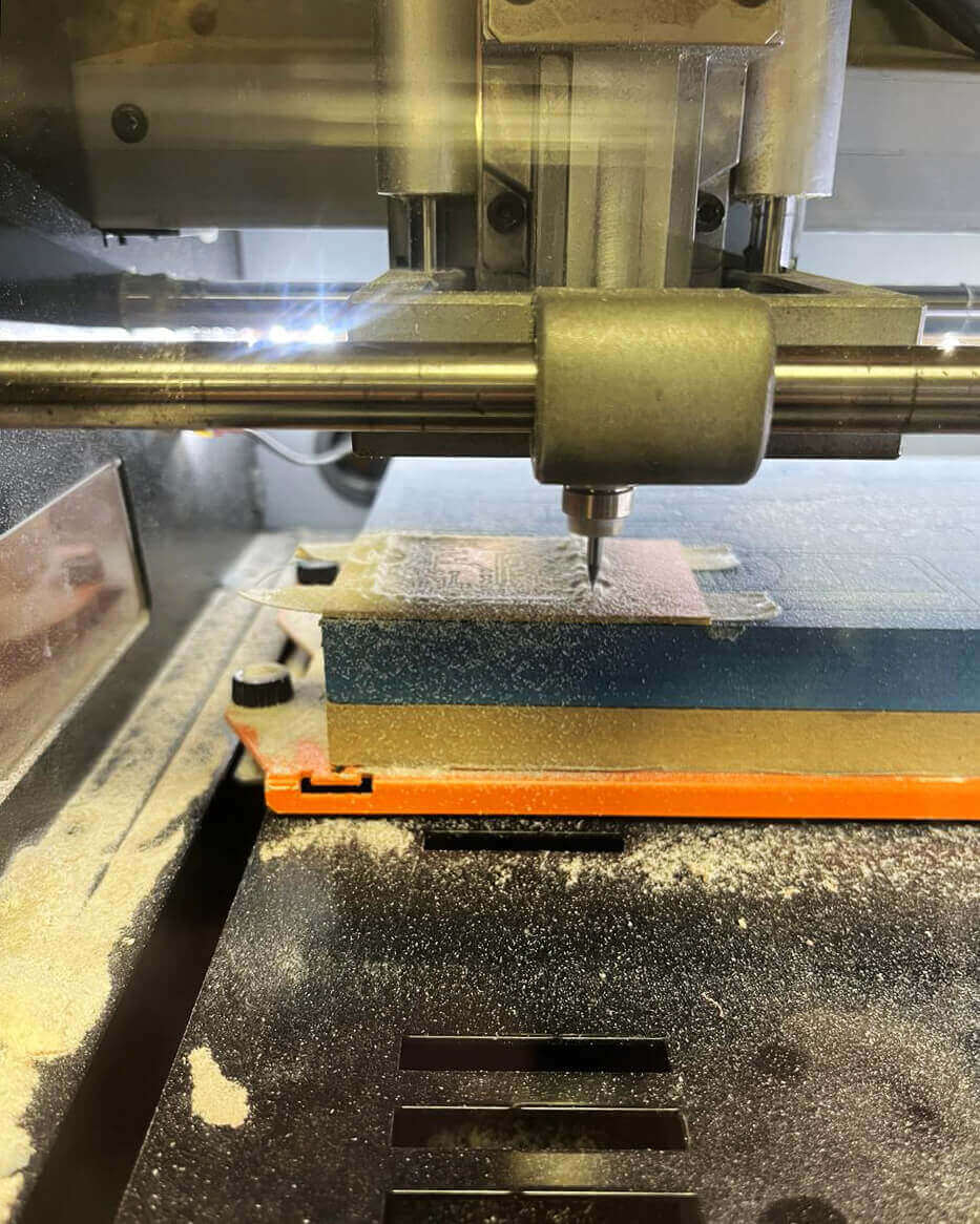
Hands on Roland SRM-20 milling machine
Setting PBC board & milling bits
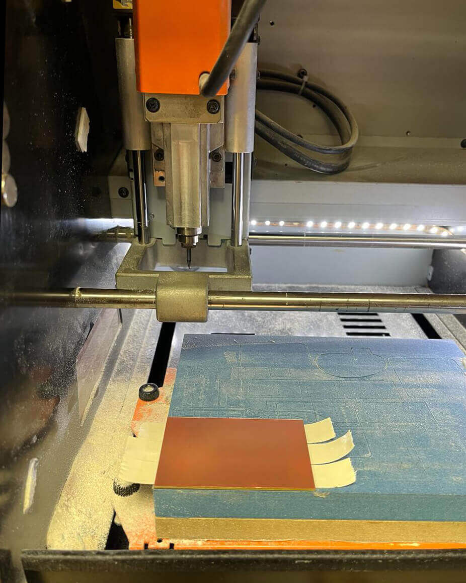
1. [First image - left] Grab PCB and apply double side tape on the non-copper face. Leave extra space for peeling the side and not affect the base leveling.
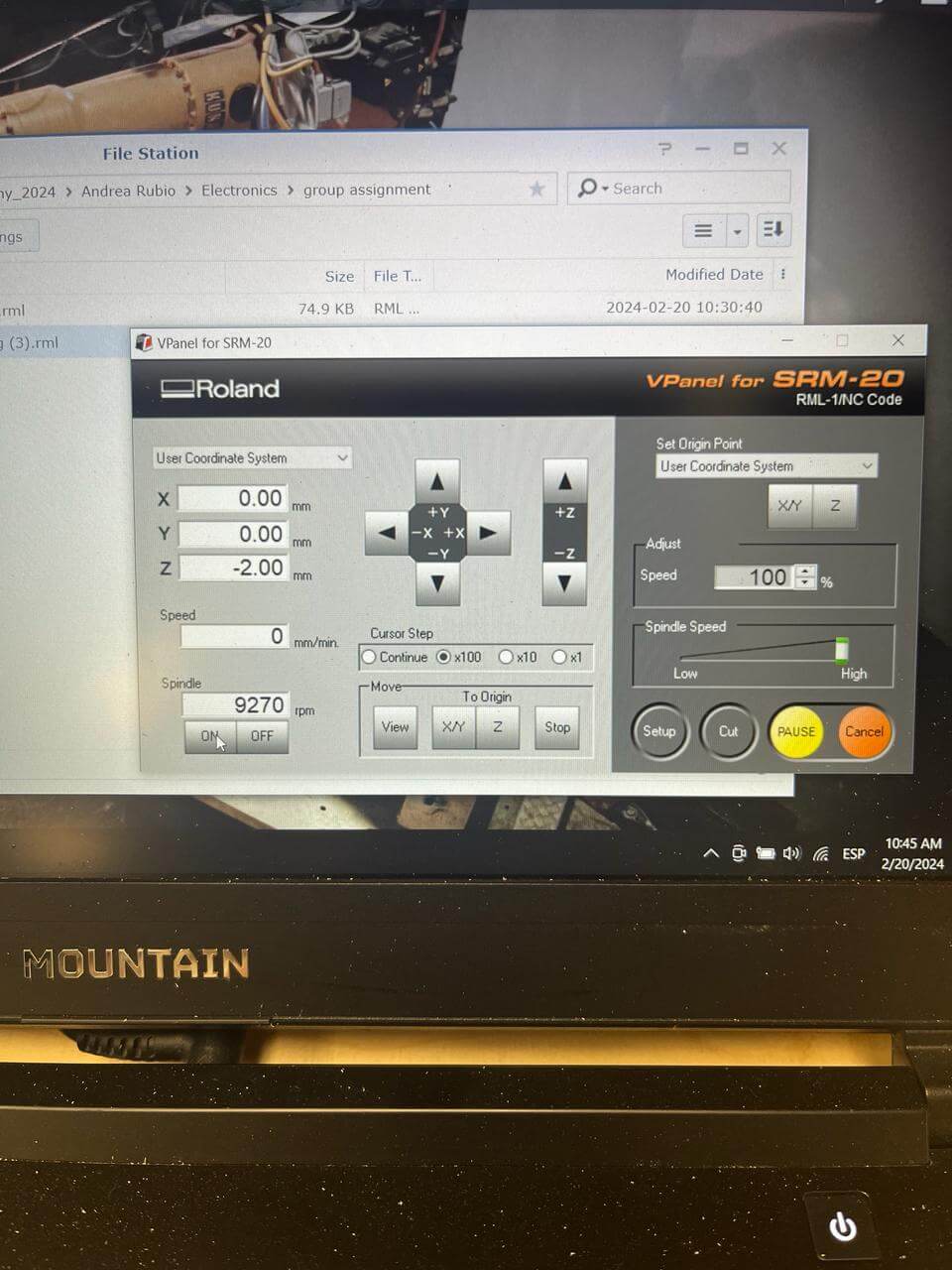
2. [Second image - left] Open software / Set XY and Z using up/down/right/left keys until it's leveled.
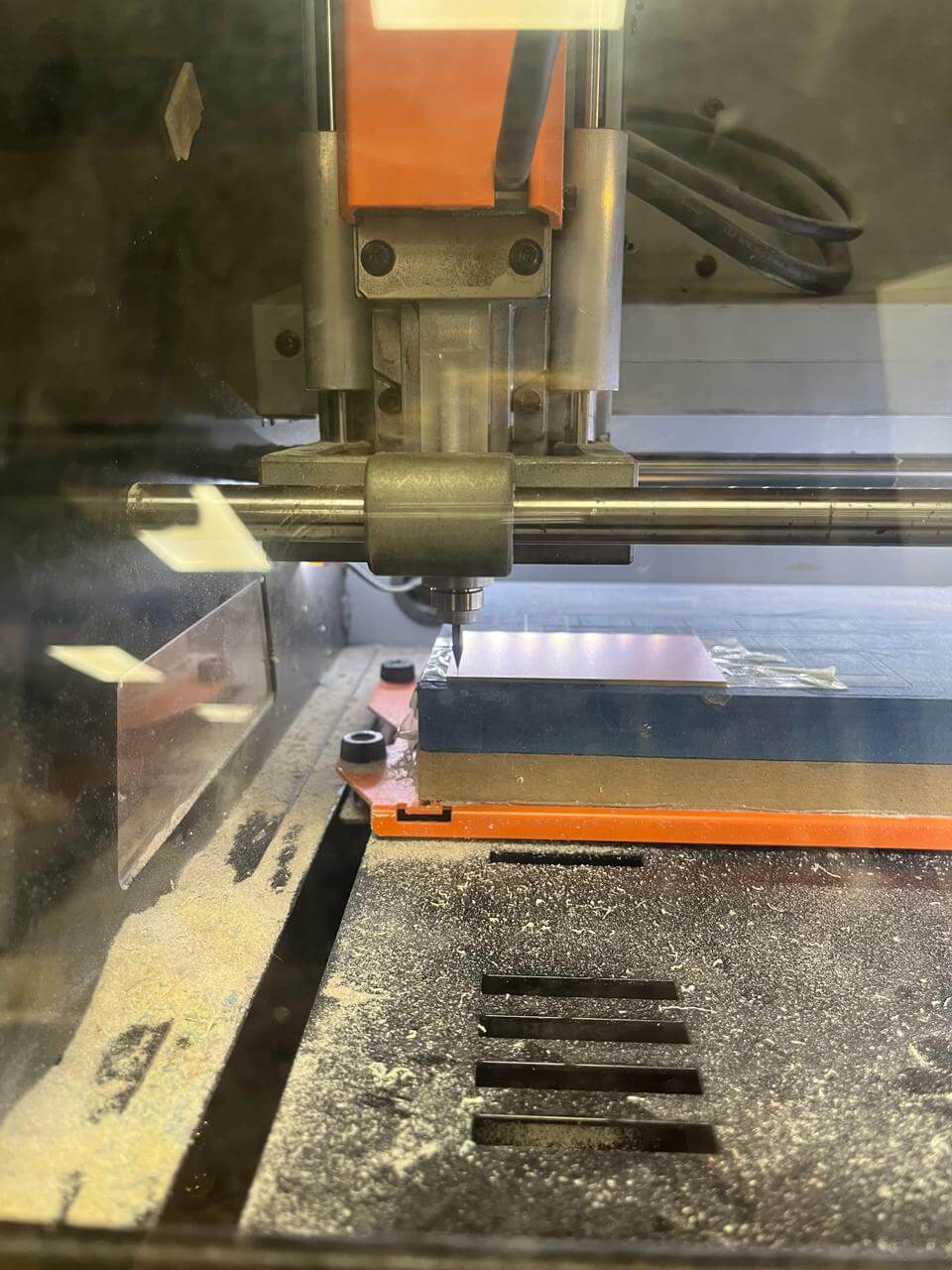
3. [Third image - right] Change bit to 1/64 since we are starting with the tracing file / Set Z carefully dropping the bit so it touches the board.
***IMPORTANT: Make a spindle test to ensure the bit is leveled and avoid missed cuts.
4. [Fourth image - right] On the software, select "Cut" and add the tracing file / press "Output" to start.
***IMPORTANT***
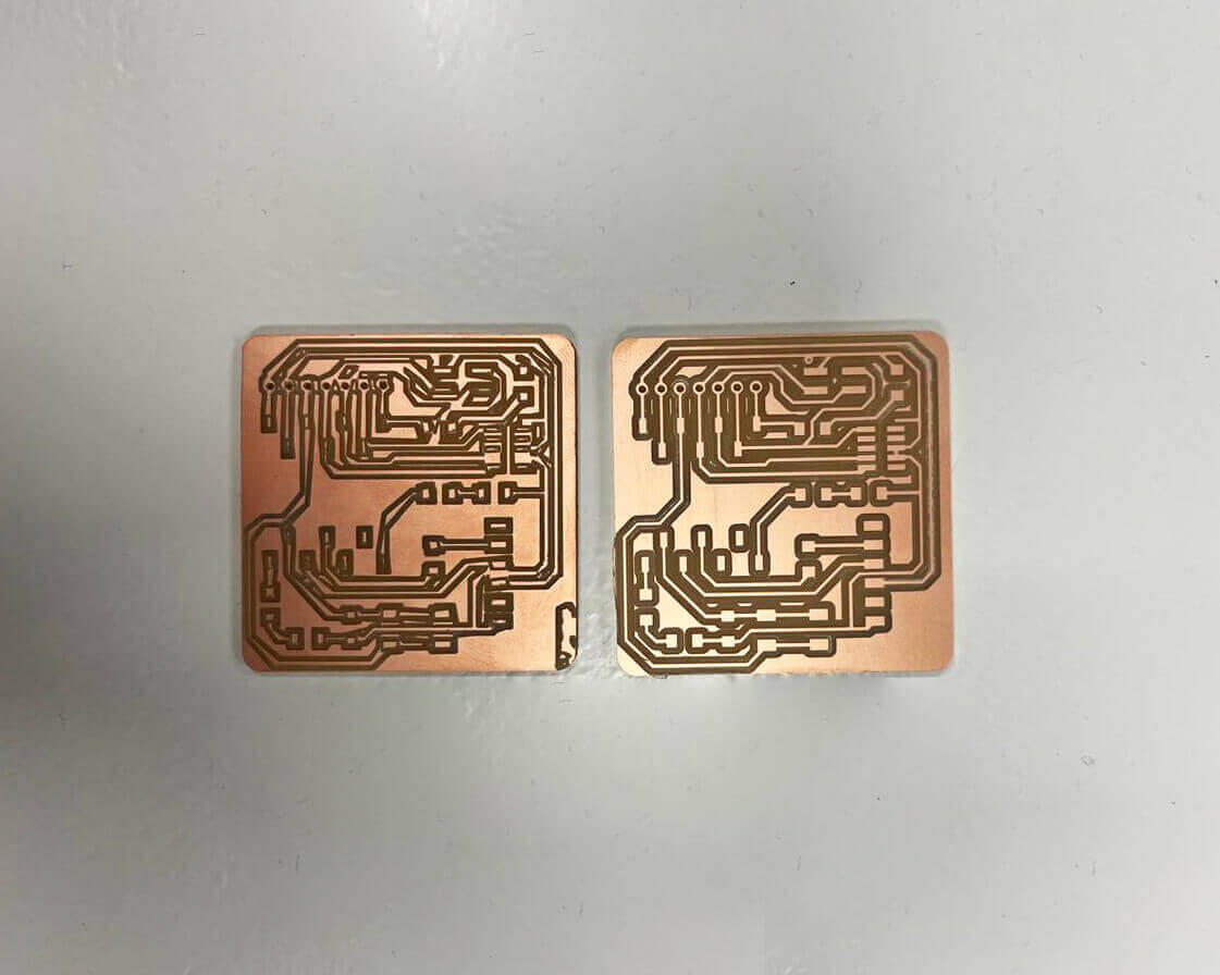
Check PNG resolution before milling
When I made the customized PNG file I did a "SaveAs" on Adobe Illustrator without checking the final image size. Left pcb: the resolution was low so the trace is edgy and not smooth. Right pcb: clean and smooth traces.
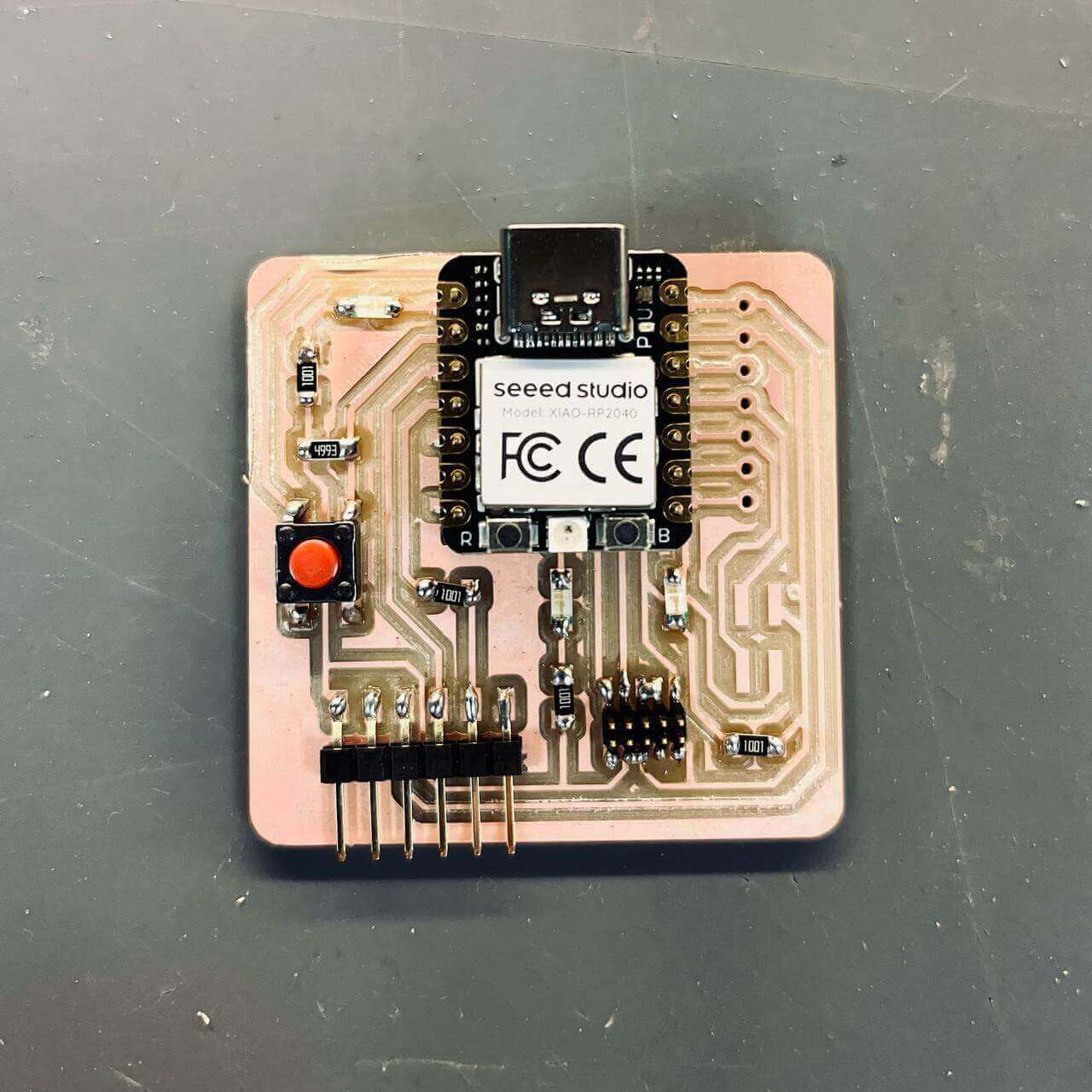
Components + Soldering
1. Look for the components at the Lab proposed from the Quentorres reference (tape them so you don't loose them because they are very small)
2. Have everything ready for soldering
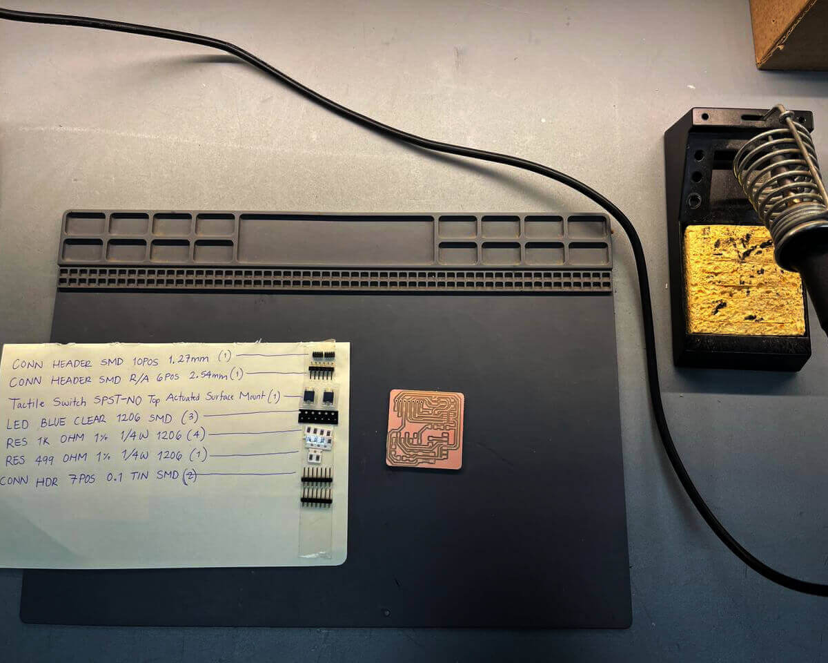
Learning on how to read the components on the board:
- R: Resistors
- J: Header
- LED: LED pins + follow the orientation of the arrow when soldering the piece
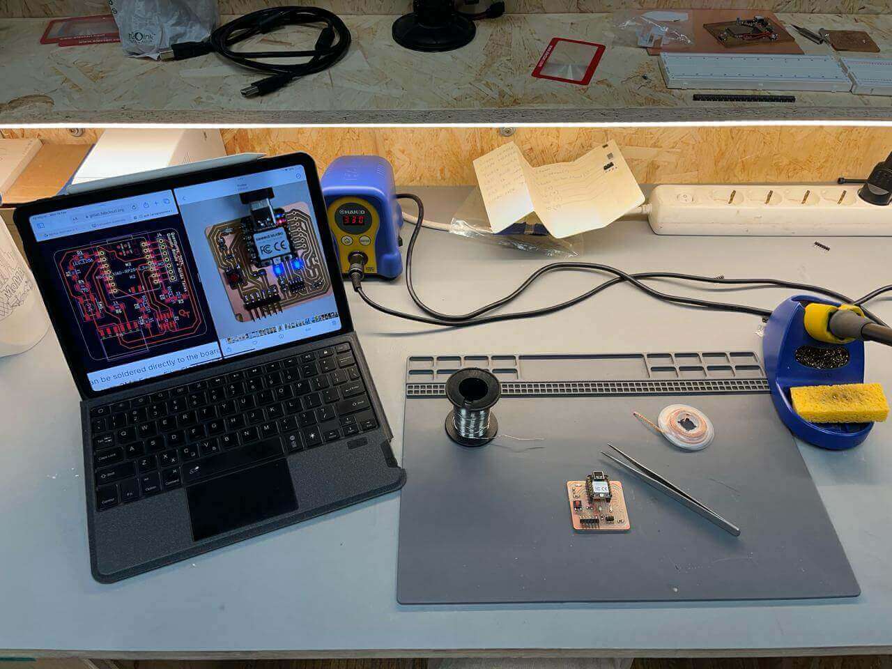
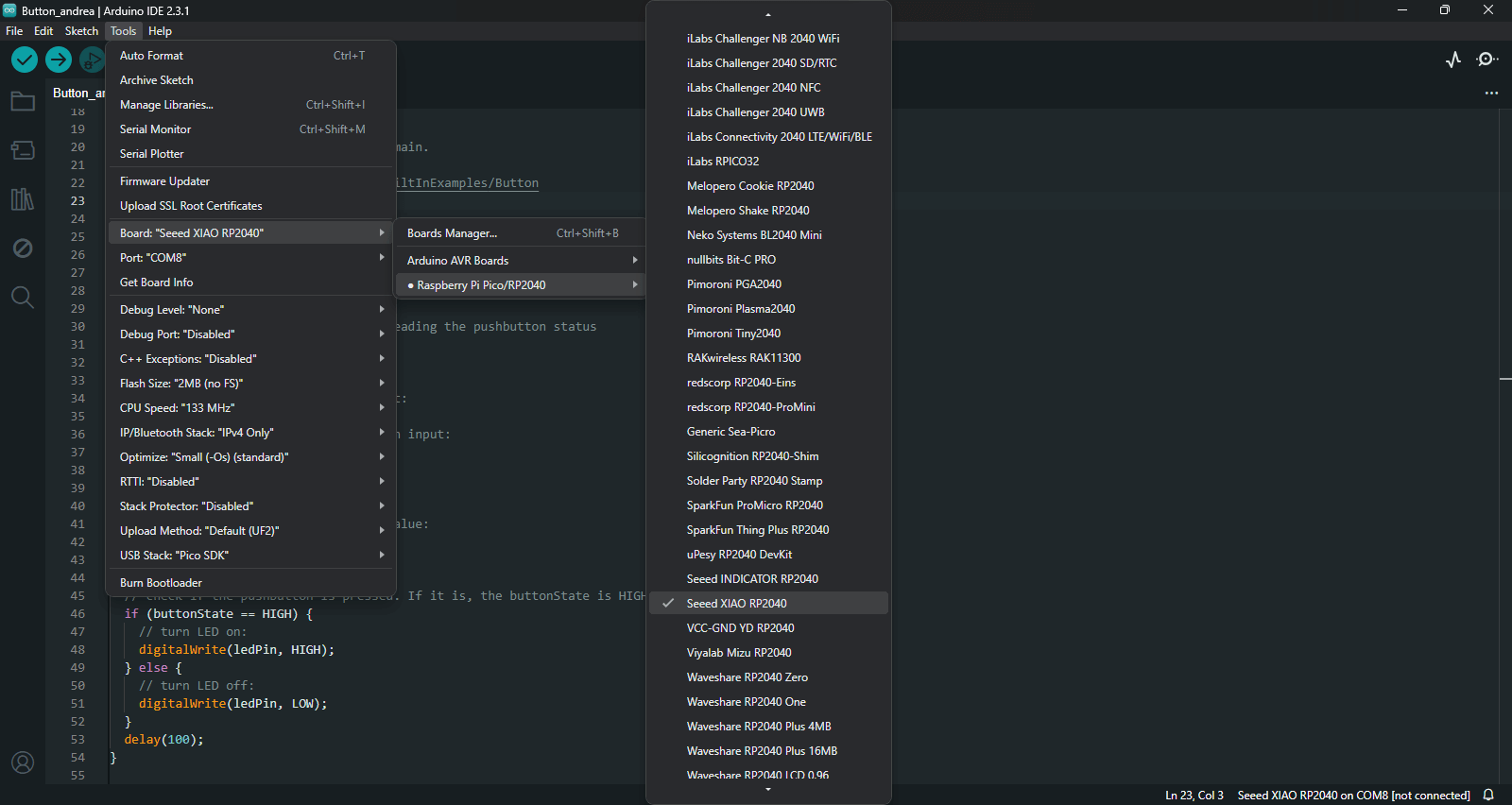
Arduino set ups
Raspberry Pi Pico processor + Seeed XIAO RP2040
1. Download Arduino IDE and follow the instructions on the Quentorres reference
2. Open Arduino / Preferences / copy and paste on the additional boards manager the URL from Pico processor
3. After following the instructions and downloading the processor look for the specific board.
4. Tools / Board / Raspberry Pi Pico / Seeed XIAO RP2040
.png)
Excercises Seeed XIAO RP2040
"Blink"
1. Clik on: File / Examples / 01.Basics / Blink
2. Indicate the location of each LED pin:
- const int ledpin = 26; // the number of the LED pin
- const int ledPin1 = 1; // the number of the LED pin
- const int ledPin2 = 0; // the number of the LED pin
3. Set the LED pins as outputs:
- pinMode(ledpin, OUTPUT);
- pinMode(ledpin1, OUTPUT);
- pinMode(ledpin2, OUTPUT);
4. Arrange the loop between the voltage levels:
- digitalWrite(ledpin, HIGH);
- digitalWrite(ledpin1, HIGH);
- digitalWrite(ledpin2, HIGH);
- delay(1000); indicates a transition for a second
- digitalWrite(ledpin, LOW);
- digitalWrite(ledpin1, LOW);
- digitalWrite(ledpin2, LOW);
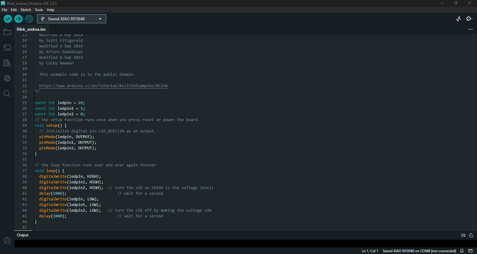
5. Upload to Seeed XIAO
Resources
Josep Martí // Fab Lab Barcelona lead instructor
Adai Suri // Fab Lab Barcelona instructor