Week 03 - Computer Controlled Cutting
Group assignment
On the link below you can find the complete process of this week's group assignment, covering machine usage and setting up parameters such as Power / Speed / Frequency.
Cutting and engraving were mainly explored in plywood 4 mm, as well for calculating kerf values.
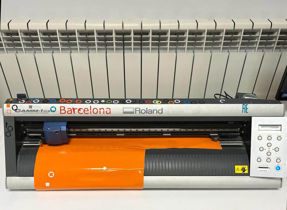
Group assignment pageVinyl cutting with Roland GX-24
Machine prepping + Rhino direct print
- 1.Selecting vinyl color/style and introduce de roll or piece into the backpart of the machine.
- 2.Align the material between the white tapes and the gray tray for a correct print.
- 3.Move rollers according to the material and check on screen that the machine is reading the material (roll or piece)
- 4.Define cutting point and print a default test.
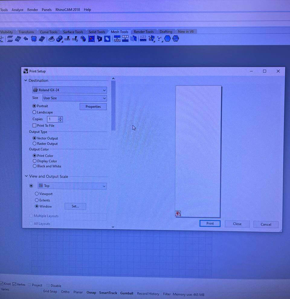
- 5.You can find the process of bitmap tracing with Inkscape on Week 02 assignment and save.
- 6.Open file in Rhino and press print to adjust machine settings.
- 7.Press properties to obtain the size of your material directly from the machine.
- 8.Locate preview of your work on the origin point/corner.
Results
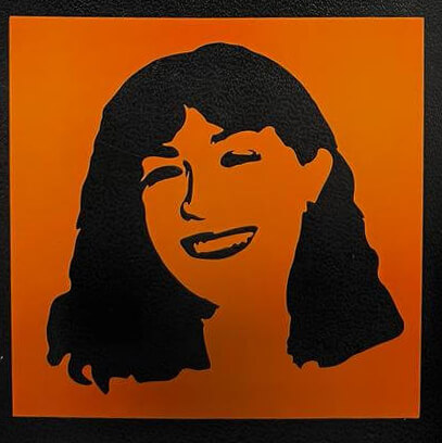
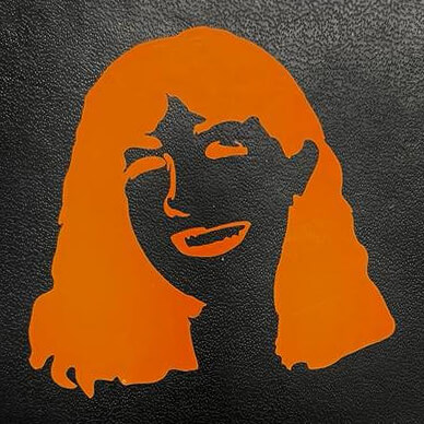
Using transfer paper to remove unwanted pieces and relocate them to the new surface. Negative and Positive selfie trace!
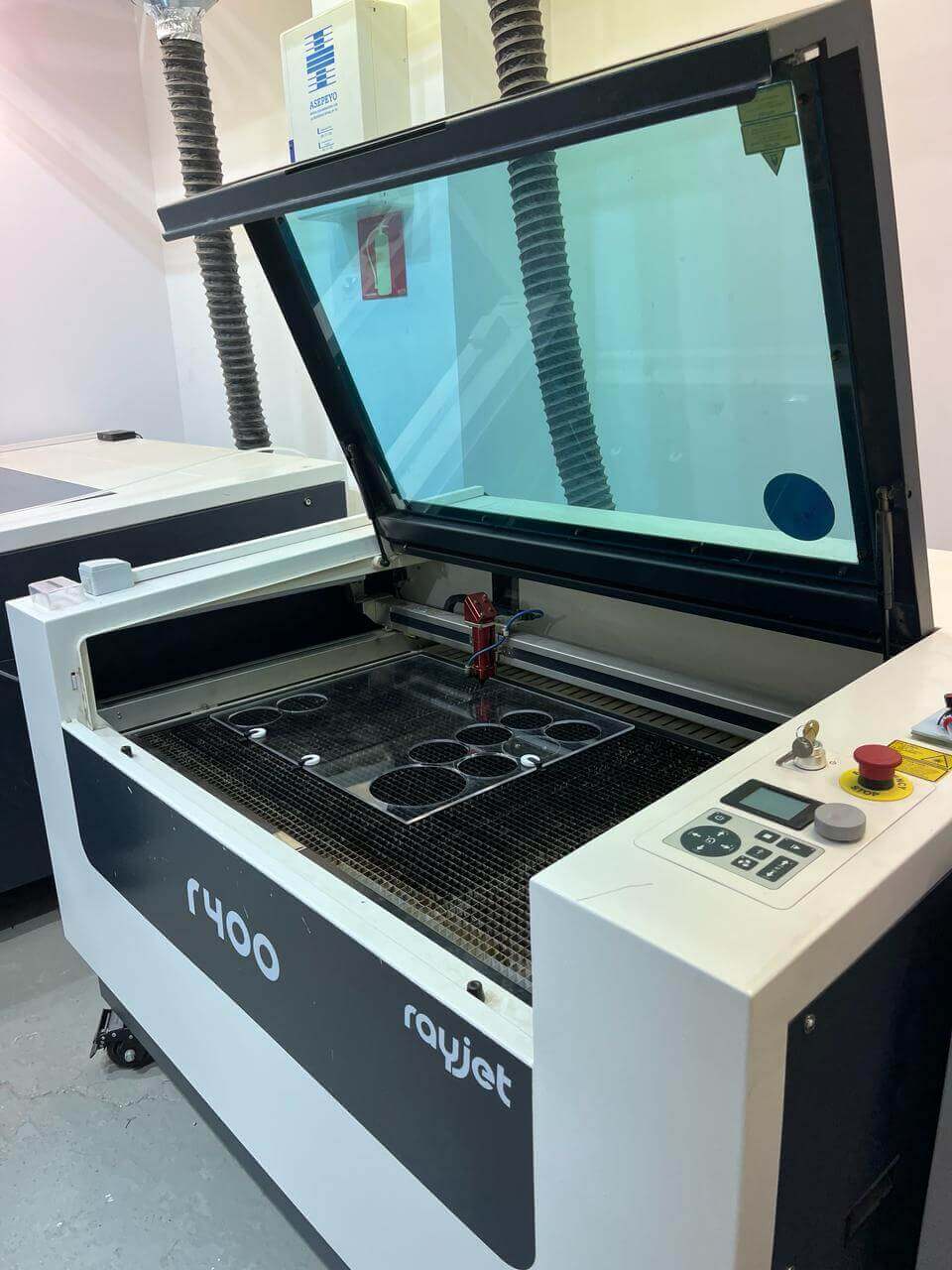
Laser cutting with Rayjet 400
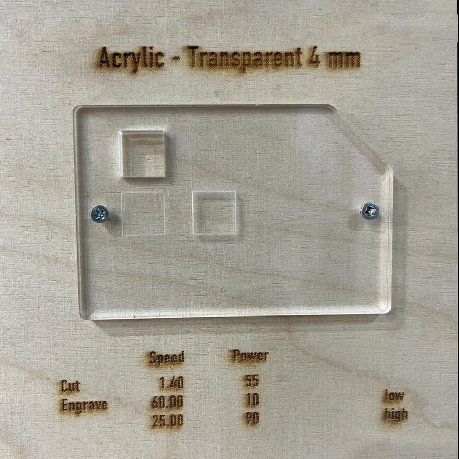
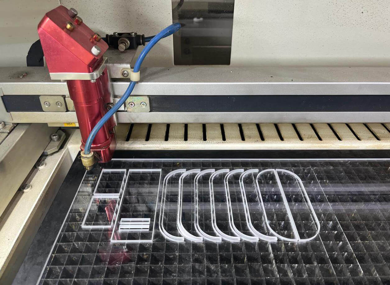
Final project initial mold - Acrylic 4mm
For Week 2(Computer Aided Design), I 3D modeled the first shape for my final project idea. I decided to use acrylic because I want to later on expose the electronics inside of each gadget, plus understand the tolerances and fittings for the machine.
The following steps and parameters were used according to the lab's machine and previous tests:
- 1.Hold material: make sure your material isn't warped, and tape the perimeter to the bed where the laser won't affect it.
- 2.Level cutting bed: with a special tool and your material already set, move the cutting bed up and down so the laser detects the cutting tolerance.
- 3.Rhino workflow: all 2D must be joined into a single polyline + drawing must be near to 0,0,0 + separate your layers according to what you want to do (engrave, cut1 or cut2) + Save file.
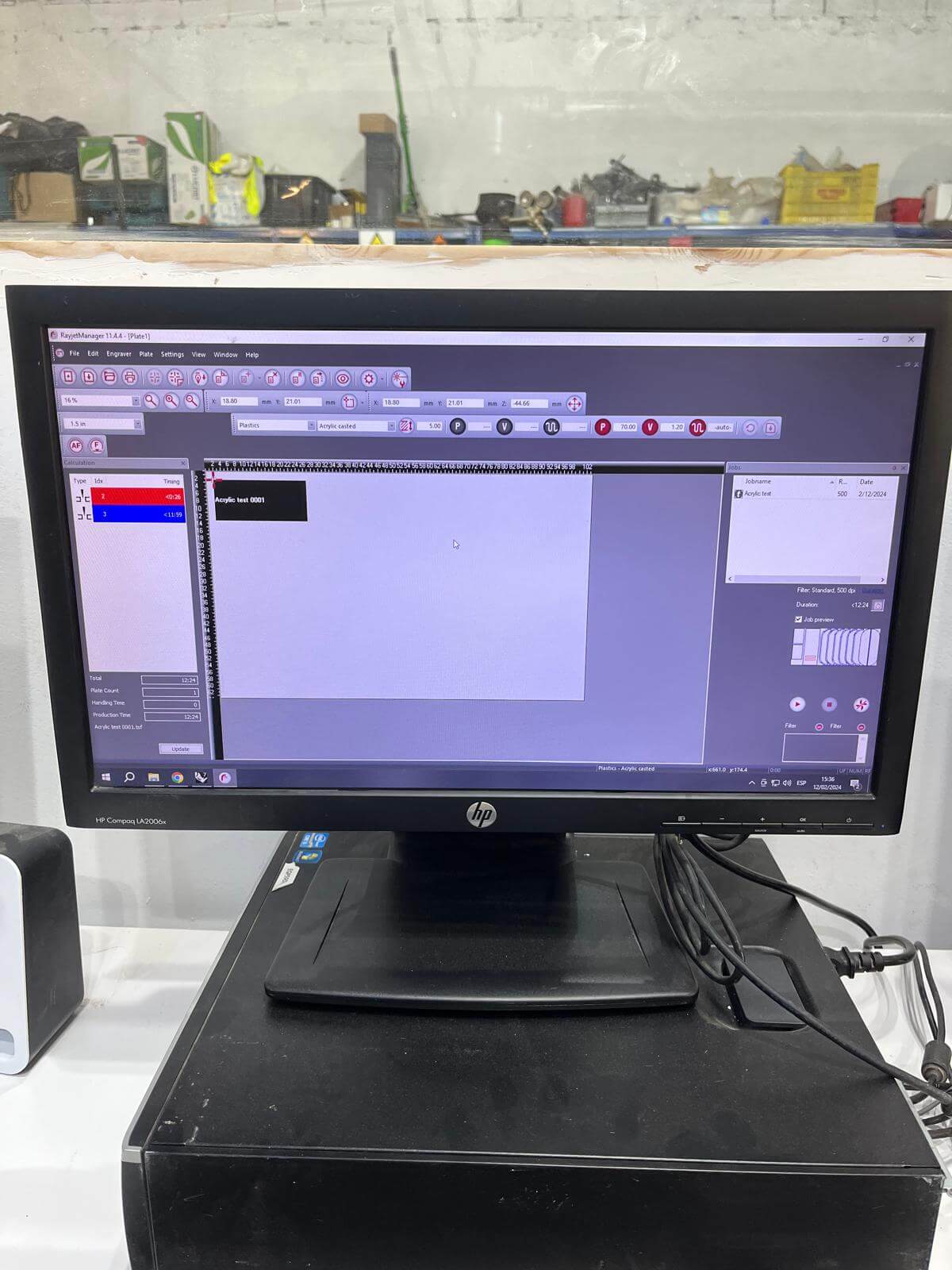
- 4.Rhino to Rayjet: in Rhino select the elements to cut and click on Print, later select Rayjet and it will open automatically into the software.
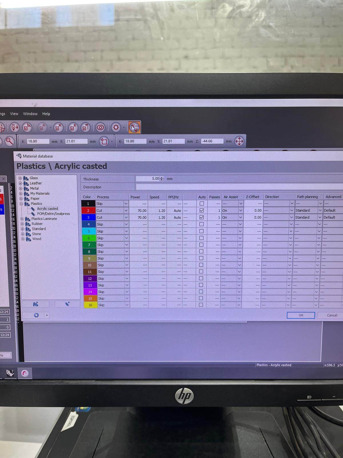
- 5.Rayjet parameters: choose the material that your going to cut + thickness + add the values from already tested piece (view image from acrylic reference).
- Select the layer order according to functions (example: if you want to engrave, that would be the first layer, following the inside cuts and last the outter cuts).
- 6.Select cutting area: locate and indicate the area that your cutting + send file to the machine
- 7.Cut: select file on the machine, make sure you can preview your file on the machine's monitor and Cut.
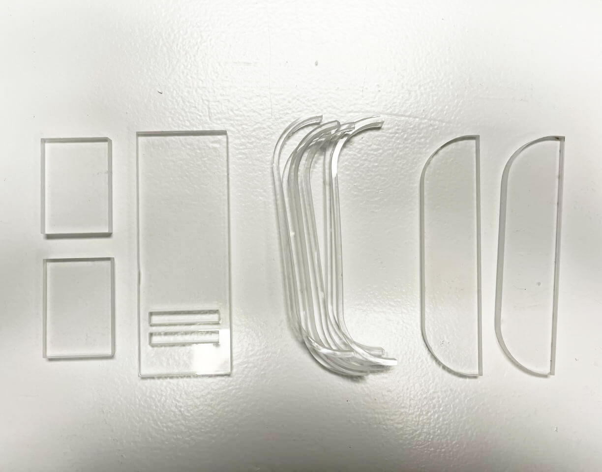
Results & Learnings
In the end, I had to send the cut file for a Third round because the cutting parameters weren't enough to go through the acrylic.
My finals settings for cutting were: 75 power.
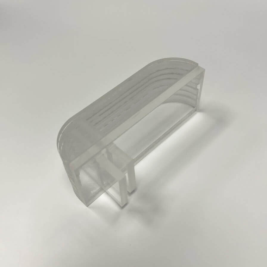
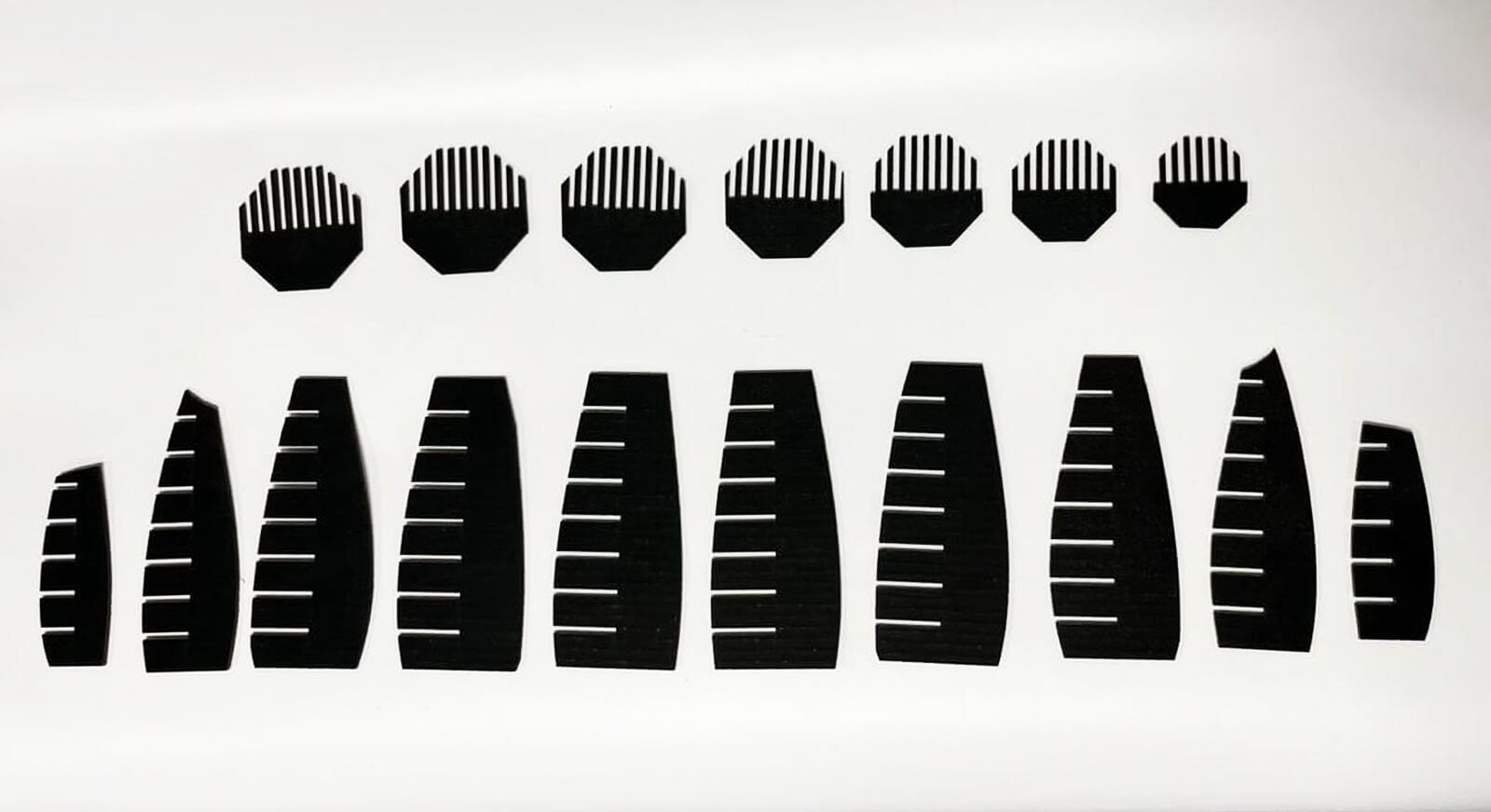
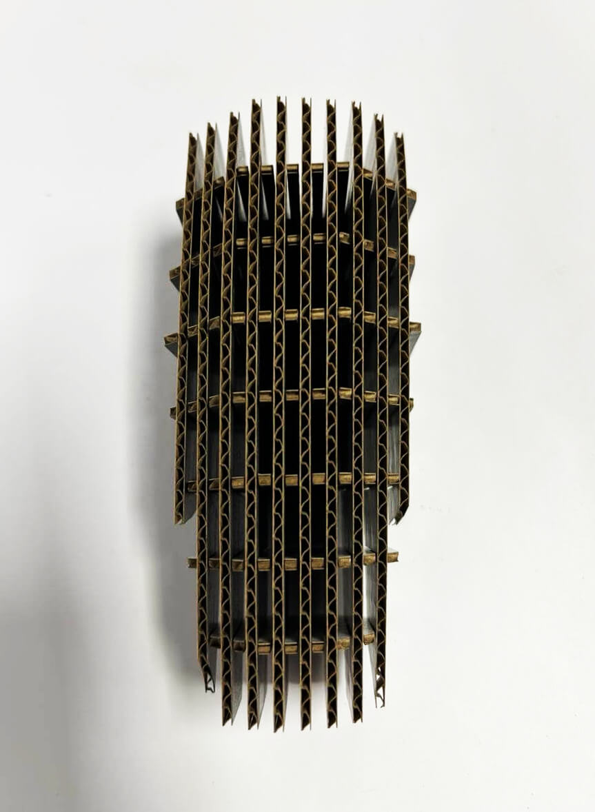
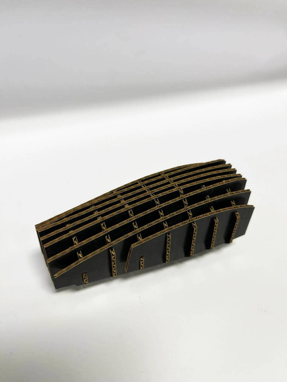
Parametric construction kit
Design concept
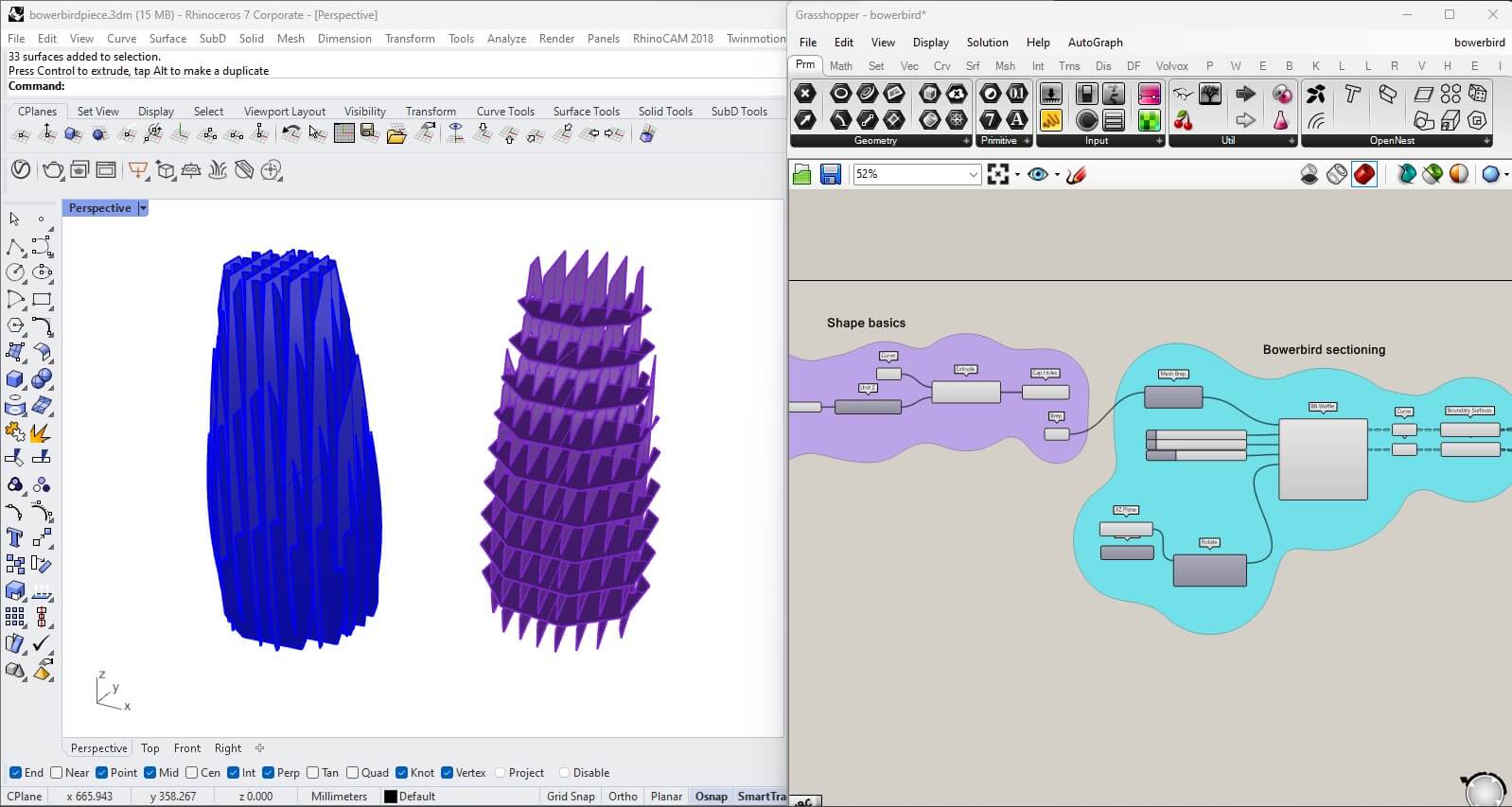
The shape is based on the morphology of the 3D design from Week 2 for the final project gadget. I wanted to generate a GH script based on a basic shape that I could later on transform in a variety of layers.
The video below shows the possibilities of working with different shapes and tweak the ammount of pieces.
Grasshopper settings
Steps for understanding and managing the script:
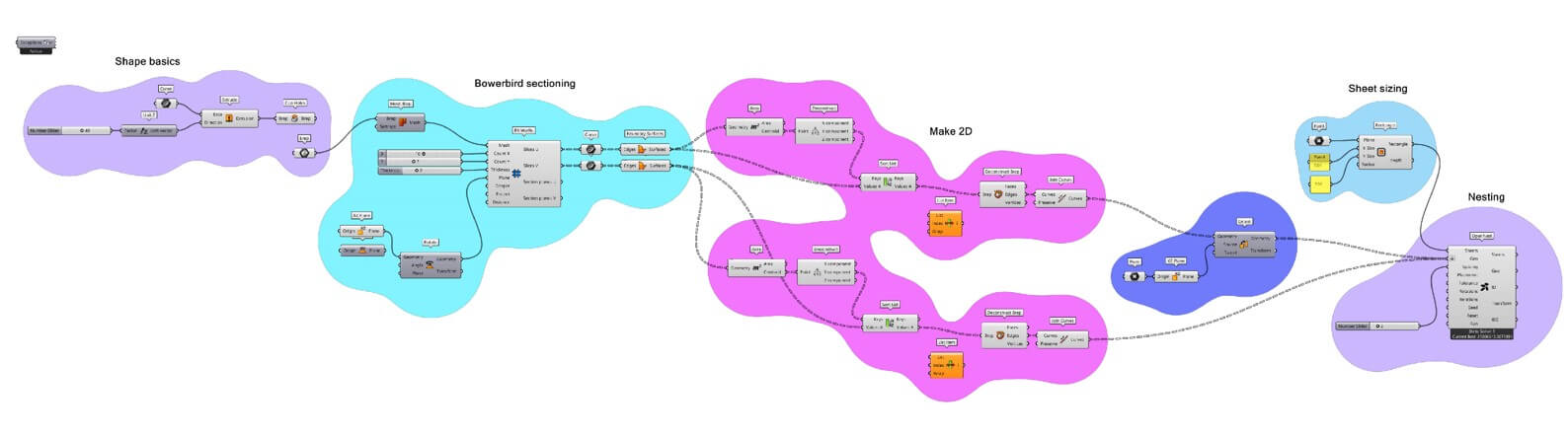
- 1.Shape basics [purple]
- Create desired shape from scratch or add brep.
- 2.Bowerbird parameters [cyan]
- Install pluggin "Bowerbird" which focuses on waffling. Tweak X,Y and material thickness parameters to obtain surfaces.
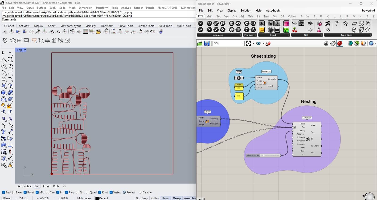
- 3.Surface to Polylines [magenta]
- Obtain edges from final surfaces in order to have linework for future laser cutting.
- 4.Orientation converter [violet]
- In order to orient the pieces from YZ position and being able to spread the pieces for layering.
- 5.Sheet sizing [blue]
- Simple slider to add the size of the sheet that will be used for cutting.
- 6.Nesting [light purple]
- Using Open Nest pluggin and tweaking parameters for adjusting the distance and spacing between pieces layering.
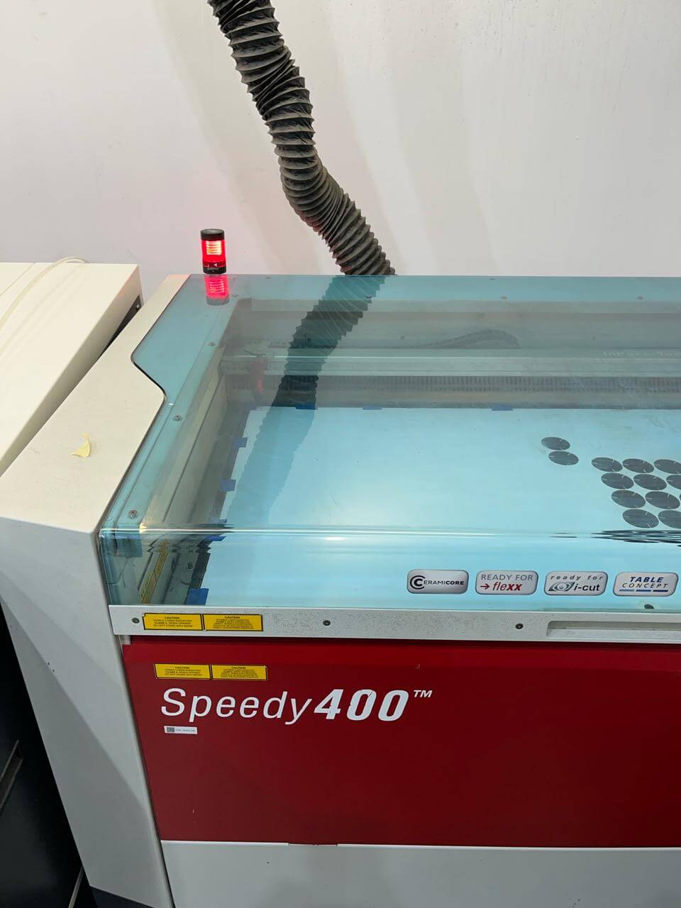
Laser cutting with Trotac Speedy 400
Follow the steps from 1 to 4 from the acrylic model, take in consideration that the next parameters were used according to the lab's machine and previous tests:
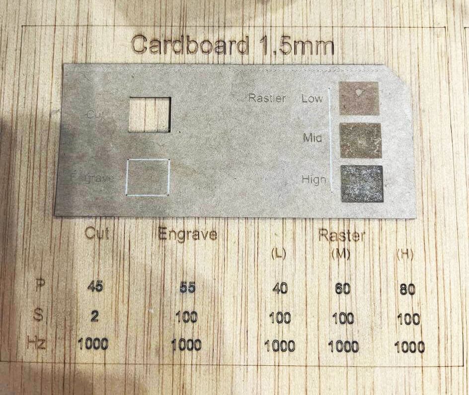
- 5.Trotac Speedy parameters: choose the material that your going to cut + thickness + add the values from already tested piece (view image from carton reference).
- Select the layer order according to functions (example: if you want to engrave, that would be the first layer, following the inside cuts and last the outter cuts).
- 6.Select cutting area: locate and indicate the area that your cutting + send file to the machine
- 7.Cut: select file on the machine, make sure you can preview your file on the machine's monitor and Cut.
Results & Learnings
Make sure to measure properly the thickness of your material because that will define the tolerance you need for the pressfit kit.
In my case, I did not have the correct thickness so the pieces were very loose and had to cut for a second time. Also same happened with the cutting parameters, didn't go through the material.
My final settings for cutting were: 55 power and tolerance with a 3mm cardboard of: 3.1mm
Resources
Files
Download the Rhino + GH ZIP package here.