Week 10 - Mechanical Design & Machine Design
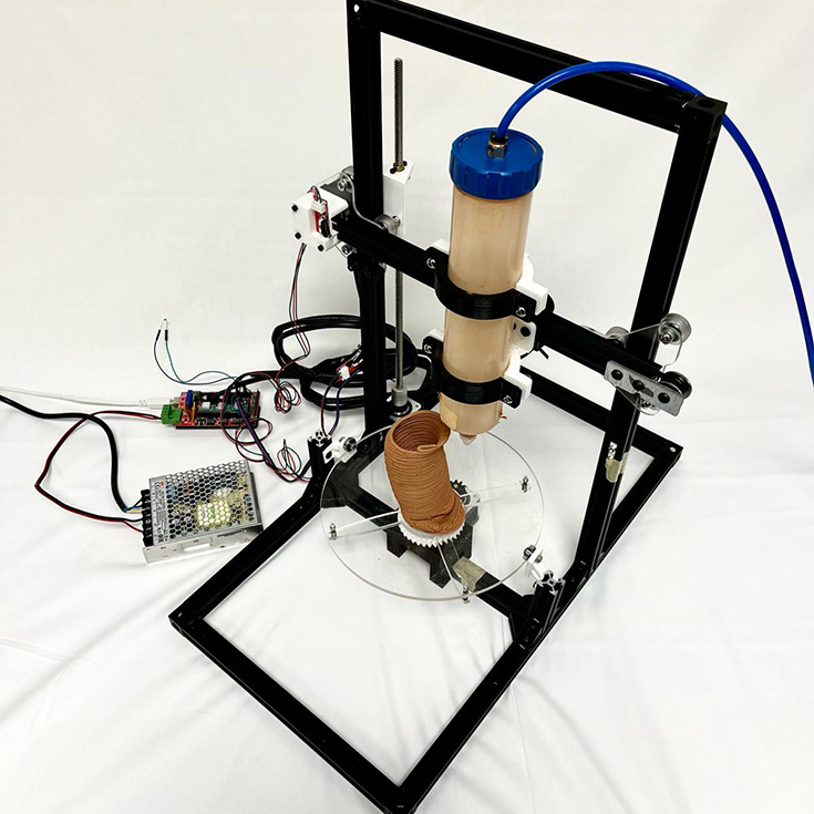
ROTA: polar paste 3D printer
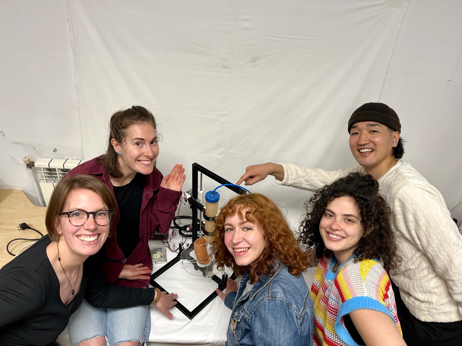
For this week's assignment, we decided to design and build a paste printer. You can check the process and final outcome at our Group page.
3D modeling: re-designing & adapting parts
My main contribution for ROTA, and the first tasks to begin developing our machine was to understand and locate the parts we needed to re-design for our existing elements (frames and screws). For that, we used a Creality Ender 3 Pro model that I previously downloaded as a base for my final project.
I assigned which parts could be directly converted for 3D print directly. We chose to match the Enders aesthetics and use it as a structural reference since we had access to the digital and physical machine itself. You can download it from here: Creality Ender-3 Pro
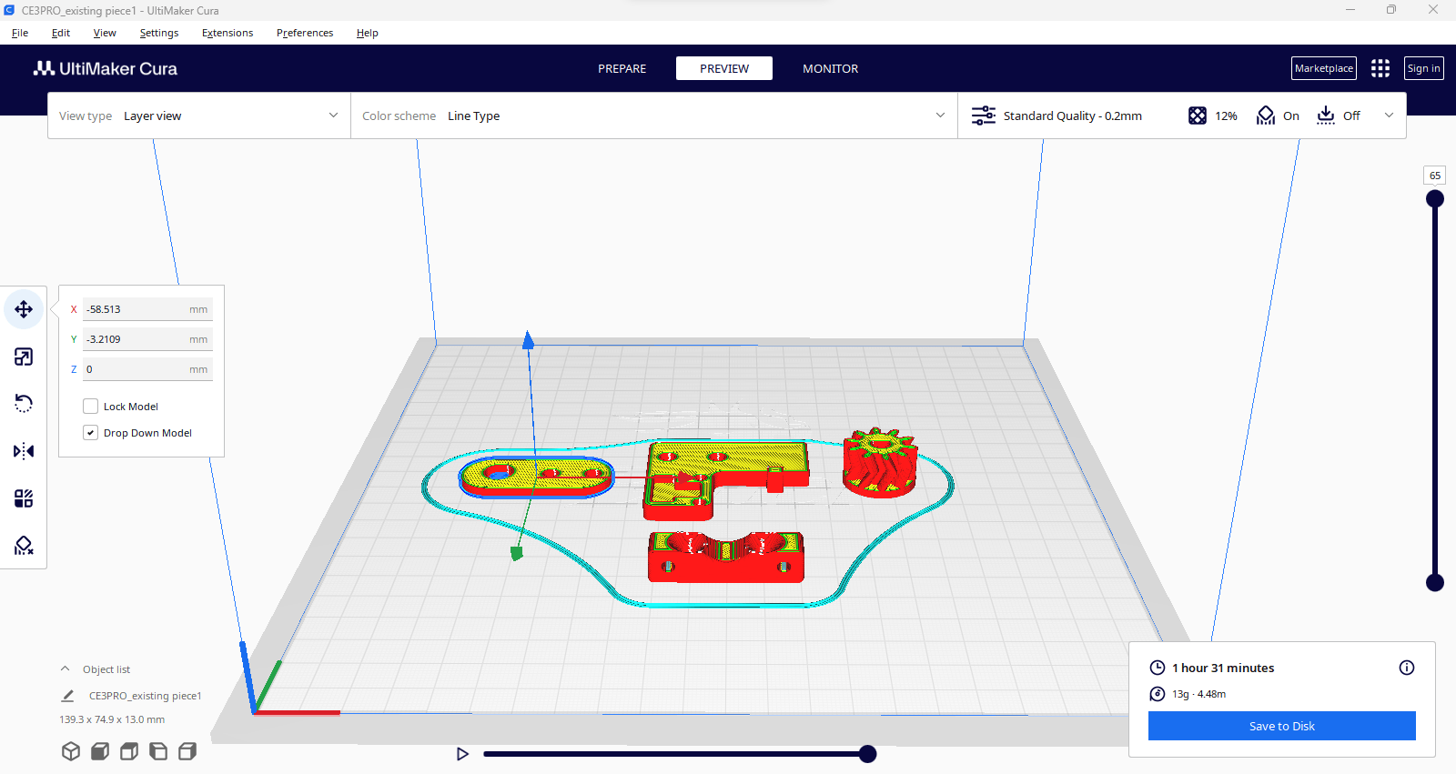
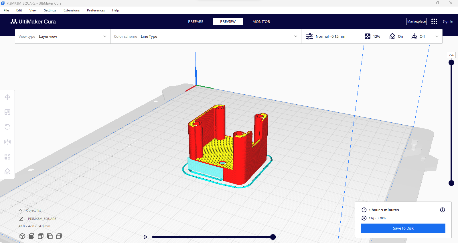
Cura settings: PRUSA + Creality Ender Pro
At the lab we have 2 types of 3D printers, so depending which one was free at the moment are the parameters for each piece.
I mainly used the medium default quality for the final pieces since they aren't necessarily structural. Settings to consider:
- 6mm thickness PLA for both printers.
- Infill: 10 to 12% and line type (for faster print).
- Supports: Everywhere and lowest quality so it's easy to break.
Learnings
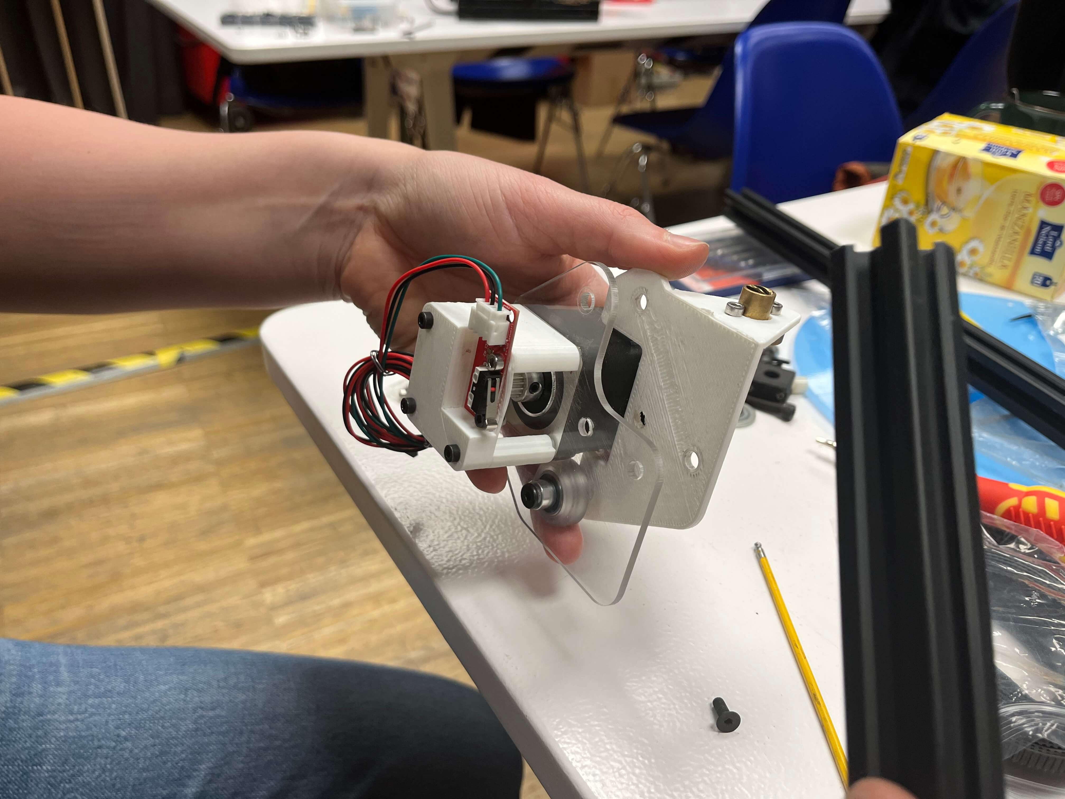
- 1. Make sure to collect as soon as possible all the screws, washers and nuts for each piece. So you can adapt the hole sizes tolerance and not until the very end and have to re-print.
- 2. All metal pieces that need to be printed, you should initially modify the hole tolerances to .5 mm extra. The PLA resolution isn't as precise, it distorts very slightly but enough for not being able to fit screws.
- 3. Same issue as number 1 but with electronic components. We had different endstops which made us to re-design the part thinking it would be a direct print.
You can preview and download the complete selection of parts adapted for ROTA here:
ROTA - polar paste printer by andrearubio18 on Sketchfab
Animations for video
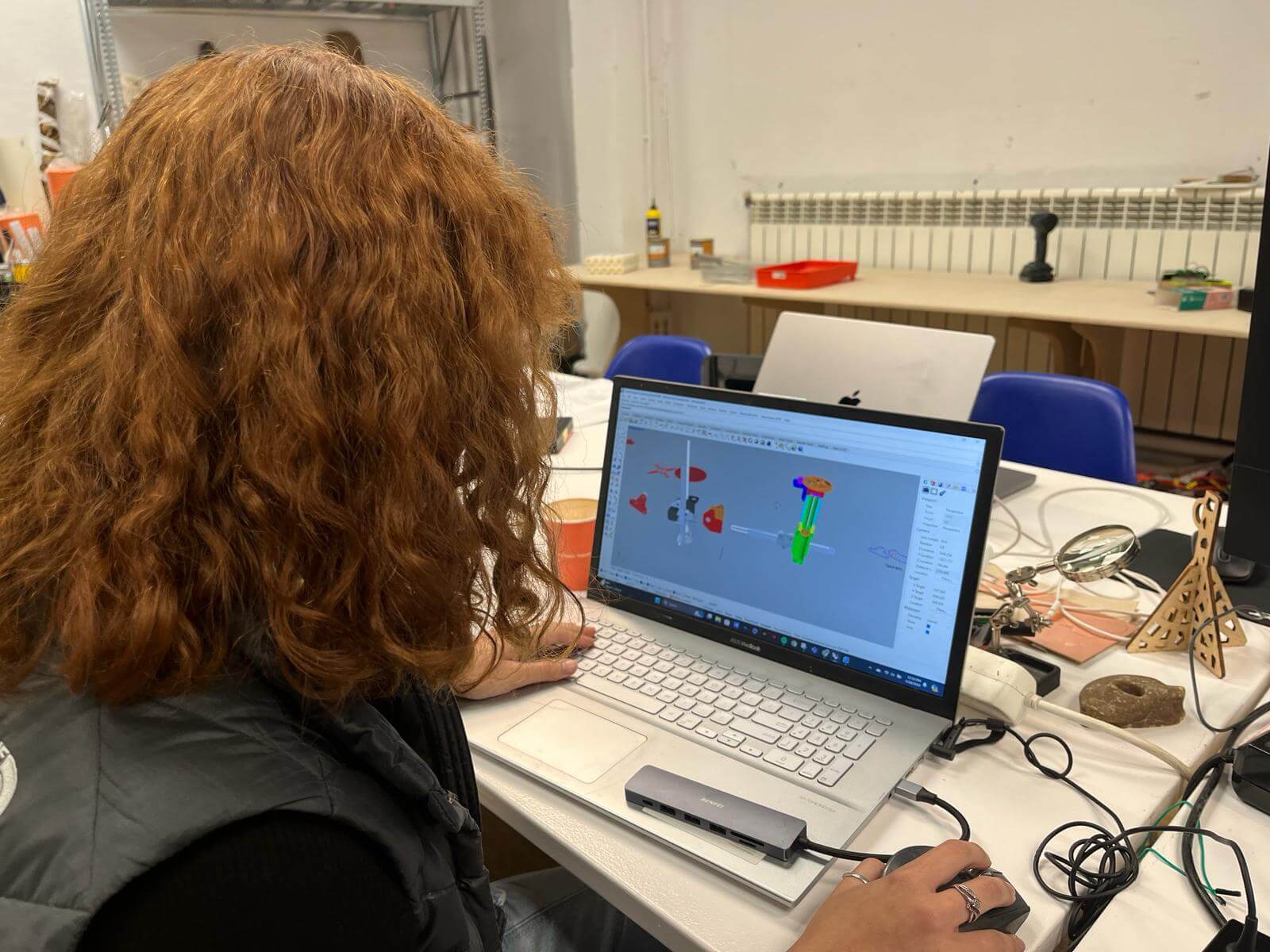
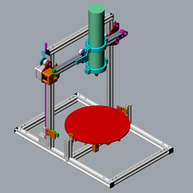
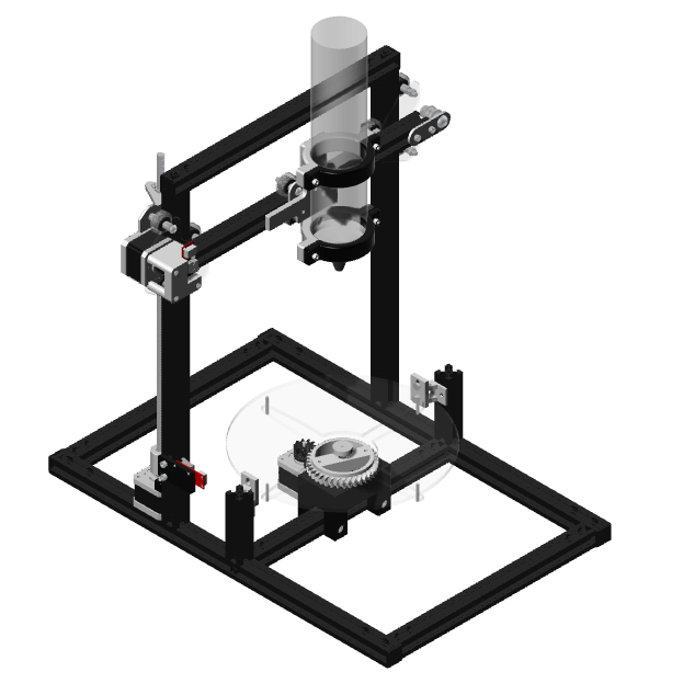
After compiling the complete 3D model with the adapted parts and running some movement test, we decided that it would be nice to simulate all the parts of the machine in action with a better visualization.
To achieve this, I used Rhino 7 and an online video maker. To follow the process read the next steps:
- 1. Activate render view and change all the textures of the parts and components to achieve a "realistic" view.
- 2. Save the angle view you want to animate.
- 3. Group the elements that are being moved (in my case, the cartridge holder and structure + rotating bed).
- 4. Set up a dimension for you to remember how much you will move forward, side, backward, etc.
- 5. Save 0,0,0 view with the original position of the elements you want to move by typing ViewCaptureToFile.
- 6. A window will appear, select a good quality size for your images and pick either PNG or JPEG format.
- 7. Repeat steps 5 and 6 with each frame.
- 8. Download all frames to any video or GIF maker online.
Note:Depending on the use, make sure your images aren't so high quality because the majority of the online makers have a weight limit.
Issues: Marlin 360
First error: “MINTEMP triggered error”
We looked up the error in a RepRap blog where one of the solutions suggested was to add a 100K resistor to the board over the Thermistor pins and set it to Type 1 and it worked: we tested all the axis motors to move.
Note: We continued moving the motors through serial monitor and modifying the speed. First try was: G0 X100 F500
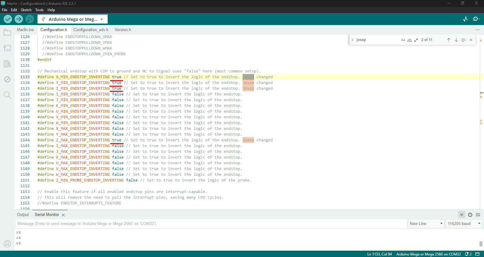
Second error: “END-STOP hit”
Solution: in firmware, invert the state of end-stop to false. Same for the software end-stops change to false.
Note: by default it detects the maximum value to stop, once it’s FALSE you can stop it with the physical end-stops. But remember to go back and re-activate it once you define the length or height.
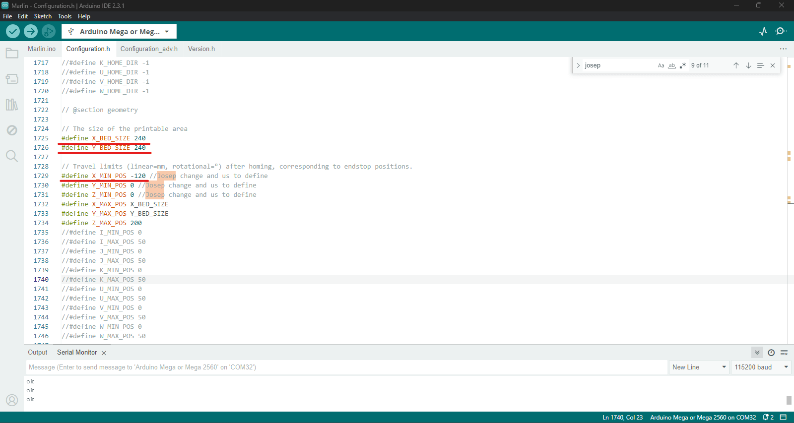
Substitute values at: X_MAX_POS
Tests: Assembled hardware + Marlin 360
Note: X axis motor very pressured, the band wasnt moving properly so hardware also needed adjustments.
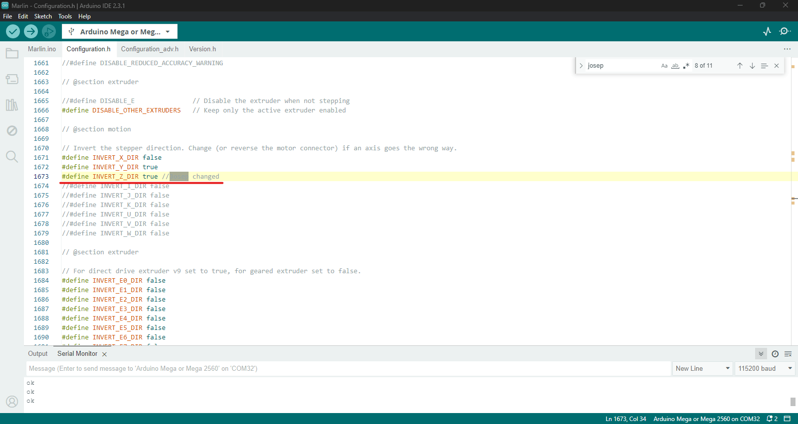
Solution for Z: by using negative values the motor would go up, so on the software we changed the following: INVERT_Z_DIR_ to true. And the end-stop was activated as well.
Modifications
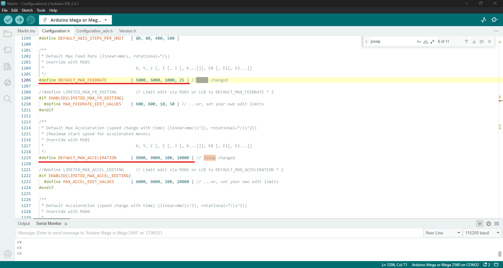
- 1. Change in code the acceleration using: M204 from 3000 to 9000 (maximum value).
- 2.Continue playing values from Step per unit and Feedrate.
- 3. Setting up a base for all motors to the following values: 10,000 Acceleration // 1000 Feedrate
- 4. Hardware: all motors were fixed to 0.6 voltage
- 5. Arranged travel limits after homing: Z_MAX_POS 200000
Set up: Marlin
After trying to understand the Marlin 360 code and couldn't make it function properly, we decided to jump to the original Marlin by changing the same values mentioned previously.
- 1.Inverting endstops: shouldn't be triggered and change them to TRUE (X, Y, Z)
- 2.Endstop settings: USE_XMIN_PLUG // USE ZMIN_PLUG
- 3.Final coordinates: 144 for Y (1 rotation 360), 240 for X, 200 for Z
Calibration to this point:
      DEFAULT_AXIS_STEPS_PER_UNIT { 80,18,375,327 } // coordinates
      DEFAULT_MAX_FEEDRATE { 5000 } // related to homing speed calculations
      DEFAULT_MAX_ACCELERATION { 9000, 9000, 100, 10000 } // X Y Z max start speed for moving
      DEFAULT_ACCELERATION { 3000 } // X Y Z for printing moves
      DEFAULT_RETRACT_ACCELERATION { 3000 } // X Y Z for retracts
Resources
RepRap forums.
Instructables for polar Gcode.
Josep Martí // Fab Lab Barcelona lead instructor
Adai Suri // Fab Lab Barcelona instructor