PCB - Electronic Design & Production
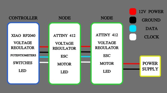
System Diagram
Here is the layout of the electronics. Power supply giving 12v to the boards. Node PCBs outputting to ESCs and motors and the controller board receiving the inputs from the potentiometers and switches.
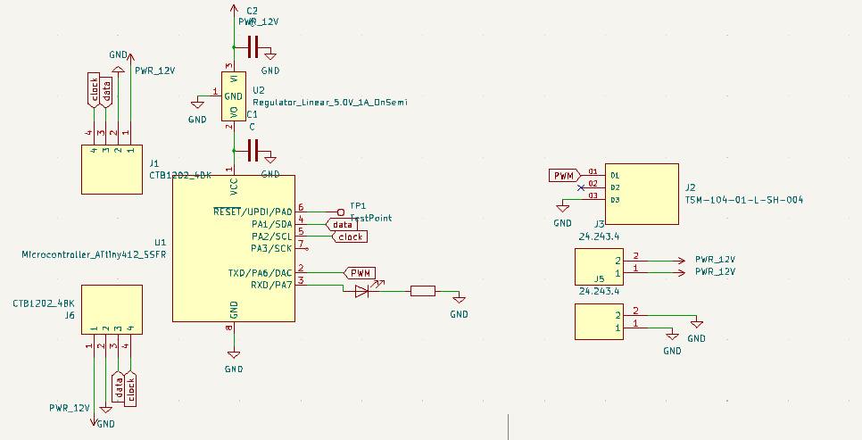
KiCAD
Node Board
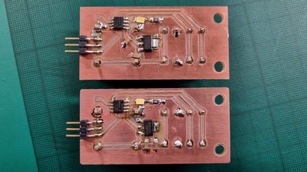
I started with the Node board. It has a mixture of through hole and smd components.
There are plugs for the serial bus lines to run in and out of the board. There were also two banana plug sockets for the power and ground to the esc. As well as a 3 pin connector for the PWM signal to the esc.
We have a voltage regulator to convert the 12v into a 5v power line which is suitable for the ATTiny 412 microcontroller. I initially forgot to add capacitors. Initially we retro-fit them but due to some complications I had to remake the boards anyway so fixed this design flaw.
We also have a LED and its resistor mainly for testing the code.
It took some interations, but I reduced the size of this PCB as much as possible. I discovered that it would be fine to overlap the smd components over the through-hole connectors, fitting them in between the pins.
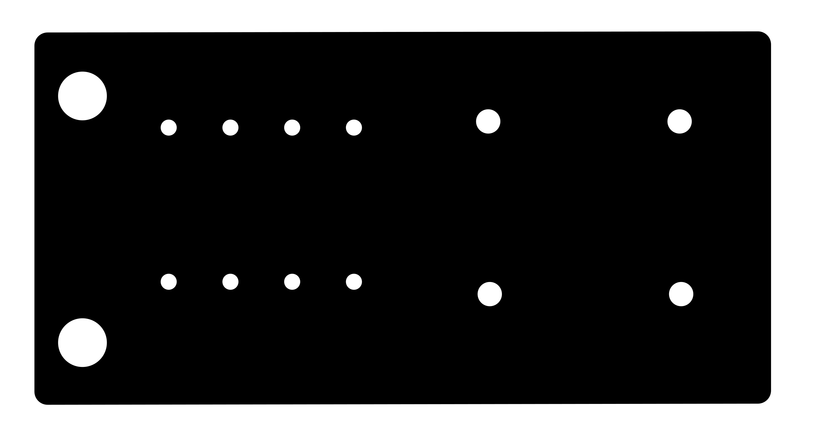
I used 0.8mm track width. I also added some 4mm holes for the PCB to be bolted down.
The components are orientated so that all the wires going to the esc come off in one direction and the bus lines are running through the board at a 90 degree angle.
In hindsight I would have added more dedicated 'testpoint' pads for the UDPI programming as it was fiddly to get a good connection.
Another change I would make would be to use a through-hole LED as it ended up being upside-down so not very visible from the outside.
I also should have protected the microcontroller using a diode from the chance 12v is fed to it.
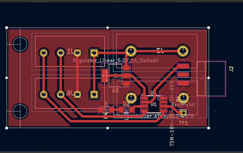
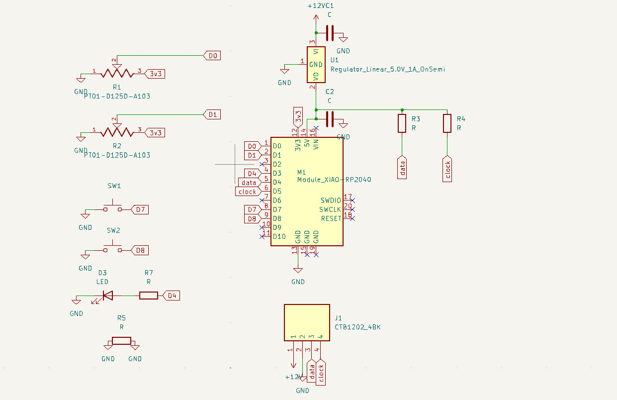
Controller Board
The controller has a XIAO RP2040 microcontroller.
There are four inputs to the board. Two potentiometers, that need to be on analogue pins, and two switches.
The serial bus connector is on this board as well, but this is the end/start of the line so only one is needed.
We have a voltage regulator for the 12v power line and its capacitors.
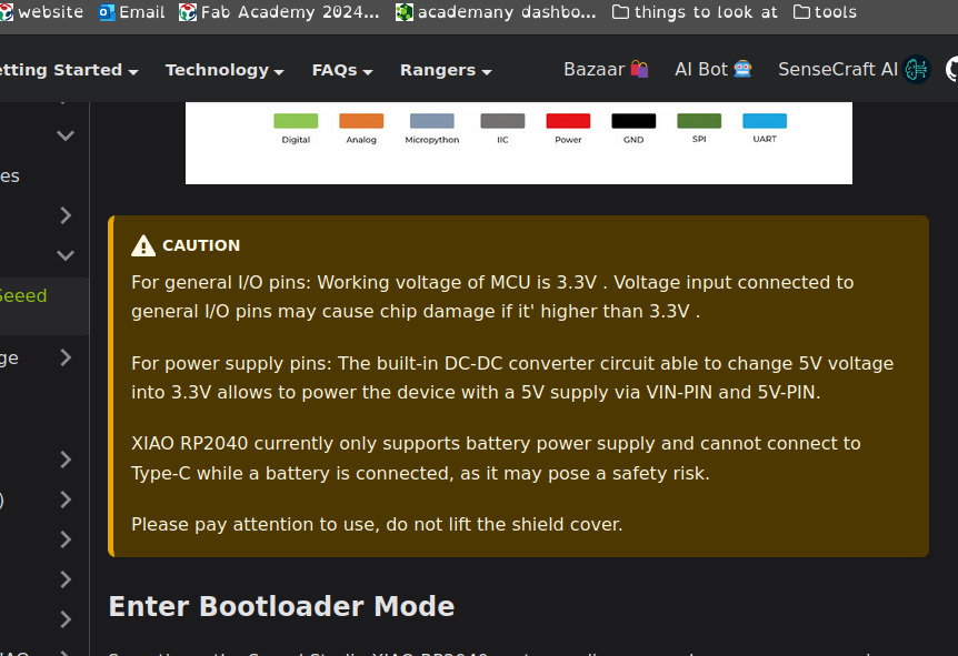
Initially I had the 5vs going into the Vin pin however it isn't designed for this, it is meant for battery inputs. For one it is very difficult to solder smd to a PCB. There is also a warning on the site to not have the XIAO plugged into a battery and a USB at the same time. I did not realise this until I noticed the regulator heating up a lot when I started to code. I fixed this by connecting the 5v to the 5v pin. Initially I thought this was just 5v out, but it can go both ways.
For I2C we need pullup resistors on the data and clock lines, so we have put them on this board.
There is also a led for indication purposes.
I had to add a jumper resistor to connect two ground areas together.
I wanted the controller to be a nice shape, so I decided on a semi-circle. I rotated the potentiometers and switches, so they sat at a nice angle that roughly followed the curve of the circle.
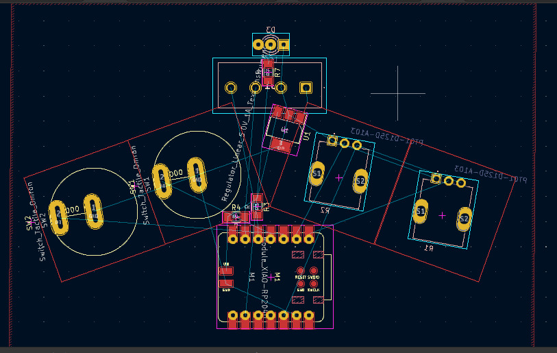
The connector going at the top and the led centrally.
Routing the tracks to the inputs was difficult and I went through a few versions with the rp2040 being rotated and different pins being used. This was the best orientation I found in terms of space and reducing any jumper resistors to one.
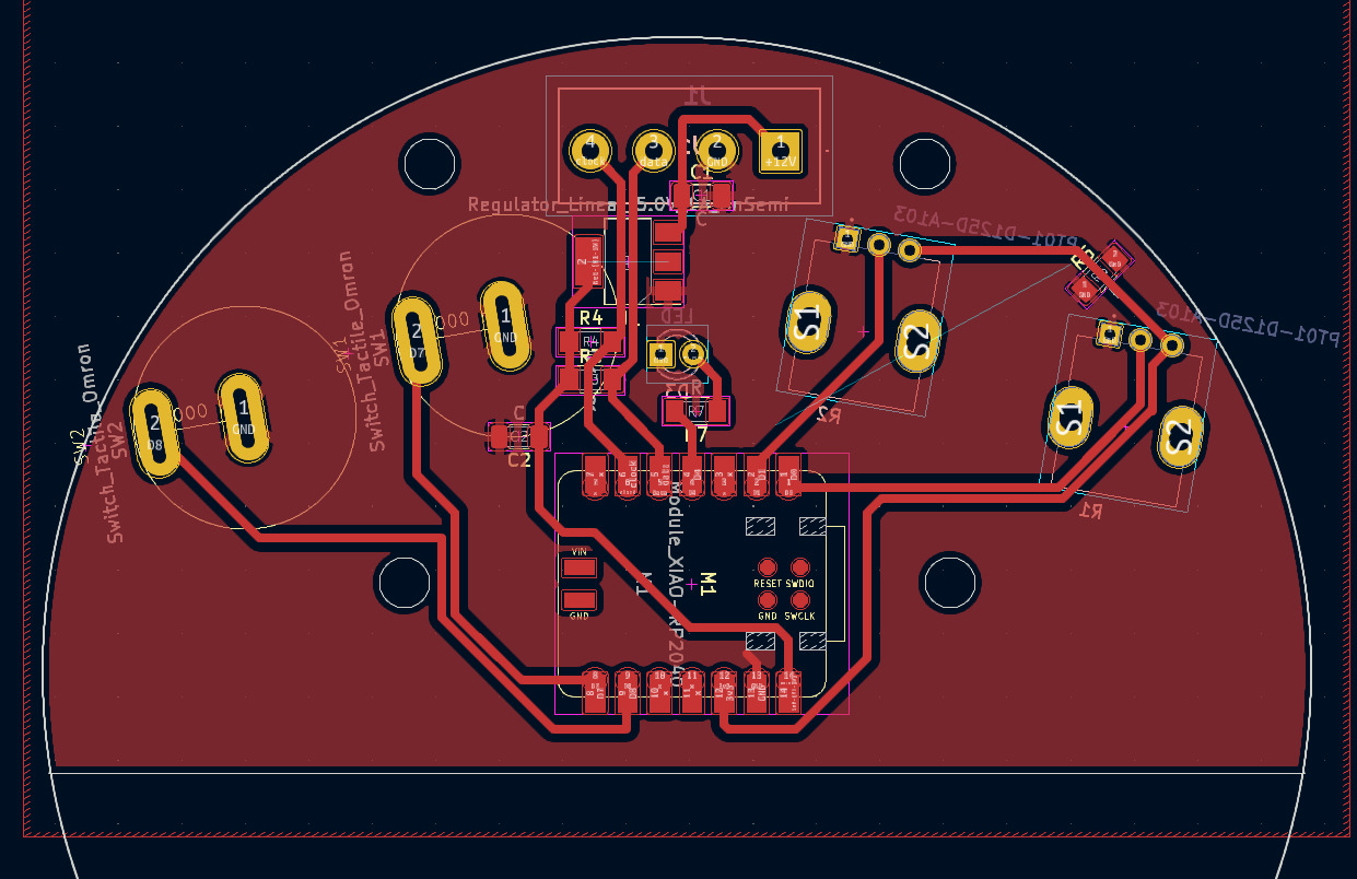
I also added 4 holes to fasted down the PCB, measuring their distance so I could match it up in fusion for the milled holes in the base of the controller.
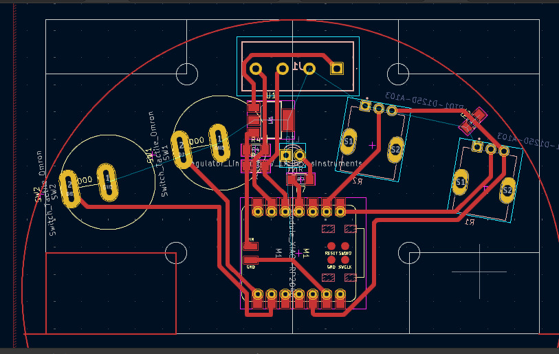
Finished PCB design.
Milling the PCBs
I exported the svgs from KiCAD and opened them in inkscape to make some tweaks and fix the colours.
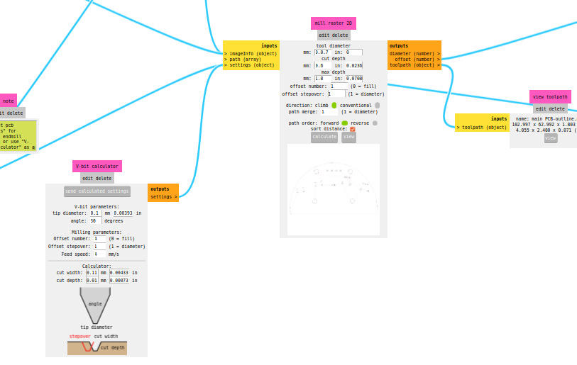
Modsproject
Using modsproject I generated the gcodes for the PCBs.
I used a v-bit for the traces.
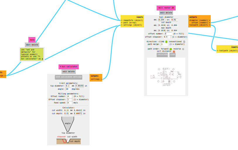
And a 0.7mm bit for the holes and cutout tasks.
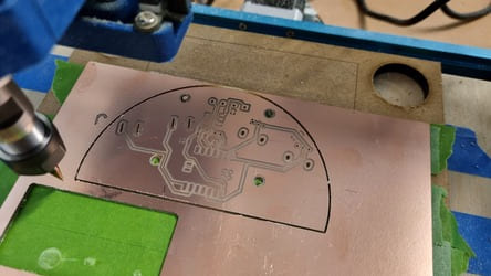
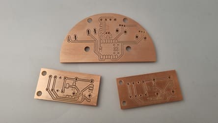
Milling
I used the proVER 3018 to mill the boards. We need one controller and two nodes.
The node boards took about 25mins, the controller 50mins.
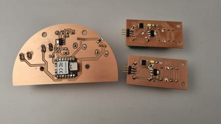
Finished milled boards (I would have to remake some of these due to other issues later on).
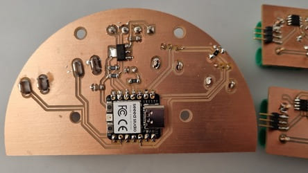
Soldering
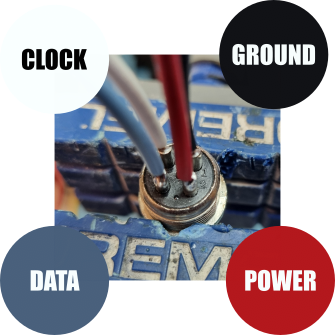
I had to solder all the components onto the board as well as create and run the serial bus wires. I had purposefully chosen different colour wires to they were easy to identify.
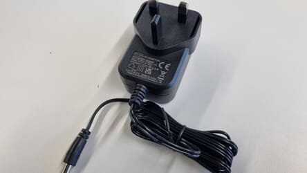
12v 3Amp power supply.
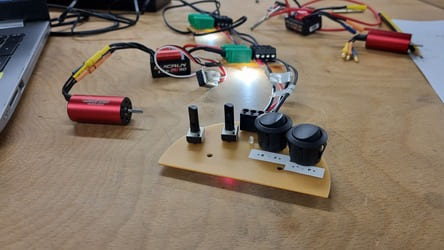
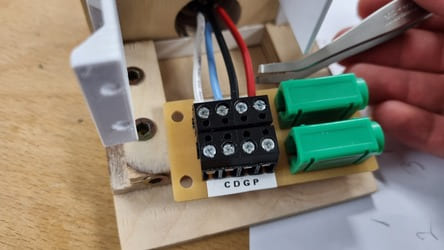
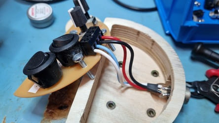
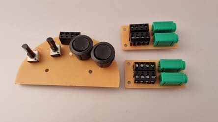
Controller wired.
The ESC has power and ground which plugs into the banana plug sockets on the PCB. They came with two different plugs for some reason, so I had to resolder the second one.
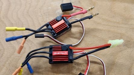
The wires to the motor were too long and the connectors too bulky so one I was happy with the orientation I permanently soldered them to the motor.
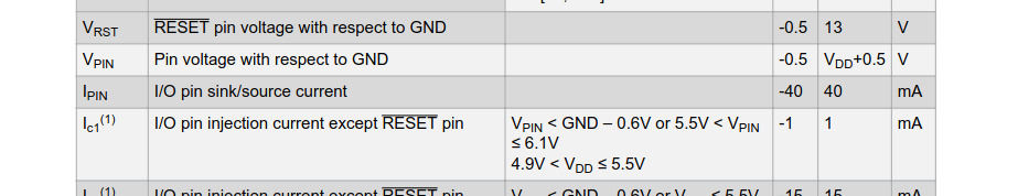
I originally used a resistor for the led which was too low. This meant the max injection current on that pin was too high and after some time it cooked the microcontroller. This forced me to re-mill and solder the boards which was very unfortunate.
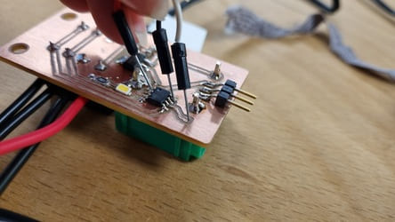
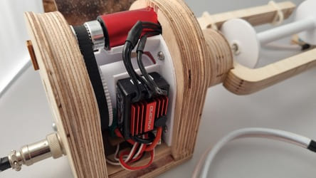
Finished Boards
Boards being coded.