Inner Workings - 3D printing and BLDC motors
The Hub
Inside the hub there are two 3D printed parts with three used on the outside.
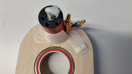
The main one is the drum which provides the channel for the wool to pass through the entire machine. Either the flyer or the collet and nut screw onto this drum on the outside and must spin on this central line.
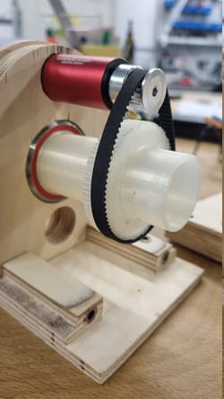
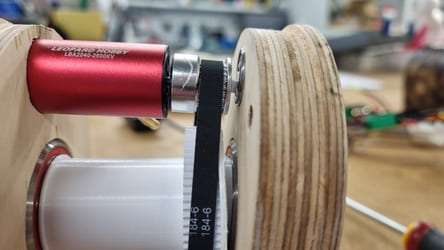
The drum has a pully on the outside which was generated using gt2 gear generator where you can export a dxf which is then imported into fusion. This pully is placed to be in-line to where the motor and pully will sit.


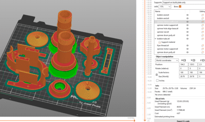
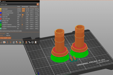
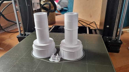
Drum in the slicer and after being printed.
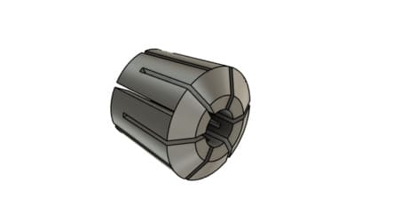
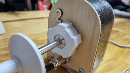
The drum has a tapered angle which the collet slides into which flexes and tightens the collet down onto the knitting needle holding it securely and centrally in the pully.
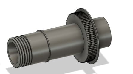
The drum is created using a sketch which is revolved to get this shape.

As this collet is under quite a bit of stress, this is the first print I recommend not printing out of PLA as it is quite brittle. I used ASA as it has good impact resistance and will bend instead of snapping, PET-G or other similar materials should also be sufficient.
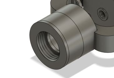
The nut which is used to tighten the collet in place also has a chamfer to increase the surface area the pressure is applied to the collet.

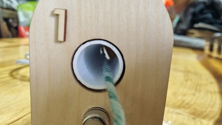
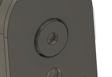
On the other side of the drum where the wool is spun through you use an orifice which reduces the size of the hole that you are spinning through.
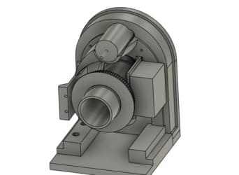
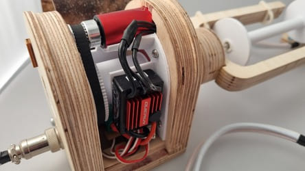
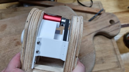
Back inside the machine I quite late on modelled a piece which has three uses to solve some of the issues that came up whilst building the machine whilst keeping everything clear from the drum and bearing.
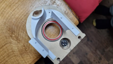
I had planned it originally to just support the motor and guide the cables but then adapted it into a more significant structural piece.
The biggest issue was that the motor did not have enough support which was causing it to be pulled down by the belt tension, so the motor now fits inside a dish keeping it straight.
Secondly, the ESC was not fitting down under the pully because the PCB was too large/the space was too small. There was enough room to mount it vertically between the pully and the shell, so I made a platform for it to be stuck to.
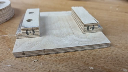
Finally, we had an issue that the walls were not sitting vertical to each other and not sitting in close enough.
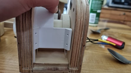
There are likely a few reasons for this, such as uneven sanding after the milling, the threaded inserts not in at a perfect position or angle, the bearings not inserted fully or the wood warping. Either way we ended up using some gray board packing to fill in the gaps and then a joining side wall to hold it in place. In a future version that may be produced on a larger scale I will avoid of these issues by using better joints and more consistent processes such as 3D printer or laser.
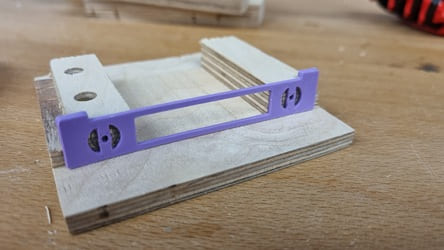
Some of the holes, particularly the ones on the base were not possible to be milled without creating a jig which was not sensible for just 8 holes. Therefore, I 3D printed a part which allowed me to mark where the threaded insert holes should be milled. It worked quite successfully but hand drilling holes will never be as accurate as CNC milling them.
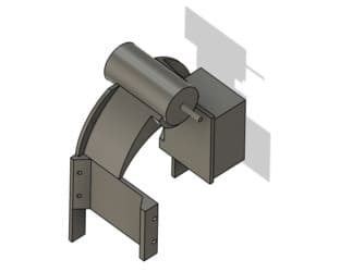
The Flyer and Bobbin
The flyer's main body was milled on the CNC router but it required a thread so I could also screw it onto the drum. The thread slides into the flyer's end and has two positive contacts sitting on a shelf on the inside and has a lip which covers the outside surface.
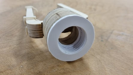
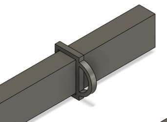
The other part which the flyer has is the wool guides which, as the name suggests, guide the wool to where you want it to wind onto the bobbin. They are very simple slides which have some flex parts which pinch down on the flyer to keep it in place. I printed these out of ASA due to their flexible nature.
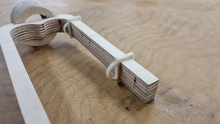
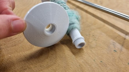
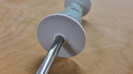
The bobbin is made up of a central tube which is quite a tight fit on the needle to help it not spin. On either end there are threads which allow the ends to screw on until they meet a lip which keeps them in place. These ends could be swapped for larger sizes in the future.
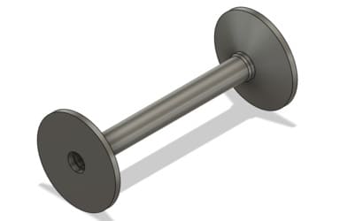
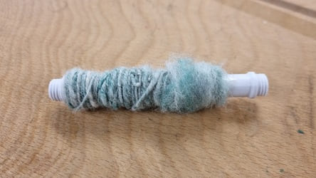
I also have made some gripper pieces which can be glued into the ends of the bobbin which are printed out of TPU. The tube is such a perfect fit that it is unnecessary but maybe be useful for slight variations in knitting needle thicknesses.
I created a file which contains all the PLA parts required all on one plate. They all fit onto the bed of a Prusa i3MK3s.