12. Input Devices
This week we are tasked with adding a sensor to a board we create and measure something using a input. For the spinning wheel we would like to create a controller which sits comfortably in the hand which has pressure controllers to change the speed and direction of the motor.
This would ideally be wireless which we will look at in more detail during newtworking week, so I will be making a PCB for a XIAO ESP32C3 which is capable of wifi and bluetooth.
Inspirations
I used Adrian Torres' documentation for help, who referenced Robert Hart's work.
I plan to use a lightweight foam inbetween the two copper layers to make up my built in pressure button.
Designing the Controller
Moulding
I started by using some oven bake clay to mold a ideal shaped controller for my hand and start planning the positions for my buttons.
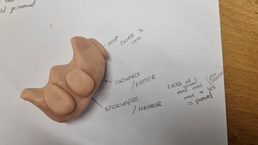
It has to be large enough to hold the XIAO and some PCB around it whilst fitting comfortably in the hand. It also had to allow the use of the thumb and index as they are key to spinning.
Photogrametry
The plan was to 3D scan the clay to have a 3D mesh I could model around however I came accross some issues. Our artec scanner was unable to be used as we had to update the software on the PC.
I then attempted photogrametry. I took about 180 pictures of the model from various angles then tried to use three different free softwares.
I think it was mainly the inconsistency in the photos but 3DF Zephyr and VisualSFM gave very bad results that weren't remotly useful. Meshroom was slightly more successful. I followed a tutorial by Sven Dännart which helped get some good starting settings, however I did have a lot of issues with it crashing during the DepthMap stage.
The model it produced was still quite disapointing however I had an attempt at fixing it in Meshmixer. This allowed me to smoothern things out but realistically it did not give a good fit without the need of lots of iterations.
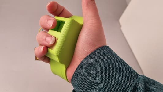
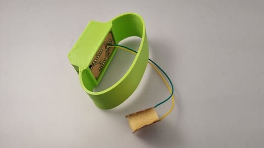
Band Version
I started making a simplified version where your hand would just sit in a band with the components inside of it. 3D printed out of flexible TPU.
I modelled and printed one draft version, however all the components stacked on on each other were too tall to comfprtably use the buttons.
Designing the PCB
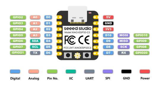
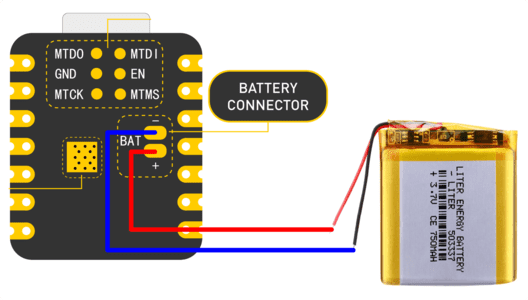
We are using the XIAO ESP32C3 at the main microcontroller. Mounting it to the board using some low profile throughhole headers. There are three input pads, one for a normal button switch and another two for where the copper pads will be wired to. I had to use one extra 0 ohm resistor to jump a wire.
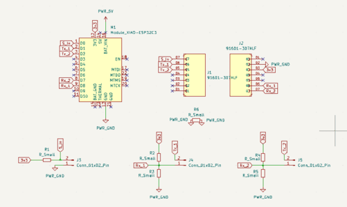
The XIAO has battery conector pads on it so they were not needed on the schematic.
I had some difficulty routing the wires. Initially I forgot to flip the XIAO to the other side of the board as we were using throughole headers so had to start again.
The second issue was a concern raised by John that the signal wire from input 1 should not pass through the center of the other input as this could cause affect the signals.
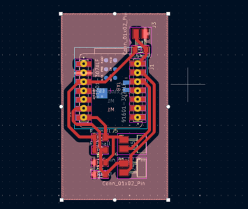
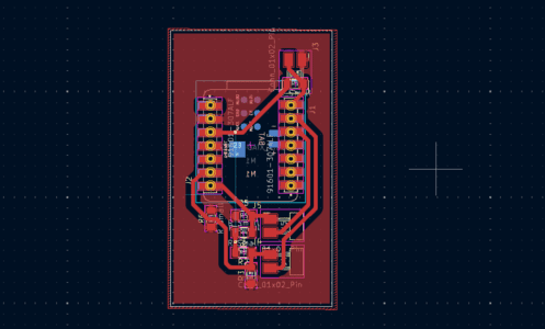
We did manage to find a good layout but we had to use a 0 ohm jumper resistor for the ground plain and a via to a wire on the back for the 3v3.
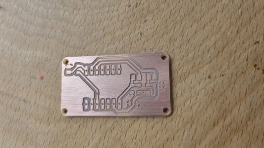
Milling
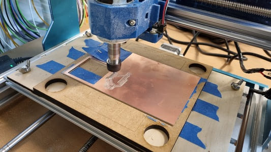
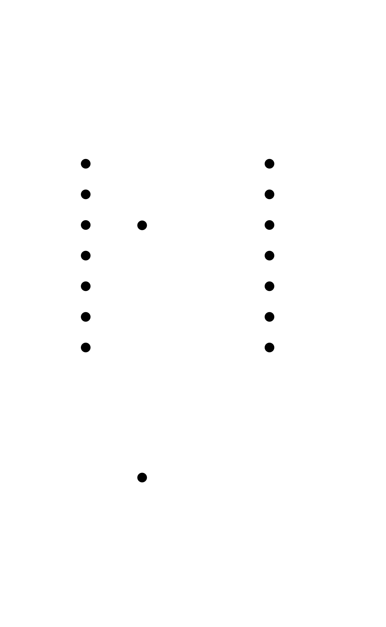
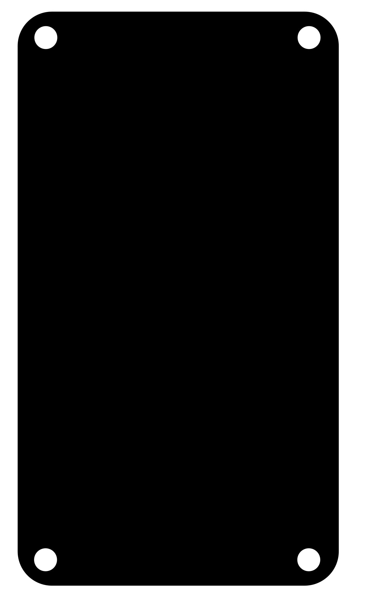
I exported the svgs from KiCAD into inkscape and started preparing them to be used to generate the milling paths. I seperate the files into traces, holes and outline cuts. I do this because we are using v-bits which are not very good at making these small throughhole holes. I therefore only make pilot holes using the CNC then finish them on the pillar drill.
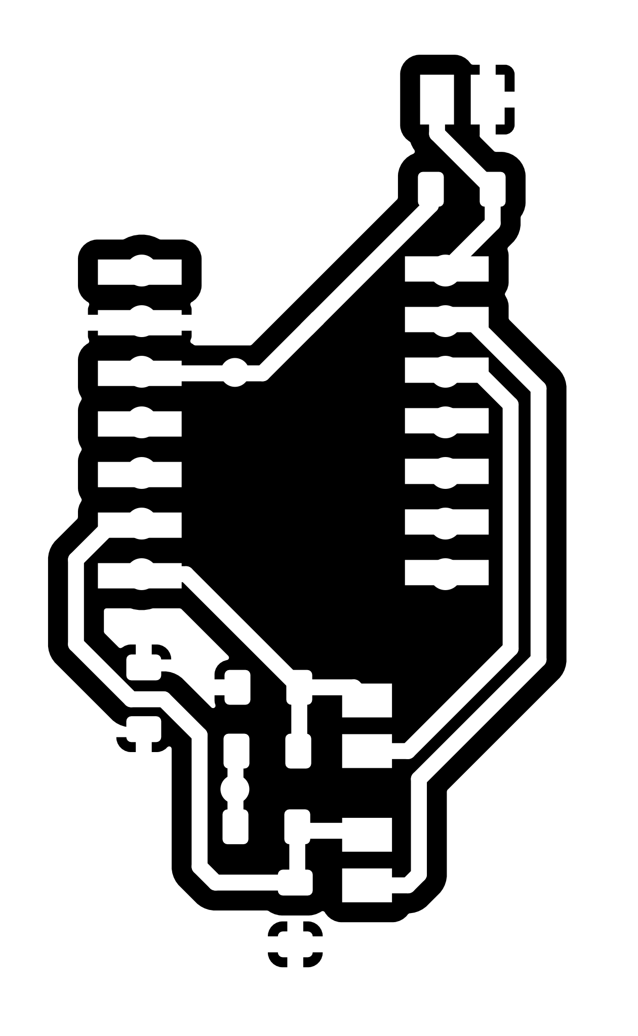
The current settings I use in Mods Projectfor the 3018 as as follows:
I then used the pillar drill to finish the holes.
Soldering
I started by soldering the resistors in the circuit. I used a 10k for the normal push button circuit and 4 1m ohm resistors for the copper pad inputs. Then there is the 0 ohm jumper.
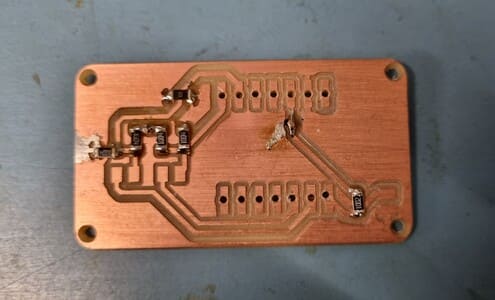
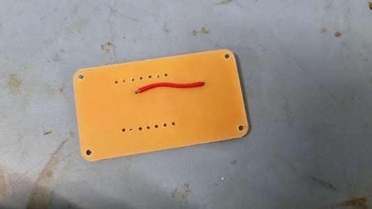
I then soldered the via wire connection on the back of the board. This was a bit tricky to do as there was not much copper left to solder to.
I then soldered the headers to the board and the pins to the XIAO.
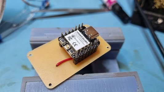
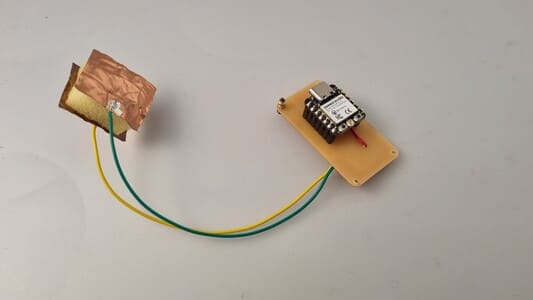
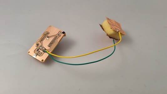
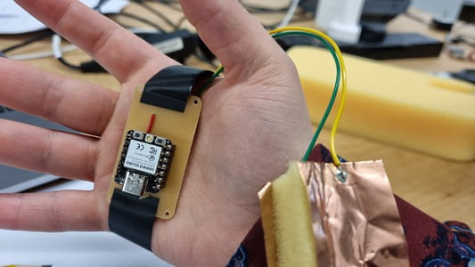
I then soldered some flywires to one of the pair of copper pad inputs and to two pieces of copper tape.
Coding
I set up the XIAO ESP32C3 following Seeed Studios getting started instructions.
I then used the code featured on Adrian Torres' page and just changed it for the pins I had designed for.
long result;   //variable for the result of the tx_rx measurement.
int analog_pin = 4;
int tx_pin = 20;
void setup() {
pinMode(tx_pin,OUTPUT);      //provides the voltage step
Serial.begin(115200);
}


long tx_rx(){         //Function to execute rx_tx algorithm and return a value
                      //that depends on coupling of two electrodes.
                      //Value returned is a long integer.
  int read_high;
  int read_low;
  int diff;
  long int sum;
  int N_samples = 100;    //Number of samples to take.  Larger number slows it down, but reduces scatter.

  sum = 0;

  for (int i = 0; i < N_samples; i++){
    digitalWrite(tx_pin,HIGH);              //Step the voltage high on conductor 1.
    read_high = analogRead(analog_pin);        //Measure response of conductor 2.
    delayMicroseconds(100);            //Delay to reach steady state.
    digitalWrite(tx_pin,LOW);               //Step the voltage to zero on conductor 1.
    read_low = analogRead(analog_pin);         //Measure response of conductor 2.
    diff = read_high - read_low;       //desired answer is the difference between high and low.
  sum += diff;                       //Sums up N_samples of these measurements.
  }
  return sum;
}                         //End of tx_rx function.


void loop() {

result = tx_rx();
result = map(result, 8000, 11000, 0, 1024);  //I recommend mapping the values of the two copper plates, it will depend on their size
Serial.println(result);
delay(100);
}
It outputted to the serial port numbers which changed depending on the amount of pressure you placed on the foam.
Conculsion
I had quite a few set backs this week. I wanted to make the controller fully however it did not work out.
I think realistically in my final project I will not use a hand held controller anyway but we will still use the XIAO ESP32C3's for networking within the machine itself.