9. Output Devices
This week we are exploring output devices with the aim of adding a motor to the motor driver board I made last week.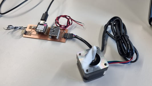
Lecture Notes
Safety
These devices require more current and voltage. This increases the concern for electrical safety.
Power supplies can store power in the capacitor for a long time so it is important to discharge the capacitor by holding something insulated e.g. screwdriver
Inductive flyback is where when a motor is switched off the magnetic field collapses releaseing a voltage which can blow components
You can use diodes in circuits to regulate voltage. MOSFET is a transistor which can control the flow of electricity, you want higher voltage for power, lower voltage for signals in the same circuit.
Power
USB normally 5v, USBPD can supply higher but only certain supplies. USBQC is a propriety protocol, quite widly supported, also reaches higher voltage.
lipos are the go to battery, need a module to handle the charge and discharge. Firehazard.
Switching power supplies - efficient but noisey. Linear - quieter but more expensive.
Magnetic field wireless transfer of power.
PWM
Stands for Pulse Width Modulation. We make pulses where we vary the duration, the width, but keep the frequency fixed. The voltage will also be fixed. You vary the fraction of on and off time to get varying results. This changes the duty.
A short pluse would be a dim LED, and a long pulse would be bright.
Coding with Outputs
I started by following guides within the Arduino Project Book as it allowed me to experience serveral inputs without needed to create a new board with each. It also gave me a taster before trying the actual project for this week - making my motor driver board work.
I found the guides very useful and clear. Using a breadboard was a new experience, I can understand why they are getting phased as it was being a bit flukey at times.
Arduino Uno with Servo
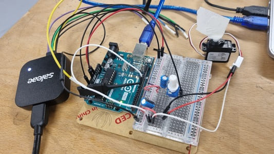
I started by setting up a circuit involving a servo. This should be helpful because BLDC moter use a ESC, electronic speed controller, which makes them act like a servo and I plan to use these in my final project.
This circuit uses a potentiometer so that the angle of the servo can be adjusted. As the knob is turned you change the ratio of voltage between the middle pin and power.
This can be seen in the recorded waves in Saleae.
The servo has 3 wires, power, ground and control.
The circuit utilised 100uf decoupling capacitors to smoothen out the voltage. This is because when the servo first moves it draws more current then if it was already in motion. The cathode is attached to ground, the anode to power.
There is code that posts the current angle to the serial port.
Here is the code that was provided:
#includeServo myServo; int const potPin = A0; int potVal; int angle; void setup() { myServo.attach(9); Serial.begin(9600); } void loop() { potVal = analogRead(potPin); Serial.print("potVal: "); Serial.print(potVal); angle=map(potVal, 0, 1023, 0, 179); Serial.print(", angle: "); Serial.println(angle); myServo.write(angle); delay(15); }
BLDC with H-Bridge
With motors if you swap the ground and power pins the motor moves in the oposite direction. If you want this to be built in to the circuit as a feature you use a H-Bridge.
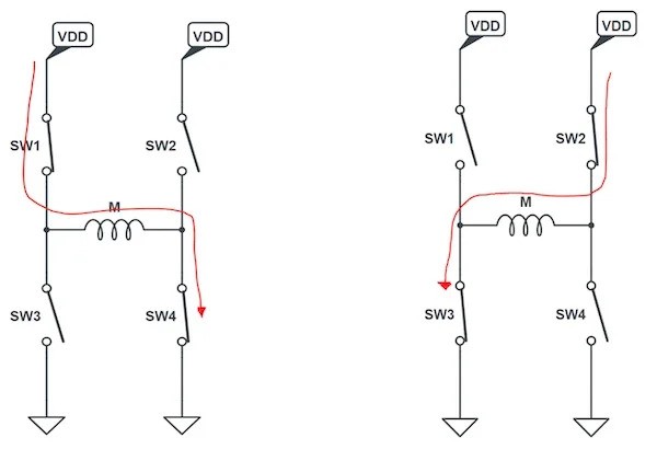
The H brdige uses switches to control the direction of power across the motor and therefore the direction it turns.
We wire this process to a button so easily switch the direction.
const int controlPin1 = 2;
const int controlPin2 = 3;
const int enablePin = 9;
const int directionSwitchPin = 4;
const int onOffSwitchStateSwitchPin = 5;
const int potPin = A0;

int onOffSwitchState = 0;
int previousOnOffSwitchState = 0;
int directionSwitchState = 0;
int previousDirectionSwitchState = 0;

int motorEnabled = 0;
int motorSpeed = 0;
int motorDirection = 1;

void setup() {
  pinMode(directionSwitchPin, INPUT);
  pinMode(onOffSwitchStateSwitchPin, INPUT);
  pinMode(controlPin1, OUTPUT);
  pinMode(controlPin2, OUTPUT);
  pinMode(enablePin, OUTPUT);

  digitalWrite(enablePin, LOW);
}

void loop() {
  onOffSwitchState =
    digitalRead(onOffSwitchStateSwitchPin);
  delay(1);
  directionSwitchState =
    digitalRead(directionSwitchPin);
  motorSpeed = analogRead(potPin) / 4;

  if (onOffSwitchState != previousOnOffSwitchState) {
    if (onOffSwitchState == HIGH) {
      motorEnabled = !motorEnabled;
    }
  }

  if (directionSwitchState != previousDirectionSwitchState) {
    if (directionSwitchState == HIGH) {
      motorDirection = !motorDirection;
    }
  }

  if (motorDirection == 1) {
    digitalWrite(controlPin1, HIGH);
    digitalWrite(controlPin2, LOW);
  }
  else{
    digitalWrite(controlPin1, LOW);
    digitalWrite(controlPin2, HIGH);
  }

  if (motorEnabled == 1) {
    analogWrite(enablePin, motorSpeed);
  } else {
    analogWrite(enablePin, 0);
  }

  previousDirectionSwitchState =
    directionSwitchState;
  previousOnOffSwitchState = onOffSwitchState;
}
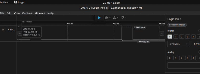
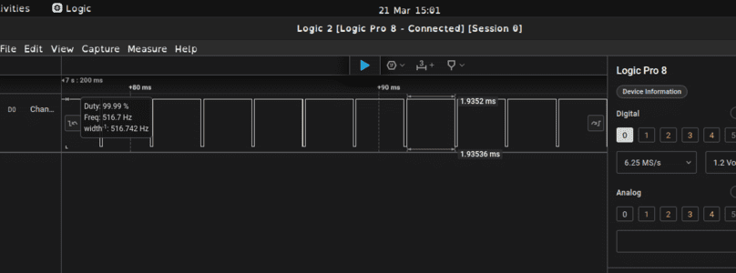
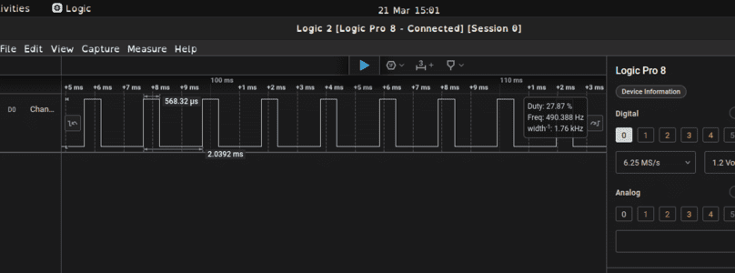
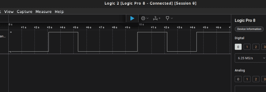
Here is the direction pulses on the Saleae.
You can see the speed change. When the duty is near 100% this is full speed. The minimum speed whilst still moving was around 30% duty.
Grove LCD
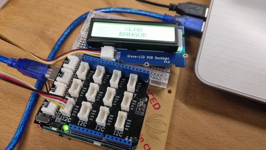
I then had a go with the Grove Starter Kit. Specifically the LCD Backlight Module.
Importing the wire.h and rgb_lcd.h required libraries did cause some problems as arduino failed to import all the examples but importing only the LCD example worked.
Here is the zip file that can be installed by going to Sketch > Install Library. See here for a guide.
Grove LCD zip#include#include "rgb_lcd.h" rgb_lcd lcd; const int colorR = 100; const int colorG = 0; const int colorB = 255; void setup() { // set up the LCD's number of columns and rows: lcd.begin(16, 2); lcd.setRGB(colorR, colorG, colorB); // Print a message to the LCD. lcd.print(" XLAB"); delay(1000); } void loop() { // set the cursor to column 0, line 1 // (note: line 1 is the second row, since counting begins with 0): lcd.setCursor(0, 1); lcd.print(" BANGOR"); delay(100); }
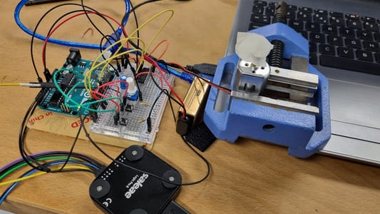
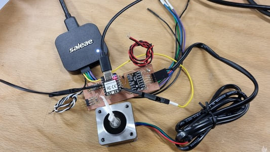
Stepper Motor Driver with XIAO RP2040
I hooked up my board I made last week to the stepper motor and a high power USB port.
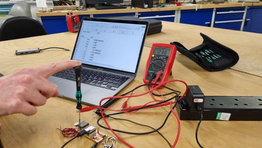
We had to adjust the vref of the motor driver board by using a screwdriver and a multimeter.
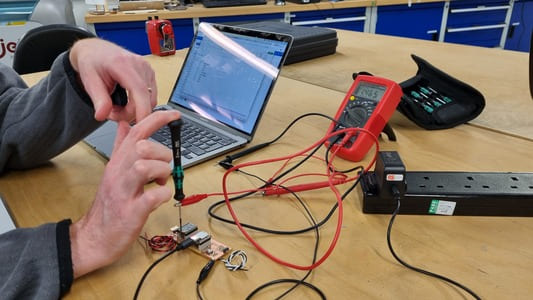
We are going to use a Oozenest Nema 14 and the vref should be in the range of 1.2-1.4v.
Found some starting code from How To Mechatronics. I addapted the code to have the correct pins. I also needed to set the enable pin to low as I believe this is the default for arduino boards.
I did initially get confused and read the wrong pins from my schematic but we debugged this.
Here is the code I used:
// defines pins
#define stepPin 2
#define dirPin 1
#define enPin 4

void setup() {
// Sets the two pins as Outputs
pinMode(stepPin,OUTPUT);
pinMode(dirPin,OUTPUT);
pinMode(enPin,OUTPUT);
}
void loop() {
digitalWrite(enPin,LOW); // Enables motor
digitalWrite(dirPin,HIGH); // Enables the motor to move in a particular direction
// Makes 200 pulses for making one full cycle rotation
for(int x = 0; x < 800; x++) {
  digitalWrite(stepPin,HIGH);
  delayMicroseconds(5000);    // by changing this time delay between the steps we can change the rotation speed
  digitalWrite(stepPin,LOW);
  delayMicroseconds(5000);
}
delay(1000); // One second delay

digitalWrite(dirPin,LOW); //Changes the rotations direction
// Makes 400 pulses for making two full cycle rotation
for(int x = 0; x < 1600; x++) {
  digitalWrite(stepPin,HIGH);
  delayMicroseconds(5000);
  digitalWrite(stepPin,LOW);
  delayMicroseconds(5000);
}
delay(1000);
}
I will now adapt the code so I can get the motor spinning as fast as possible by reducing the delayMicroseconds.
delayMicrosecond = 3000
delayMicrosecond = 1000
delayMicrosecond = 500
delayMicrosecond = 200. Too low.
delayMicrosecond = 300. Quite a bit of vibrations so I went a bit slower.
delayMicrosecond = 350. The motor doesnt seem to be struggling and it moves resonably fast. However, I am pretty sure this isn't fast enough for my project.
Button
We put a button on the board. I want to code this in order to switch the direction of the motor.
I attapted the button press code
It only stays in the reverse direction while the button is pressed.
const int buttonPin = 27;
#define stepPin 2
#define dirPin 1
#define enPin 4

// variables will change:
int buttonState = 0;  // variable for reading the pushbutton status

void setup() {
pinMode(buttonPin, INPUT);
pinMode(stepPin,OUTPUT);
pinMode(dirPin,OUTPUT);
pinMode(enPin,OUTPUT);
}

void loop() {
digitalWrite(enPin,LOW); // Enables motor

buttonState = digitalRead(buttonPin);

// check if the pushbutton is pressed. If it is, the buttonState is HIGH:
if (buttonState == HIGH) {
  digitalWrite(dirPin,HIGH);
  digitalWrite(stepPin,HIGH);
  delayMicroseconds(350);
  digitalWrite(stepPin,LOW);
  delayMicroseconds(350);

}

else {
  digitalWrite(dirPin,LOW);
  digitalWrite(stepPin,HIGH);
  delayMicroseconds(350);
  digitalWrite(stepPin,LOW);
  delayMicroseconds(350);

}
}
I addapted the interupt code.
This code does allow for a constant switch of direction.
volatile bool dirState = false;
const int interruptPin = 27;
#define stepPin 2
#define dirPin 1
#define enPin 4

void setup() {
pinMode(stepPin,OUTPUT);
pinMode(dirPin,OUTPUT);
pinMode(enPin,OUTPUT);
pinMode(interruptPin, INPUT);
attachInterrupt(digitalPinToInterrupt(interruptPin), switchPressed, RISING);
}

void loop() {
digitalWrite(enPin,LOW); // Enables motor
digitalWrite(dirPin, dirState ? HIGH : LOW); // Enables the motor to move in a particular direction
  digitalWrite(stepPin,HIGH);
  delayMicroseconds(350);
  digitalWrite(stepPin,LOW);
  delayMicroseconds(350);
}

void switchPressed(){
dirState = !dirState;
}
State Machine
We set up a enumerator that has the two states I need for my motor, clockwise and counter clockwise, and then set the starting direction to be clockwise.
State machines are useful to enforce a waiting period and to only allow operations to occur within certain states.
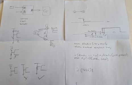
Button press is causing a change in the state of the motor.
enum directions { CW,
  CCW };
volatile directions direction = CW;
const int interruptPin = 27;
#define stepPin 2
#define dirPin 1
#define enPin 4

void setup() {
pinMode(stepPin, OUTPUT);
pinMode(dirPin, OUTPUT);
pinMode(enPin, OUTPUT);
pinMode(interruptPin, INPUT);
attachInterrupt(digitalPinToInterrupt(interruptPin), switchPressed, RISING);
digitalWrite(enPin, LOW);
}

void loop() {
if (direction == CW) {
digitalWrite(dirPin, HIGH);
} else {
digitalWrite(dirPin, LOW);
}
digitalWrite(stepPin, HIGH);
delayMicroseconds(350);
digitalWrite(stepPin, LOW);
delayMicroseconds(350);
}


void switchPressed() {
if (direction == CW) {
direction = CCW;
} else {
direction = CW;
}
}
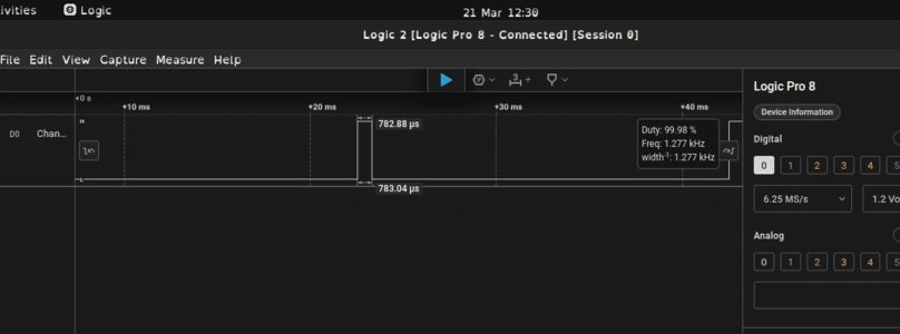
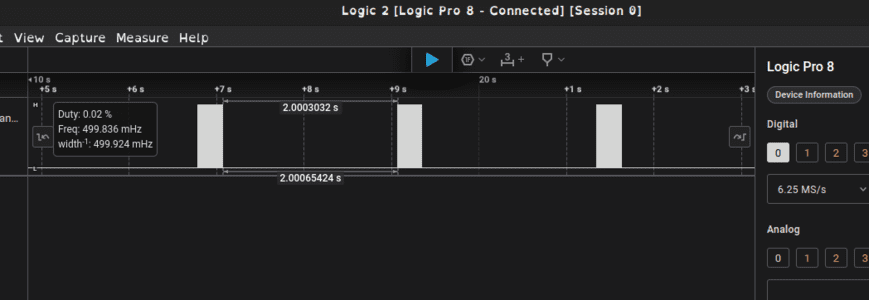
Proof its halfstepping, 400 steps = 1 full rotation
We had hardwired the driver board so that it did the largest steps possible, which was the halfstep. We did this because we wanted as much speed as possible.
In order to confirm this I set up the motor to turn the 400 steps which should be a full circle.
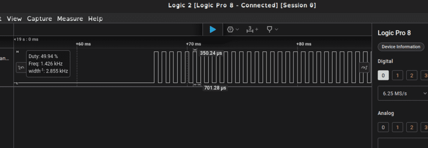
I also connected it to the Saleae where you can see that the motor is at 50% duty as it is on and off some the same amount of time, 350 microseconds.
You can see here the gap between the pulses are 2 seconds.
enum directions { CW,
  CCW };
volatile directions direction = CW;
const int interruptPin = 27;
#define stepPin 2
#define dirPin 1
#define enPin 4

void setup() {
pinMode(stepPin, OUTPUT);
pinMode(dirPin, OUTPUT);
pinMode(enPin, OUTPUT);
pinMode(interruptPin, INPUT);
attachInterrupt(digitalPinToInterrupt(interruptPin), switchPressed, RISING);
digitalWrite(enPin, LOW);
}

void loop() {
if (direction == CW) {
digitalWrite(dirPin, HIGH);
} else {
digitalWrite(dirPin, LOW);
}
for (int x = 0; x < 400; x++) {
digitalWrite(stepPin, HIGH);
delayMicroseconds(350);
digitalWrite(stepPin, LOW);
delayMicroseconds(350);
}
delay(2000);
}


void switchPressed() {
if (direction == CW) {
direction = CCW;
} else {
direction = CW;
}
}
Saleae videos
Saleae connected to Direction Pin
Saleae connected to Step Pin