6. Embedded Programming
write a program for a microcontroller development board that you made, to interact (with local input &/or output devices) and communicate (with remote wired or wireless devices) extra credit: use different languages &/or development environments extra credit: connect external components to the board
Architectures
Computer architecture refers to the design, structure and functioning of a computer system. It focuses on how various components, such as the processor, memory and input/output (I/O) devices, interact and perform tasks efficiently.
There are two architectures (source):
Because memory can only be accessed once per clock cycle, in principal a Von Neumann architecture requires at least two clock cycles to execute an instruction, whereas a Harvard architecture can execute instructions in a single cycle. Therefore Harvard is more commonly used.
CISC vs RISC Instruction Sets
CISC - Complex Instruction Set Computers
CISC's main aim is to complete a task in as few lines of assembly as possible by using complex instruction to do so.
RISC - Reduced Instruction Set Computers
RISC only uses simple instructions that can be executed within one clock cycle using more lines of assembly.
RISC is the commonly used one because each instruction requires only one clock cycle to execute, the entire program will execute in approximately the same amount of time as the multi-cycle "MULT" command. These RISC "reduced instructions" require less transistors of hardware space than the complex instructions, leaving more room for general purpose registers. (Source)
Microcontrollers and Microprocessors
A microprocessor is powerful, but requires seperate chips surrounding it for memory, communication etc.
A microcontroller is less powereful however all the chips are a part of it. It is a complete package.
We will use Harvard architecture, RISC instruction sets and microcontrollers.
Memory
Peripherals
How the processor talks to the world around it:
Word size
How much information the processor can read at the same time. 8, 16, 32, 64. Simpilist microprocessors use 8bit, more complex ones up to 32bit. Computers use 64bit. An a 8bit processor can work on 64bit data, it just takes some more instructions. The 8bit processors can be faster and cheaper.
Processor Families
AVR - 8 bit processors. Some notible sizes:
ARM - Designs processor infrostructure. Many companies use the designs.
Xtensa
RISC-V
Packages
You can buy the processors in many different packages. Some are easier to handle and solder than others.
Vendors
Embedded languages
You can program at different levels but it all gets translated to hex
Assembley - Fastest, most efficient but difficult to write, specific to processor
C, C++ - Most commily used. Easy to make security vulnerabilities. The language behind Arduino.
Rust - Improved version of C.
Python - Interpretated (slower). Interactive. Micropython, circuit python.
In system development
Connect to the processor to transfer the code.
Development enviroments
Codeing the RP2040
Did some coding to interact with the XIAO Seeed on the quentorres board we made during week 4.
Arduino
It is useful to have both versions of the Arduino installed as the AVRs only work well with the original IDE. Modern kit probably works best in Arduino v2.
Button
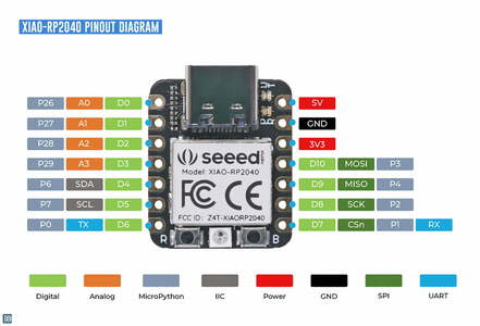
I started by editing the example code from using a button. I only had to look at the XIAO pin descriptors and compare to my board to see which pins to use.
// constants won't change. They're used here to set pin numbers:
const int buttonPin = 27;  // the number of the pushbutton pin
const int ledPin = 26;    // the number of the LED pin

// variables will change:
int buttonState = 0;  // variable for reading the pushbutton status

void setup() {
  // initialize the LED pin as an output:
  pinMode(ledPin, OUTPUT);
  // initialize the pushbutton pin as an input:
  pinMode(buttonPin, INPUT);
}

void loop() {
  // read the state of the pushbutton value:
  buttonState = digitalRead(buttonPin);

  // check if the pushbutton is pressed. If it is, the buttonState is HIGH:
  if (buttonState == HIGH) {
    // turn LED on:
    digitalWrite(ledPin, HIGH);
  } else {
    // turn LED off:
    digitalWrite(ledPin, LOW);
  }
}
Debounce
When a button is pressed the signal goes from low to high. However this isn't usually a clean change. The signal may bouce between the the two level for a bit. This can cause a flicker in the LED or more importantly, if you are counting the number of times a button goes high this can sque the count.
You can set up a buffer period that starts after the fist high detection. During this time it will ignore any signals. After this period passes it reads the buttons situation again. If it's still high it is counted or if it is now low it is disregraded.
Used the default example code and edited it to match my board.
// constants won't change. They're used here to set pin numbers:
const int buttonPin = 27;  // the number of the pushbutton pin
const int ledPin = 26;    // the number of the LED pin

// Variables will change:
int ledState = HIGH;        // the current state of the output pin
int buttonState;            // the current reading from the input pin
int lastButtonState = LOW;  // the previous reading from the input pin

// the following variables are unsigned longs because the time, measured in
// milliseconds, will quickly become a bigger number than can be stored in an int.
unsigned long lastDebounceTime = 0;  // the last time the output pin was toggled
unsigned long debounceDelay = 50;    // the debounce time; increase if the output flickers

void setup() {
pinMode(buttonPin, INPUT);
pinMode(ledPin, OUTPUT);

// set initial LED state
digitalWrite(ledPin, ledState);
}

void loop() {
// read the state of the switch into a local variable:
int reading = digitalRead(buttonPin);

// check to see if you just pressed the button
// (i.e. the input went from LOW to HIGH), and you've waited long enough
// since the last press to ignore any noise:

// If the switch changed, due to noise or pressing:
if (reading != lastButtonState) {
  // reset the debouncing timer
  lastDebounceTime = millis();
}

if ((millis() - lastDebounceTime) > debounceDelay) {
  // whatever the reading is at, it's been there for longer than the debounce
  // delay, so take it as the actual current state:

  // if the button state has changed:
  if (reading != buttonState) {
    buttonState = reading;

    // only toggle the LED if the new button state is HIGH
    if (buttonState == HIGH) {
      ledState = !ledState;
    }
  }
}


// set the LED:
digitalWrite(ledPin, ledState);

// save the reading. Next time through the loop, it'll be the lastButtonState:
lastButtonState = reading;
}
The button switches the state of the light to the oposite state.
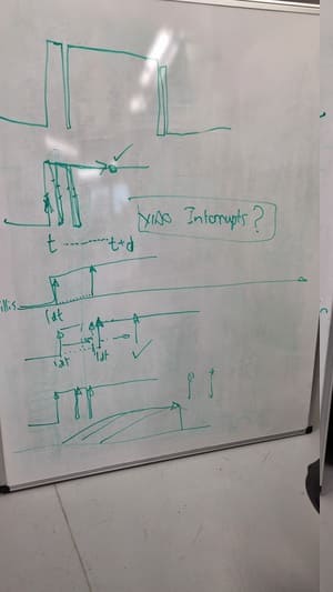
Interupt
An interupt is a an event that alters the sequence in which the processor executes instructions. It basically jumps in, puts everything on hold, runs its code, then allows the processor to continue from where it was.
This is very useful when you want the processor to react to a certain event such as a signal. However, this stop the running of other processors such as the clock so you want the interupt code to be as lightweight as possible so it isn't stuck doing the interupt code for long.
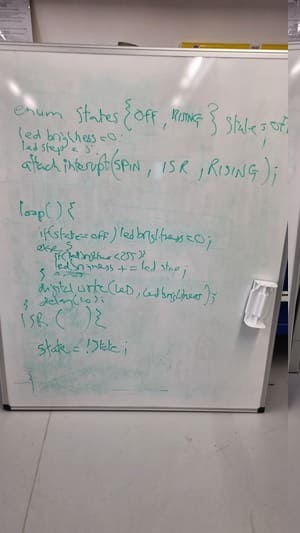
We mostly wrote our own code this time but got the base from this post.
volatile bool ledState = false;
const int interruptPin = 27;
const int LED = 26;

void setup() {
  pinMode(interruptPin, INPUT);
  pinMode(LED, OUTPUT);
  attachInterrupt(digitalPinToInterrupt(interruptPin), switchPressed, RISING);

}

void loop() {
  digitalWrite(LED, ledState);
  delay(10);
}

void switchPressed(){
  ledState = !ledState;
}
The code by default is just running the LED but it is interupted by a button push which switches the state of the LED. This is different to the other code because the processor isn't constantly checking for a change in button. Makes a cleaner and short code but looks the same.
The button switches the state of the light to the oposite state.
Thonny
We then did a bit of coding using Thonny and micropython. The Seeed XIAO website had a tutorial that we started following to set it up.
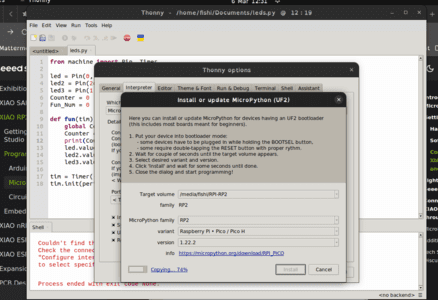
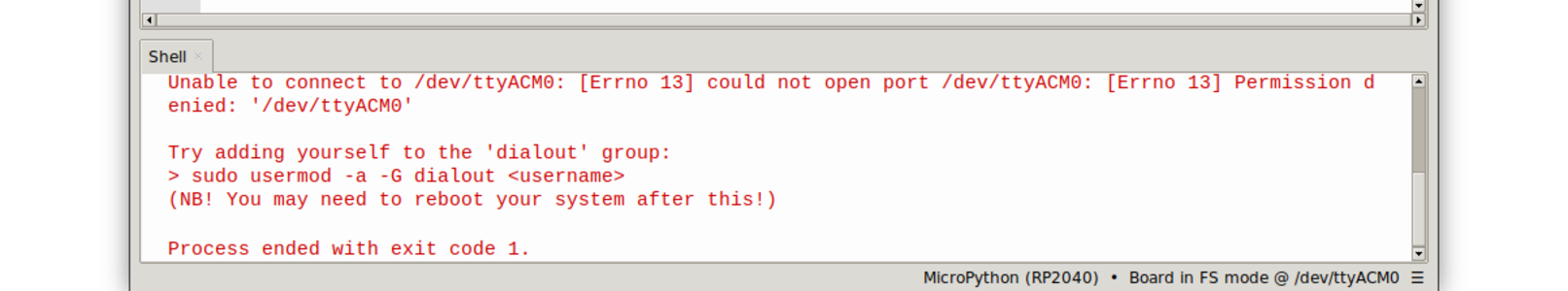
We had some issues setting up the RP2040. I had to add myself to the dilout path before I could connect to the board.
We then used the basic blink code example.
from machine import Pin, Timer

led = Pin(26, Pin.OUT)
Counter = 0
Fun_Num = 0

def fun(tim):
    global Counter
    Counter = Counter + 1
    print(Counter)
    led.value(Counter%2)

tim = Timer(-1)
tim.init(period=1000, mode=Timer.PERIODIC, callback=fun)
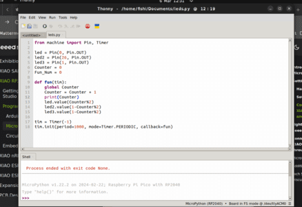
I then edited it to use all 3 leds and make them blink at different times.
from machine import Pin, Timer

led = Pin(0, Pin.OUT)
led2 = Pin(26, Pin.OUT)
led3 = Pin(1, Pin.OUT)
Counter = 0
Fun_Num = 0

def fun(tim):
    global Counter
    Counter = Counter + 1
    print(Counter)
    led.value(Counter%2)
    led2.value(1-Counter%2)
    led3.value(1-Counter%2)

tim = Timer(-1)
tim.init(period=1000, mode=Timer.PERIODIC, callback=fun)
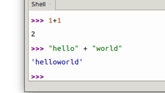
Then also did the basic test communication with the processor through the REPL.
Coding the microBit
The microbit is a beginners coding board originally created by the BBC to be used in schools. It has a intergrated Nordic nRF52833 processor, a LED array, several buttons, sensors and IO pins.
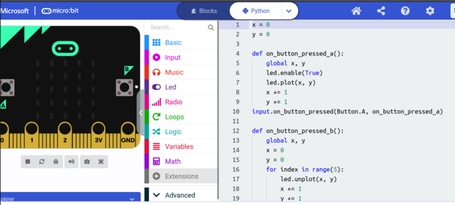
Microsoft MakeCode
The standard editor used is made by Microsoft MakeCode and it gives the options of using blocks, python or Java.
I made a basic block code program to interate through the grid and turn on a LED.
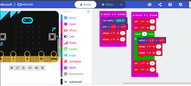
You can see it converted to python as well.
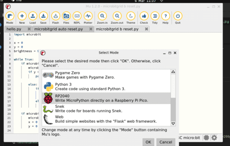
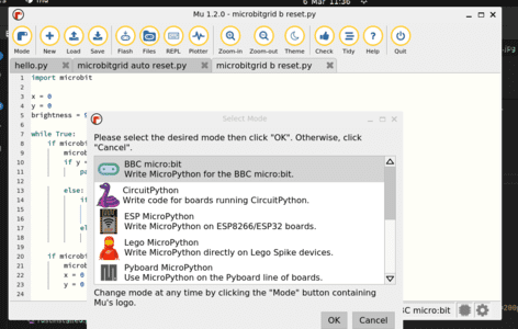
Mu
Mu is a python editor. It can be downloaded hereI liked how it detected the board and automatically switched modes bwteeen the Microbit and the RP2040.
You can use MicroPython to code either of the two. We decided to code the microbit some more to do a similar task as what the block code did.
The Microbit Micropython documentation was very helpful at getting it working.
I started off small just turning on a single led.
import microbit

while True:
    if microbit.button_a.is_pressed():
        microbit.display.set_pixel(0, 0, 9)
    else:
        microbit.display.set_pixel(0, 0, 0)
Then we made it more complex making the led grid possition change so the leds were turned on in rows.
I couldnt figure out how to make it clear the screen when it reached the end so I used the B button initially.
import microbit

x = 0
y = 0
brightness = 9

while True:
    if microbit.button_a.was_pressed():
        microbit.display.set_pixel(x, y, brightness)
        if y == 4 and x == 4:
            pass

        else:
            if x == 4:
                x = 0
                y += 1
            else:
                x += 1

    if microbit.button_b.was_pressed():
        microbit.display.clear()
        x = 0
        y = 0
John then helped me design a version which auto reset when it had filled the grid.
import microbit

x = 0
y = 0
allset = False

while True:
    if microbit.button_a.was_pressed():
        if allset:
            microbit.display.clear()
            allset = False
            x = 0
            y = 0
        else:
            microbit.display.set_pixel(x, y, 9)
            if y == 4 and x == 4:
                allset = True

            else:
                if x == 4:
                    x = 0
                    y += 1
                else:
                    x += 1
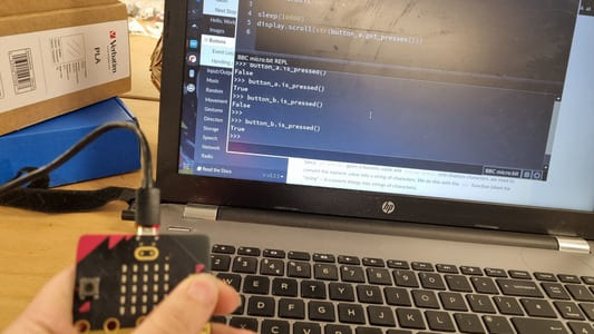
You could also use the REPL in MU to speak to the processor.
Rust
I made an attemt at setting Rust up following the instructions from the instructor bootcamp however They ended up not working.
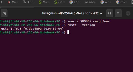
I successfully installed rust itself.
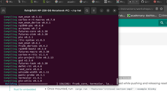
I then started installing the neccessary libraries.
However, when I come to run the example code it is not found.
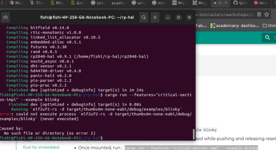
We decided to leave it there as it is a bit to complex for a biginner coder anyway.