5. 3D Scanning and Printing
This week we are looking at the processes of 3D printing and 3D scanning
Last we we looked at the subtractive process of PCB milling, this week we are looking at the additive process of 3D printing.
Additive Processes Benefits:
Class Notes
3D printing has a lot of parts and settings that could cause issues with the print. simplify3d and matterhackers have useful troubleshooting guides.
Some of the main issues are:
A lot of these issues can be caused in many ways and often the troubleshooting stage of setting up a 3D printer can be too frustrating. However, things have much improved with some pre-built machines being very reliable and problems well documentaated. A large part of the community is 'hacking' your printer to improve its preformance but that is not for everyone.
When I first brought my Prusa i3 MK3S+ secondhand I had a lot of issues with prints not sticking, trying many fixes until I finally discovered that some of the screws had come loosen on the base plate making it rattle and hard to print on.
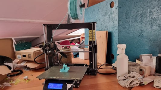
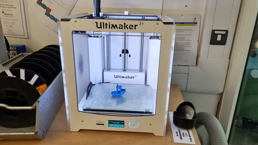
Printing test models specifically designed to demonstrate the limits of your machine and material choice are usful to characterise what is possible and whether teaking certain settings is beficial. Tried some of these prints on the
FDM vs SLA
The most common hobbiest 3D printers are fused deposition modeling (FDM). They use rolls of plastic fillament which is melted and layed down in layers to build up the final piece. This tend to leave noticible layer lines, however they can be quite fast and useful for prototyping and quick fixes.
SLA (Stereolithography) printers use UV curing resin which is exposed to UV in the required area to build up one layer at a time. They are popular within minature creation fanbases due to the high resolution that is possible making layer lines less visible. However the resin is toxic and messy to deal with in comparrision to FDM.
Material Choices
There are many options of FDM fillament available these days varying properties. Zack Freedman has a four part video series on all the types of materials he could get his hands on which is a interesting watch. Part 1 Part 2 Part 3 & Part 4.
The most common ones are below:
Material Storage
It is recommended to store your filament in sealed bags or containers with silaca gel to prevent the filament to becomming moist as many plastic aree hygroscopic.
Moist filament can cause print issues such as stringing and clogging. It can sometimes be seen by bubbles forming in the extruded filament from where the water has been heated to steam.
In most cases you can dry out the filament with a filament dryer box or low-temerature oven, however there is a point where too much damage is done to the filament.
Safety
As memtioned above, some materials release toxic fumes when melted, therfore it is recommended to have a enclosed printing case and extraction to deal with them.
Another safty aspect to consider it that the bed and nozzel get up to high temperatures. Even PLA which is quite low use about 190 degrees c nozzel and 60 degrees c bed temperature. Therefore burns can be a hazzard.
As the printer is moving there is always the risk of entrapment. Do not put your hand inside the machine whilst it is printing.
As a sidenote - 3D prints are not food safe. Even if you use a foodgrade plastic the set up of the printer and residue from previous plastic makes it very hard to control.
Model Design Considerations
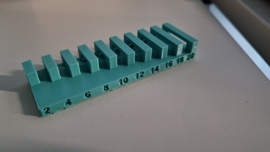
When 3D modelling it is good practice to avoid steep overhangs. From the tests we found around 30 degrees in the maximum before it starts deforming too much. If possible build in fillets or chamfers.
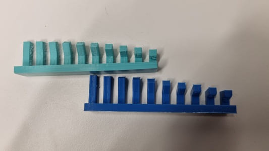
You also want to avoid too large a bridgeing section or you will be forced to use supports.
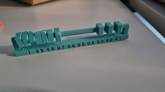
You will need to build in some clearance to fitted parts. With laser cutters you need to add material to deal with kurf, 3D prints need to be designed slightly smaller than the desired finished size. Around a 0.4mm gap.
With 3D prints the weak sections will always be the layers. Therefore if good to consider which parts of the model need to run horrizontal to bed in order to give them the most mechanical strength possible. For example if you are printing a tall cillinader you want in laying down on the bed instead of virtically.
Inside and outside dimentions will need to be compensated for as well and the layerlines add some extra friction which can prevent things fitting.
The amount you need to compensate for depend on the material and the printer. So it is worth to run some tests before committing to a large print.
Slicing
3D printing relies on slicing a model into layers which it will then print.
There are many softwares availble and most printers have one which is recommended, but they mostly all work in a similar fashion.
I use the following for the 3D printers I have access to:
It is in the slicer where you adjust the majority of the print settings. Here are a few main settings:
It can be daunting to consider all the options and a lot of these settings can cause issues in the print if set incorrectly. However, most slicer have preset values which tend to work well for the standard filaments.
Post Processing
Certain filaments can be smoothed over using acetone. Overwise you can normally sand the plastic down to the desired finish.
SLA prints need to be washed in isopropil alcohol then have a final cure with a UV light.
Any supports and brim need to be removed. Some clippers or pliers work well, however there is still normally some roughness left over.
Some interesting topics
Some 3D printers are being released with Klipper > software. This allows the software to 'learn' and speed up a printers speed overtime with the addition of a microcontroller to do the computing.
Printing in 3D printing in non-plastic materials have been developing. There are now options for printing in metal, concreat, chocolate and biological material. Although not at the hobbiest level yet.
There are more cominly dual-head printers available which can switch types of plastic during the layers allowing complex multicolour prints.
Creating a 3D Printed Project
When first starting to brainstorm project ideas I wanted to have something that incorperated multiple materials, TPU and PLA and some sort of hinge which allowed the PLA to flex with the TPU.
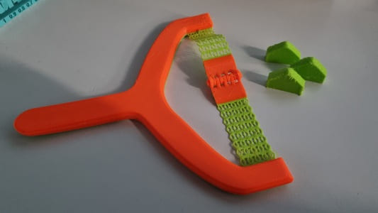
We considered creating a speaker would be cool but too much of a project for one week. A alternative that we decided on was a print-in-place slingshot that incorperated a TPU printed band.
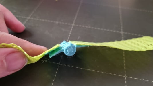
The first thing I needed to test is how the thickness of the TPU affects the flexability. I also wanted to see if there was a specific infill patten which stretched nicely.
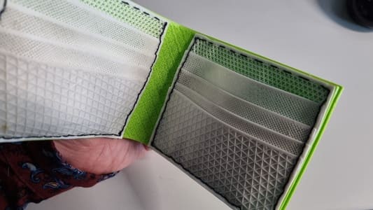
In the past I had experimented with 'TPU fabric' by finding a set of instructions for a leather wallet. Recreating the parts as a 3D model then when it came to slice them setting the top and bottom thicknesses to 0. This essentially gave a print that included only infill and walls. For the wallet this was just for aesetic reason but I want to use it to increase the stretch this time round.
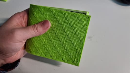
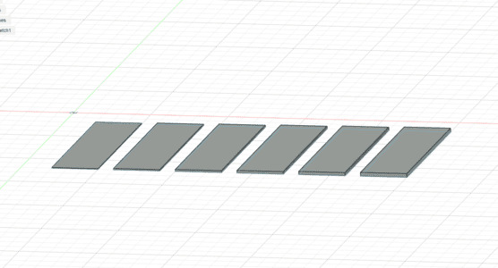
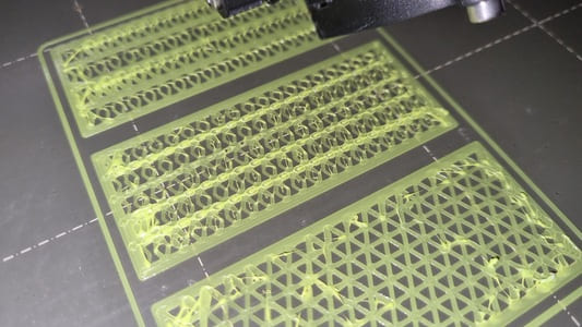
I created some very simple rectangles in fusion and extruded them up to verying heights: 0.2, 0.4, 0.6, 0.8, 1.0, 1.2. I chose these numbers because I usually print with a 0.2mm layer height and therefore that is testing 1-6 layers.
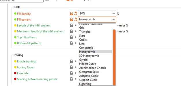
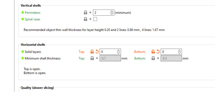
In Prusa Slicer I improted the STL. Went to print settings and set top and bottom thickness to 0. Under infill pattern I looked through to find the ones most likly of succeeding. I also sliced one which was 100% as a control.
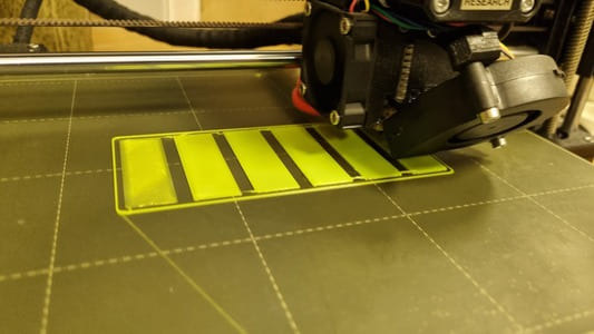
In conclusion 0.6mm thickness, 3 layers, was the best thickness of TPU for this application. Any thinner deformed too easily and and those thicker were starting to get hard to stretch.
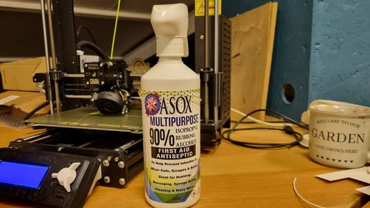
One useful tip to remove the thin TPU from the the buildplate is to spray with isopropil alcohol. I normally use it to clean the bed but it is a good release agent.
In terms of infill a pattern did seem to extend the stretch, however there wasn't a clear outlier. I also realised when I printed in place the final project I wanted top and bottom layers on the other sections so using the infill method was not really viable.
I decided I would need to model a custom pattern.
Meta Materials
One interesting topic that was brought up was meta materials.
Metamaterials derive their properties not from the properties of the base materials, but from their newly designed structures. Their precise shape, geometry, size, orientation and arrangement gives them their smart properties
I wouldn't be going to the extent of trying to change the base makeup of the material and I would take advantage of the TPU properties. However the patterns gave me inspiration for the design I would implement.
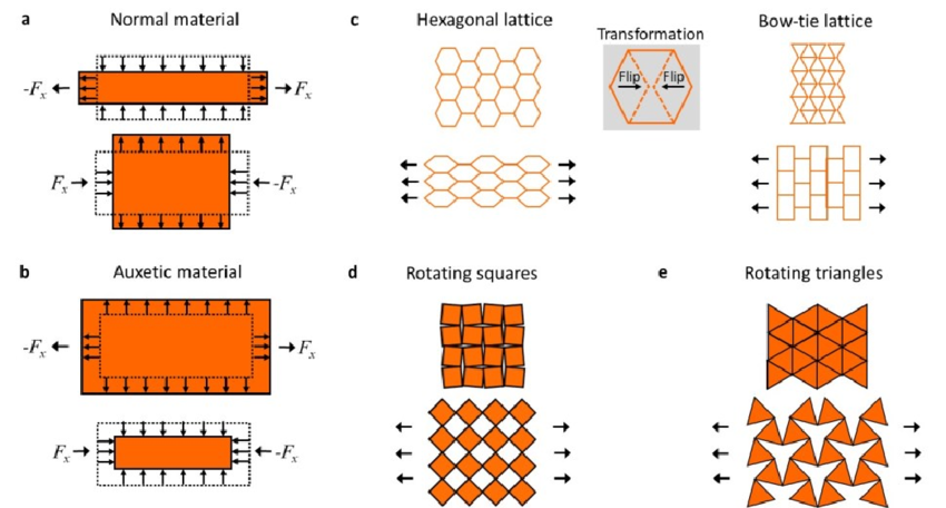
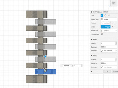
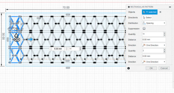
I practiced modelling some patterns to find the best way to create the repeating designs. The 'rectangular pattern' worked well for streight line patterns but there wasnt an option to rotate them or repeat the pattern along a path.
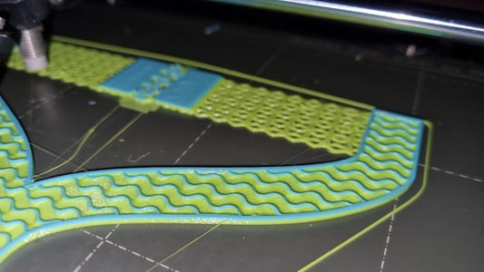
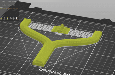
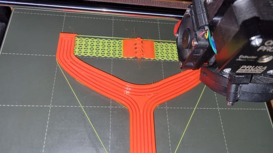
Version 1 - Does it stick
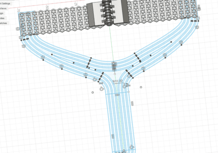
I opted for the 'bow-tie lattice'. I sketched out the first piece of the pattern that would be repeated, then I copied the pattern for the next row which was moved diagonally offcenter. I then used the retangular pattern to repeat it down and across a few more times.
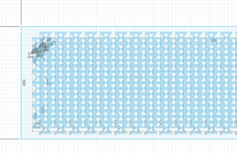
As I used the offset line tool this caused a long of unnceccessary lines which made the program run slow. It was also a hassle to select the sections I needed to extrude due to my computer struggling and lagging and how many small sections there was to click.
I then mirrored the band so it would make the other half.
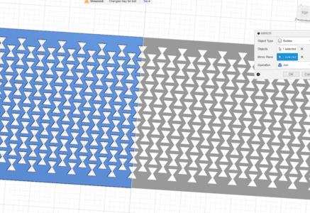
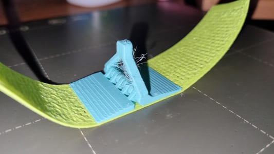
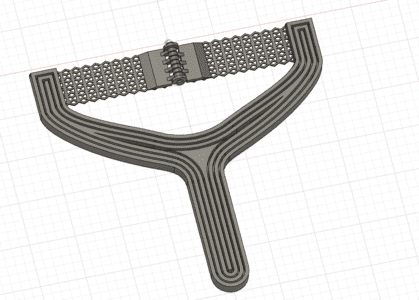
Afterwards I started modelling the hinge which would hopfully grab onto the ammo and give the user something sturdy to pull back on.
Seeing how well the TPU attached to the PLA was also part of this test so I didnt make the handle as that would potentially waste a decent amount of fillament.
Review on Version 1:
Version 2 - Which pattern
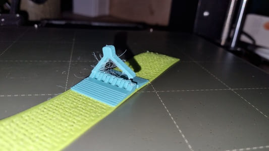
I went about fixing the issues by first redesigning the band pattern. I used a couple different sizes of the pattern. I did make a mistake which meant the 'bow' meta pattern was replaced with dimonds. I had forgotton to offset the bow on each line so it fit like a lattice, I ended up with rows of bows, however if stretched in the other direction I had dimonds flexing and stretching to make streight lines.
I also on a whim designed one with repeating triangles.
Review on version 2:
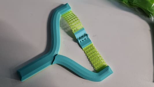
Version 3 - Pattern with hinge
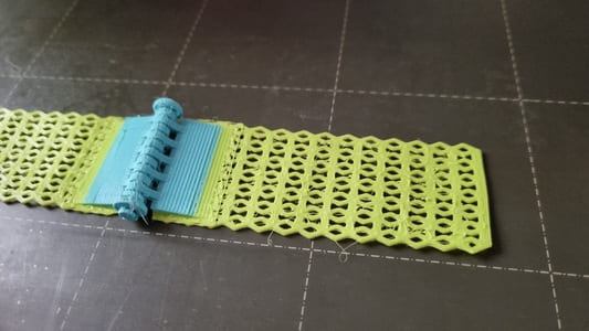
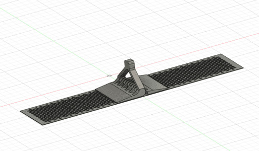
I modified the pattern to include the dimonds, I split the band into two halves. I also removed the supporting horrizontal bands at the top and bottom as it was limiting the stretch and I believe it is strong enough without them.
When I sliced it I raised the material switch up higher so the bottom of the hinge section was TPU as well.
Review of version 3:
Version 4 - Handle time!
I started off by reducing the number of dimonds to thin the band. I had to make the hinge shorter as well to match. I then sketched out a shape for the handle. I used mirror to make sure both sides were symetrical. The ends overlapped with the band to make a strong bond. I chamfered some of the sides so it would be nice to hold.
Review of version 4:
John suggested I add gaps in the handle to essentially force the printer to add more walls in the middle which would strengthen them. I can then add solid top and bottom surfaces to stablise them.
I printed some test pieces, however they all seemed about equally strong. I quite likey the idea on the walls as they gave strength to the part in the right directions.
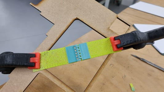
Version 5 - Final
I did some final reworking to the model. At this point I would just remake it as going and editing the history too much can mess with features down the timeline, however due to time limitations I just made it work.
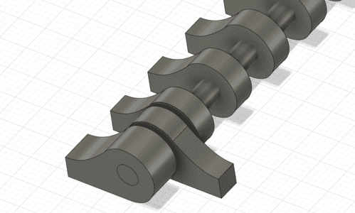
I 'broke' apart some of the overlapping splines that made up the handle so they connected fully. This then allowed me to offset the outside line to create the inner walls.
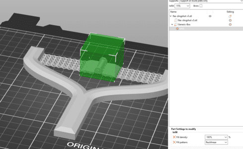
I extruded 2mm thickness base, 7mm for the wall exctions, then 2mm on top layer to encase them.
When slicing I still swapped to the second material a bit into the connector area. I also used a motifier to ensure it was 100% infill in that area. I then set the infill of the rest of the model to 50%, although a lot of this was already just wall like we modelled.
I then sliced it at 0.2mm layer height.
Results:
3D Scanning
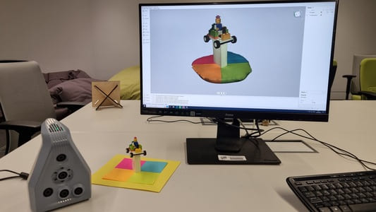
In our workshop we are lucky to have a Artec Space Spider 3D scanner. It has a 3D point accuracy up to 0.05mm and a 3D resolution of 0.1mm. It is handheld and requires a resonably beefy computer to run the software which will process the features the scanner captures.
It took a bit of getting use to but I managed to get a good result from the scan.
Main things to consider:
We had some issues exporting the files from the software as I was trying to save directly to my pen drive which kept failing. This meant I lost the 3D files of my first attampt but I have some pictures.
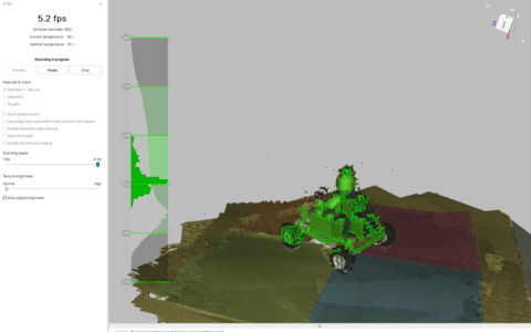
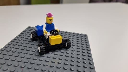
We decided a lego build would be quite a good subject to be scanned. There was a small piramid in the box which I began with but it was struggling to keep the orientation correct. This is also because I kept accidently losing the model by being too close. As it was such a regular shape it was difficult for the software to align the scans correctly.
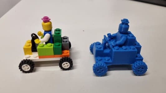
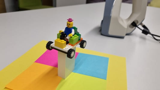
Second attemp I switched to a car model. I placed it on a little stand so it would be raised up slightly and allow me to scan more of the underhalf. I however still had issues of difficulty aligining the scans as the base was all one colour.
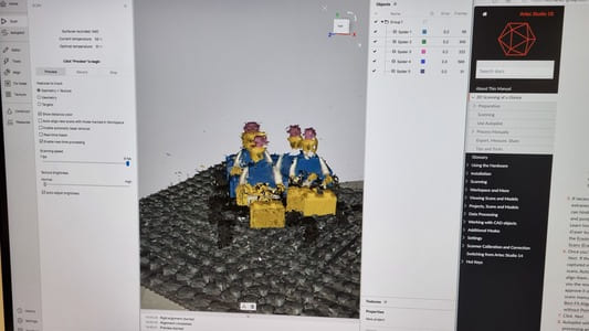
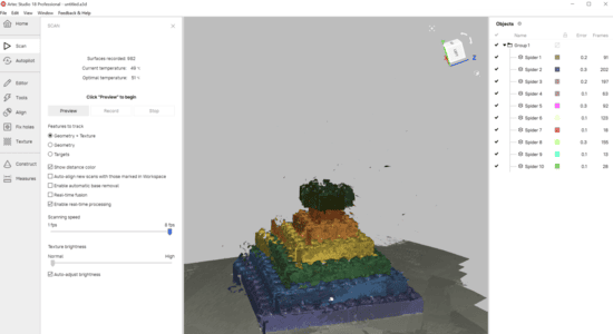
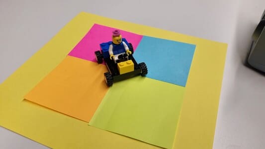
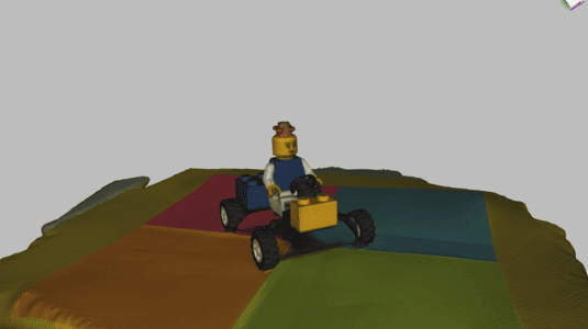
Third attempt I used sticky notes to create a tiled underhalf to help differentuate the sections and hopfully improve the alignment and scanning. This did seem to work much better although there was a issue, the base plate of the car was black and the the processed scan it was excluded leaving a inaccurate base.
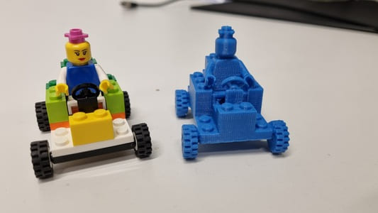
Fourth attempt I remade the car to use a white base. I was much happier with the quality of the scan from this but some of the wheels were missshapen.
Fith and final scan. I placed the car upon a upright stand which allowed me to scan more of the wheels and underside of the model somewhat. I also was very careful to only have 1 full scan. I did this by mostly turning the model on a piece of paper then angling the scanner to scan the different areas. Beforehand I was moving around the model which was difficult to do without losing the tracking.
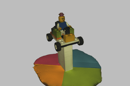
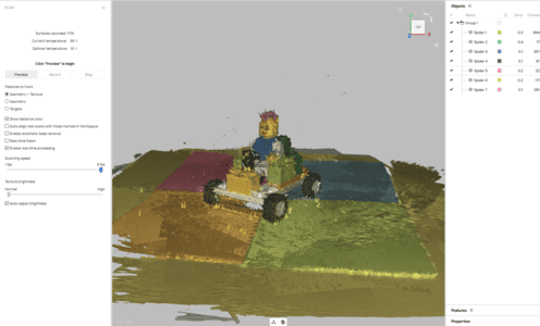
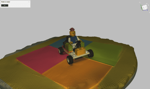
The auto processor goes through all the steps needed to create a complete model from the scans.
I am personally astounded by how well it works.
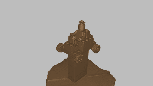
I imported into fusion. Simplified and scaled the mesh. Used plainer slice to remove the bulk of the extra unnceccessary model.I then converted into a solid. Used a sketch to just finish flattening the bottom of the car.
I then sliced and 3D printed the model.