1. Computer Controlled Cutting
This week we looked at laser and vinyl cutters.
Lasers
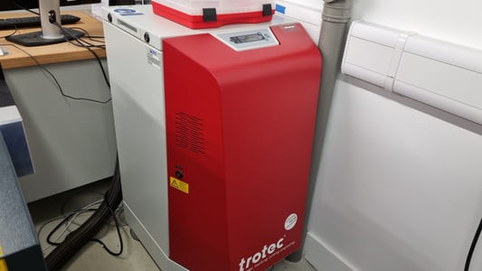
The main types of lasers availble are CO2 and fiber lasers. CO2 laser are more commonly used in makerspaces as they are cheeper to buy and are able to cut a lot of materials, however fiber lasers are cheaper to run and can cut more like reflective metals.
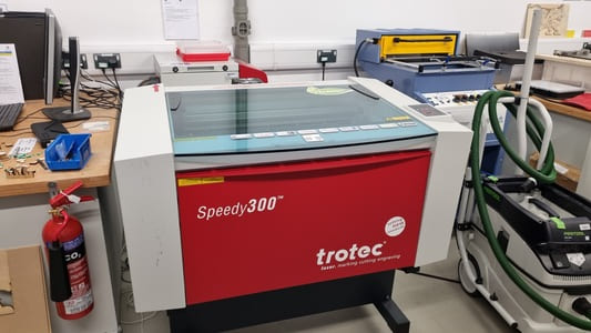
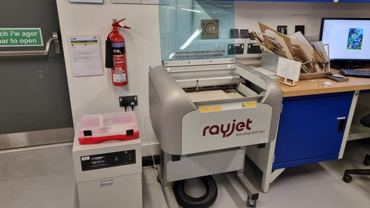
In our fabLab we have 4 CO2 lasers:
For the majority of projects the Rayjet and Speedy 300 have large enough bed sizes so they are more commonly used.
Laser Safety
The main hazzards from a laser cutter are:
Most of these hazzards are addressed by the polycarbonate lid which blocks the lasers light in the result of reflected beam. All the lasers in our lab have extraction systems in place to draw away any fumes as a result of the job. The laser lids tend to have a double-interlock which locks the lid closed during a job.
Here are the Safe Operating Procedures for the lasers.
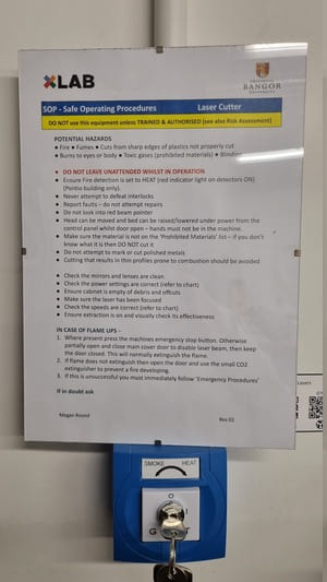
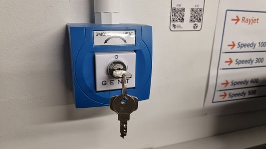
It is also important to change the fire detector from smoke to heat when cuing the laser to avoid accidently setting them off if the lid is opened too early.
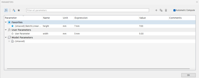
Parameters in Fusion 360
Parameters allows you to bulk chnage values in a design without needing to go through manually. This is useful for when materials change thicknesses, you want to edit the kurf or you want a range of sizes like a taller version.
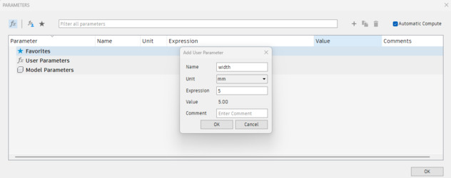
There are two ways to create user parameters. The first is under modify > Change parameters. Then the plus icon to add a new parameter.
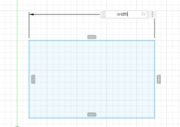
A parameter number has a 'fx' before it.
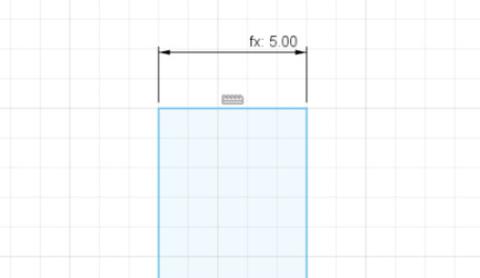
You can then open up a sketch and instead of typing in a number for a dimention you write the name of the parameter and it automatically inputs the current number.
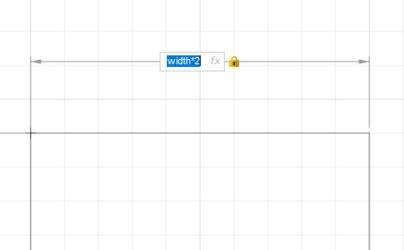
You can then do maths with parameters such as multiply and add/minus.
The other way is to write in the dimentions 'parameter_name=number' it defaults to mm but you can add units also.
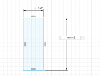
The first time you set it up it looks like a normal dimentional value but for other measurements it has the fx.
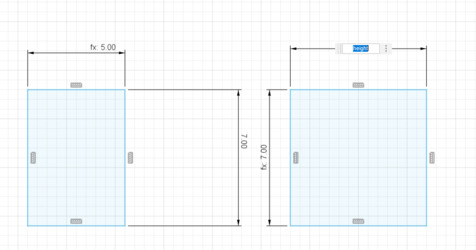
This then appears in the userparameters if you wish to change them later.
2024-02-08
The Laser individual assignment is to create a parametric construction kit.
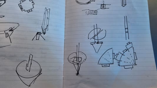
I wished to create a flat pack kit which could be folded to form a spinning top.
I first started sketching options and then started to calculate the maths to figure out the reqired measurements of the flat packed version.
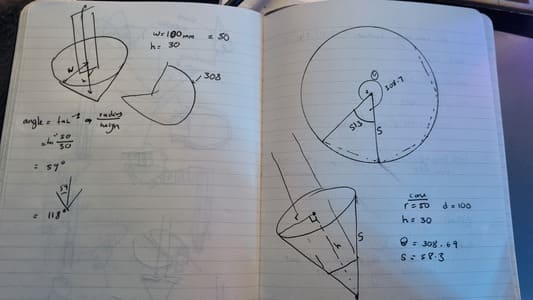
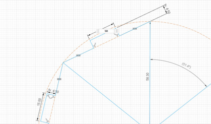
For a cone with a diameter of 100mm and a height of 30mm the slant length is 58.3mm with the angle of the removed section of the circle being 51.3 degrees (360-308.69). I used this online calculator.
However, I plan to make the spinner a heptahedron (base with 6 sides and 6 triangular lateral faces) instead of a normal cone as this would allow for nice bend lines. I chose six sides as 360 divided by 51.3 is roughly 7 giving me a heptagon shape where one 'segment' would be the gap that is used when the heptahedron is folded.
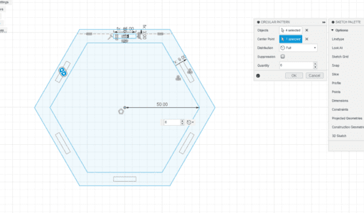
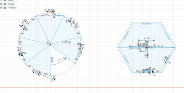
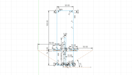
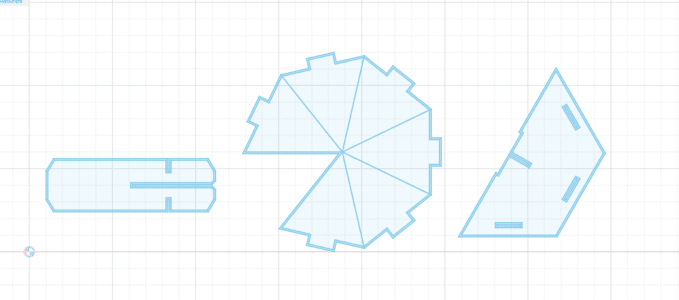
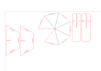
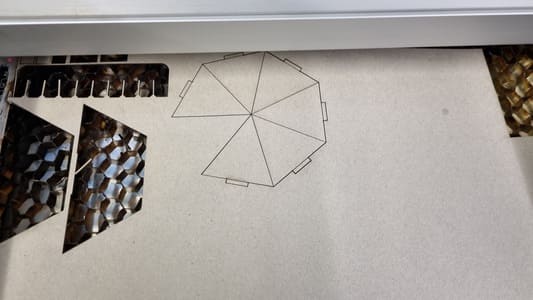
In fusion 360 I started designing the spinner. I used 'Inscribed polygon', changed the number of sides to 7 and the dimaeter to be 116.6mm (58.3*2). I deleted the line on the seventh segment to create the gap. I then created the tabs which will be used to fasten the bottom to the top section of the spinner. Originally i set them as 2*thickness of the material, however I increase this in the version 2.
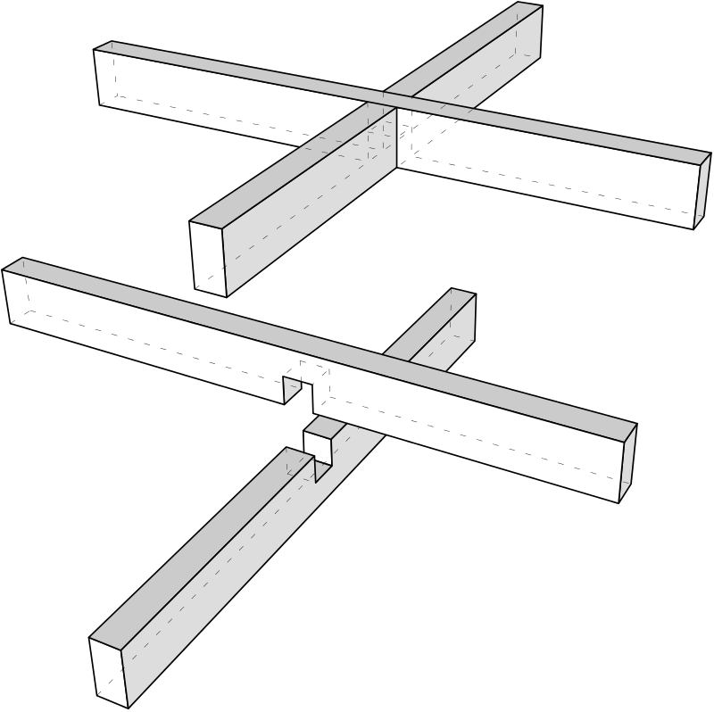
I then created the top face of the spinner. This is a hexagon with the diameter of 100mm, the desired diameter of the finished shape, however this is just a aid to constructing the sketch. The actual outside of the shape is offset from this line as the tabs holes need to be on the initial hexagon. I used the create 'Circular Pattern' to easily duplicate the slots in this face. The width of these slots is a parametric value based on the material thickness and the amount of offset is also bassed off this value. The hexagon is split into two down the center. There are cut outs in the center for the upright of the spinner to pass through and connect to. A halved joint is used here.
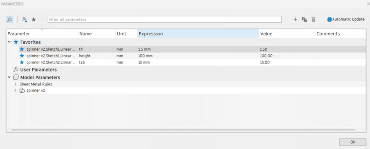
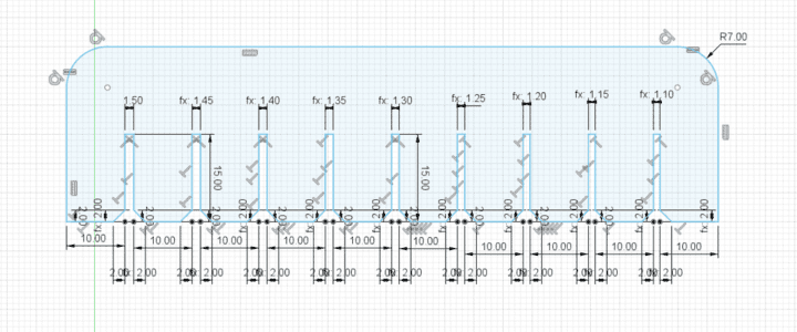
See image below for the parametric parameters used in the sketch.
 Credit Wikipedia
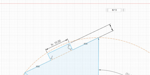
You can see I used the tab parameters on the tabs, useful when there are lots of places which have the same dimentsions.
I have made the height of the tabs parametric based of the thickness of the material so that it would adapt automatically to changes.
The uprights then support the top. They also make use of a halved joint where the thickness of the gap uses the material thickness parameter. I chamfered the edges of the openings. I used construction lines to map out the positions of the sideways slots required in the uprights.
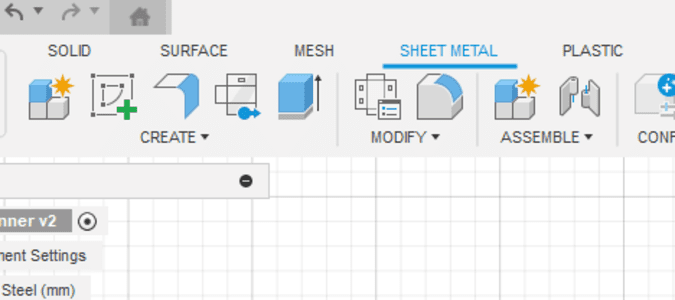
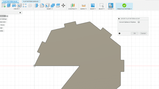
In fusion you can right-click on a sketch and export the DXF file however this also exports the construction lines and I also wish to offset the lines to account for kerf. Therefore I use the sheet metal to export the DXFs.
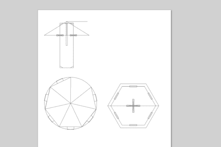
You do this by first extruding the sketch. Creating a flange of a body face. Then 'Create Flat Pattern' and save DXF. This exports a clean DXF which can then be edited. This is useful for when a design uses splines as they tend to not appear when imported into other software as fusion 360 allows for a greater degree of freedom than most.
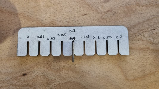
Finally, we import the DXF files back into fusion to add a offset along each of the edges that account for the kerf of the laser. We investigated the kerf of our lasers and found a adjustment of 0.1mm works well.
The comb design had slots which decrease in size this allowed us to test at different kurf offsets. As the thickness of the grayboard was 1.5mm this was 0 kerf then I went down in 0.05 per slot.
The slot which fit the grayboard nicely was 1.3mm, 0.2 difference. However the kurf is half of this as there are two sides so 0.1 kurf.
Click to download fusion file (remember this is for my carboard thickness)
2024-02-13
As I was ill, today was my first oppertunity to use the laser.
I started by doing some work on the group project. You can see this week assignment here.
We used the Speedy 300 for this.
I then found some 1.5mm grayboard which I believed would be a good material for the spinner. The only issue is it tends to tear along bend lines, however it did not cause a big issue. I edited the design files to use a 1.5mm thickness and the kerf value we figured out.
We use CorelDraw to make the final preperations to the design before sending to the print manager. The main changes are:
I cut out the first version on the spinner on the Rayjet 50.
Version 1
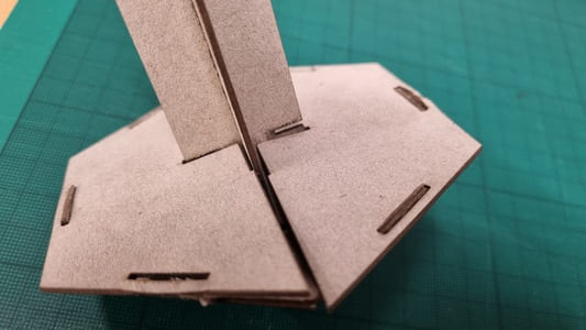
One of the main issues was on the top surface of the spinner. I had made the cross lap joint too long which meant they did not interlock. This meant the upright is wobbly and not supporting the spinner fully.
The second issue i wished to fix was the tabs were too short. It was a bit difficult to get them to stay in the slots which meant the tabs started freying as the slots were too close a fit to slide in nicely.
However, on the whole the spinner spun succesfully and did fit together well enough to survive some use.
Version 2
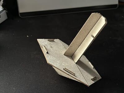
I fixed the issue on the top face and increased the height of the tabs and the size of the slots.
Putting the model together was much easier this time, however the increase in the slot was slightly too much.
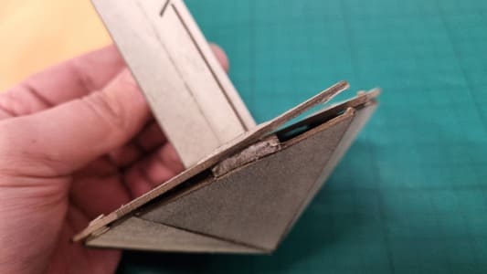
Another issue which was not apparent to begin with in v1 was the difference in angles required on the bottom of the upright as one half followed a seam, the other half follows a face of the base. If it was a true cone there would not be an issue but due to it being a heptahedron the distance to the face is sharter than the distance to the seam. This caused a slight bulge in the top section which pushes the tabs out of the slots. I added a bit of PVA glue to make the joints stronger.
Vinyl Cutters
Vinyl cutters are very usful for making things like durable signage, templates for sandblasting or screen printing and origami.
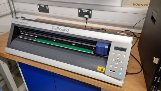
In our fabLab we have 2 vinyl cutters:
The GX-24 cuts rolls of coloured vinyl whilst the SG3-300 pritns and cuts on vinyl materials along with other options such as poster paper and stickers.
Vinyl Cutter Safety
The main hazzards from a vinyl cutter are:
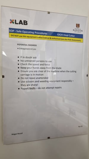
Here are the Safe Operating Procedures for the vinyl cutter.
2024-02-14
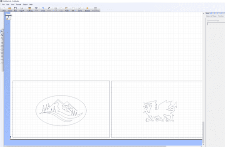
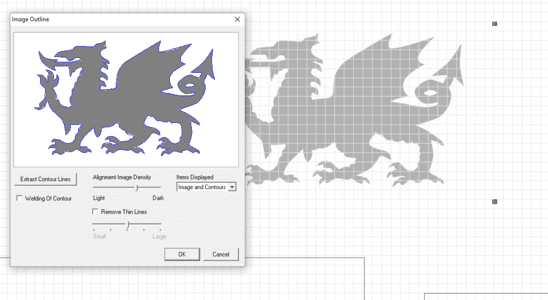
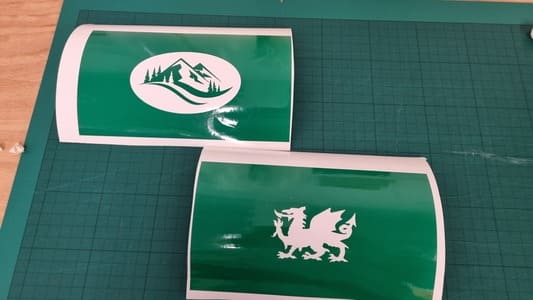
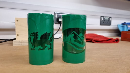
I started making my design for vinyl cutter. I decided I wanted to sandblast a glass. I measured the glass to be 196x115mm with a bit of leeway so it could overlap. I found a picture of the welsh dragon and a nice silluetted image of a mountain.
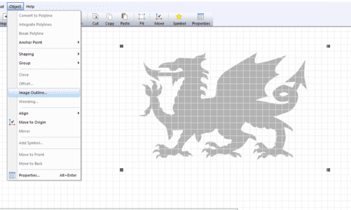
We design the inside Cut Studio. Inorder to use images you import a PNG or JPEG. Object > Img Outline > Extract Contor Lines.
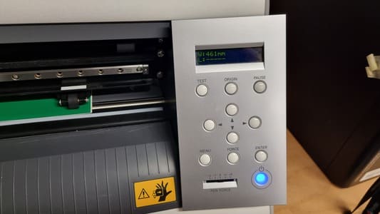
You load the vinyl into the GX20 from the back. Lifting up the clamps and lining up the outside rollers to support the vinyl. Choose thr roll setting and the machine will measure the width of the available material.
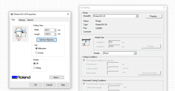
Adjust the size of the design canvas to match the available material by Cut Settings > Property > Get size from machine.
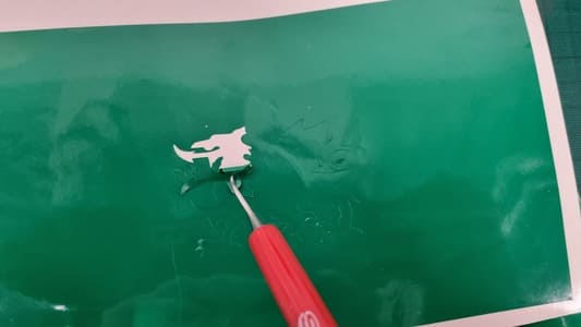
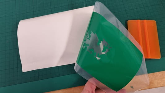
Once cut you need to 'weed' away the waste vinyl that you do not want in the design.
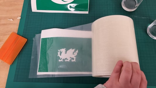
We then use transfer tape to pick up the vinyl from the backing so we can place down on the desired surface. You use a sideways swipe with a spudger to gradually attach the transfer tape to minimise trapped air.
I then wrapped the glasses in the vinyl pieces. One issue I found was the extra leeway I added was not enough and left a gap, however I had plenty of scrap left over to cover this up. I also decided to cover the opening of the glass to avoid any sand getting inside accidently.
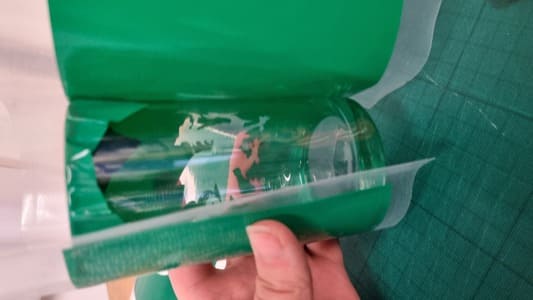
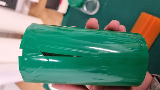
Here is how they turned out. There is some room for improvment but it was sufficiently covered.
Sandblasting
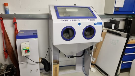
We have a Guyson Blast Cabinaet in our lab.
The main hazzards for a sandblaster are:
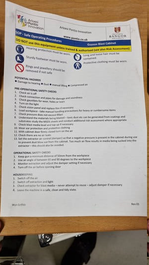
Here are the Safe Operating Procedures for the vinyl cutter.
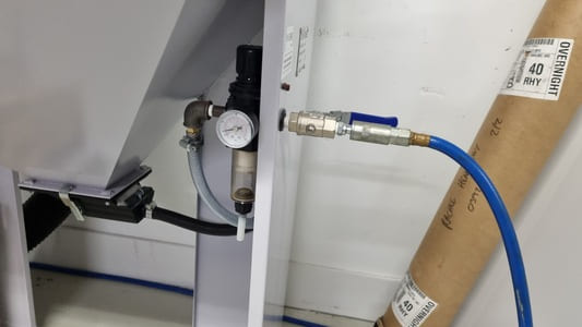
The Sandblaser works by compressing air to around 80PSI and then blasting out the air with sand in order to do the marking.
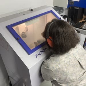
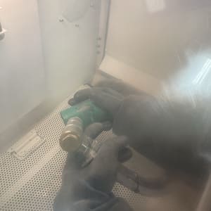
The machine has a extractor to filter the dust and requires ear protection as all the machines are loud. The glass was put inside the chamber then gloves are used to handle the glass and air gun inside the cabinate.
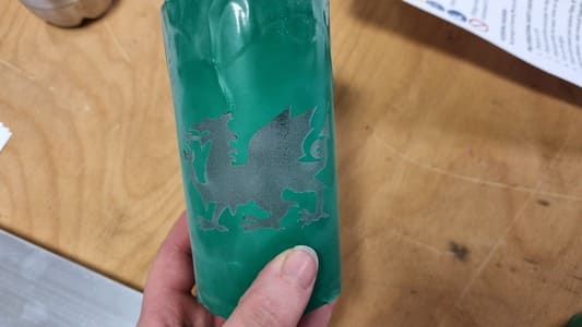
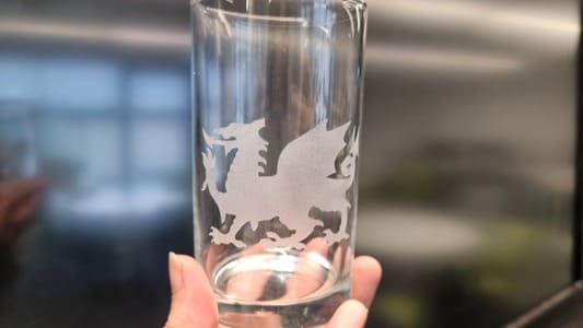
I am very please with the quality of the sandblast. The vinyl protection seemed to seal well and leave nice crisp edges.