Week 6, Electronics design
This week I made a development board.
I didn't want the board to be too complex so i just made it have some very basic features. This was made using a software called KiCad, which I use for all my other boards as well.
I wanted the board to have an integrated button and an integrated LED, and after I came up with a basic design and fiddled around with it to fit correctly this is what I came up with
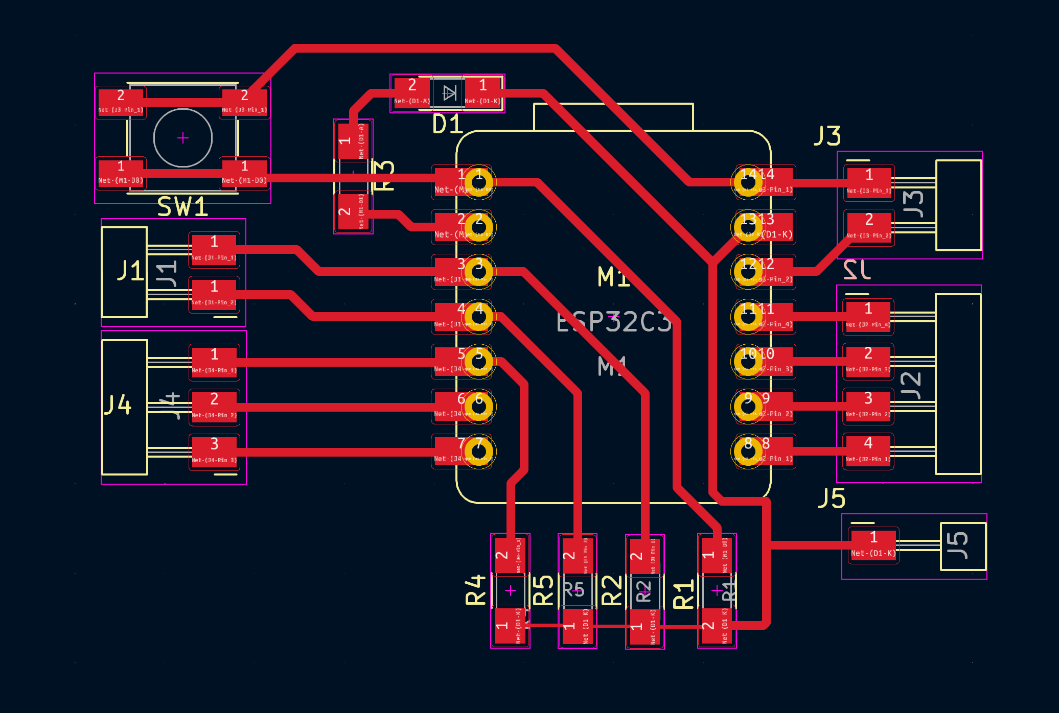
The “brain” of this board is an Xiao ESP32. On the port J3, I have the 2 power outputs, on D0-3 (the top left four terminals on the Xiao) I have random stuff like the button, light and the 2 analog outputs. I have D0 and D2-4 connected to pulldown resistors so that they can become natural input ports (which I don’t think ended up working as I wanted them to.) With that all explained, the next step was to turn this into something that the mill would be able to understand, Gcode. But before that I needed to make this into a file type that the program that I would use to make the Gcode (MODS) would be able to understand. MODS is able to understand png files so that's what I did
I exported the traces of the board from Kicad as a DXF file so that I could open it in adobe illustrator and made this with it
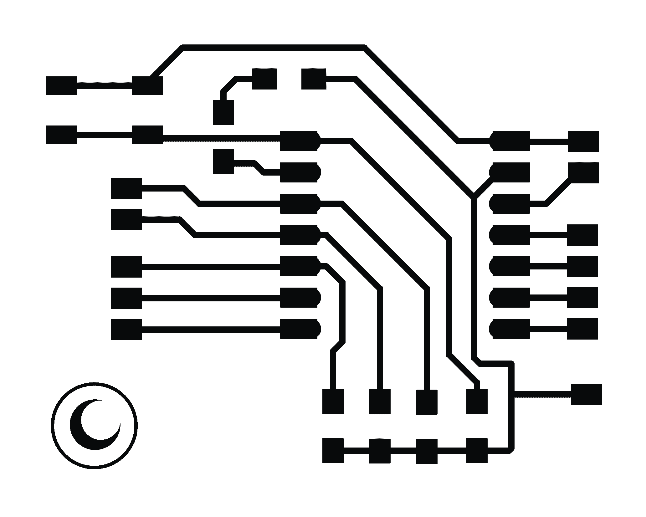
It's a small board that I was able to fit my logo into as well. During this, I noticed that the wire connecting the resistors together was a bit thin so I just used a line tool to manually make it larger.