   Design and produce something with a digital fabrication process
      (incorporating computer-aided design and manufacturing) not covered
      in another assignment, documenting the requirements that your
      assignment meets, and including everything necessary to reproduce
      it.
This week I planned to learn how to weld. It's something I've always wanted to learn, and my college has some good welding facilities in our sculpture studio, the sculpture professor is a friend of mine and offered to help.
The assessment guidelines say that this week's assignment must include digital design, fabrication, or computation as part of the workflow. Our welding and metal cutting tools are entirely manual, but I created a CAD design of the shape I intended to weld in OnShape, and used that to create templates and patterns for manual plasma cutting. This allowed me to visualize the final design, pre-calculate its overall size and weight, estimate the amount of material I would need to order, and think about build process and steps before I got started.
I also think that this wildcard week project serves an important purpose for Fab Academy, by demonstrating that manual skills are still relevant in the digital manufacturing world, and combining the two is a great strategy. Also, my final project will be very digital-design-heavy, and I wanted a chance to go oldschool for a bit.
Another reason for tackling welding for Wildcard Week is that I hope to eventually build a CNC plasma cutting table. Before I do this, I want to get some experience with manual CNC cutting and welding, so I can identify problems with the machine.
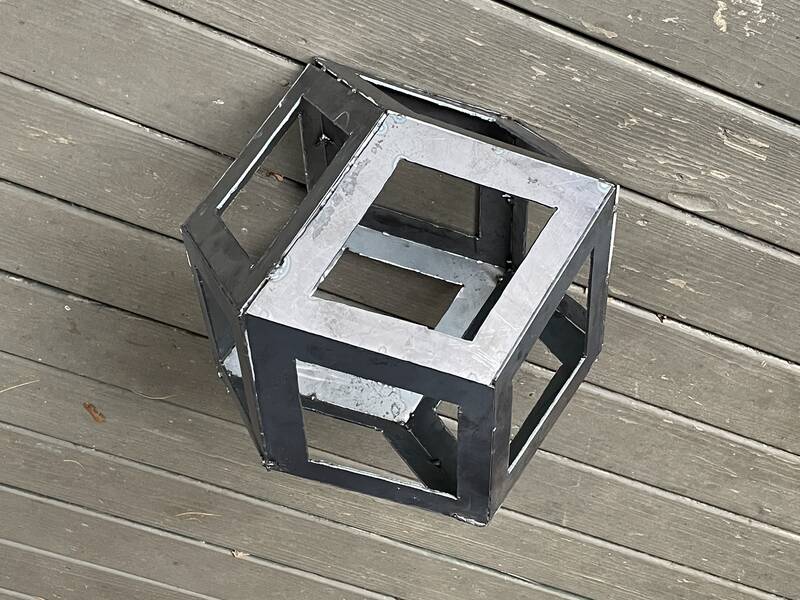
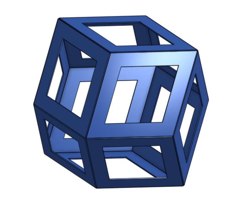
The goal I set was to create an open dodecahedral framework. This is maybe a little challenging for a first welding project, but win or lose I thought I'd learn something.
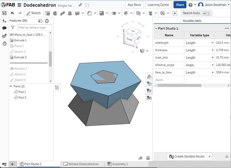
To create a regular dodecahedron design in OnShape, I started by sketching a pentagon, and extruding it with a "draft" to create the dihedral angle of 116.56 degrees between the dodecahedron's faces. I then used OnShape's parametric functions to calculate the distance between opposite faces using Wikipedia info and extruded another drafted pentagon in the opposite direction.
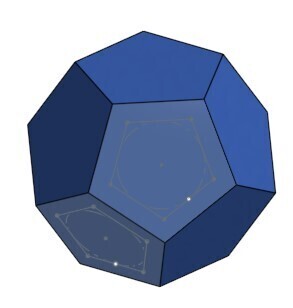
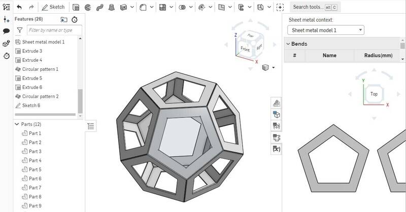
With that done, a simple boolean intersection creates the dodecahedron. The next step is to turn this into a "sheet metal" part. I originally planned to use a press brake to bend some of the shape's edges, but this got too complicated logistically, so I just made separate panels to be welded. I extruded pentagonal holes into each face of the dodecahedron to make an open frame.
Finally, I exported a sketch of one face of the dodecahedraon as a DXF file, to be printed out on paper and brought to the welding shop. I also laid out the parts in Adobe Illustrator to see how to cut them most efficiently, and to figure out how much sheet metal I would need.
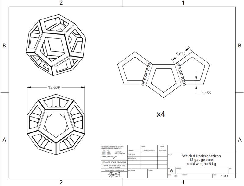
I also created an engineering drawing of the design, just for fun. The image below is the "folded edges" version that I decided against.
Rhombic dodecahedron
In the end I decided I wasn't happy with the regular dodecahedron design. It was a little ordinary looking, and since pentagons don't tile the plane there's a lot of wasted sheet metal and extra cuts. And it has 30 edges, which means a lot of welding work. I decided to go with a simpler but more interesting shape: the rhombic dodecahedron. This has only 24 edges, is easier to cut out, uses sheet metal more efficiently, and looks pretty cool.
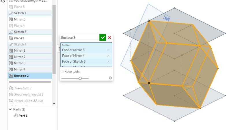
The design process for this was quite different, because this shape isn't quite as regular. I ended up creating sketch planes for three different faces, drawing rhomboids on each of them, then mirroring. I then used the "Enclose" command to turn this collection of sketch faces into a solid object. From there, I converted to sheet metal and cut holes as before.
As before, I exported one face of the design as a DXF and printed it out. I used the "material properties" tools to estimate the weight of the finished sculpture: it should weigh about 12 pounds (5.6 kilos). It will be about 18 inches (450 mm) across. In the end, all this CAD work boils down to just creating a diamond shape. Was the CAD really necessary? Well, the CAD model convinced me to switch to the simpler rhombic dodecahedron rather than the pentagonal one, so there's something to be said for visualizing before making.
I ordered a 4 foot by 8 foot piece of 12-gauge (2.65 mm) hot rolled plain steel sheet from local steelyard Turner Steel. They give free delivery for orders over $150, and by ordering $200 worth of steel I felt like I was taking advantage of them. Great customer service, and they were happy to take such a tiny order. My "tiny" order, by the way, worked out to 140 pounds of metal. I had them cut the sheet in half so it would be easier to carry. As predicted by the CAD modeling, I ended up using a third of it.
I'll be using three major pieces of equipment for this project.
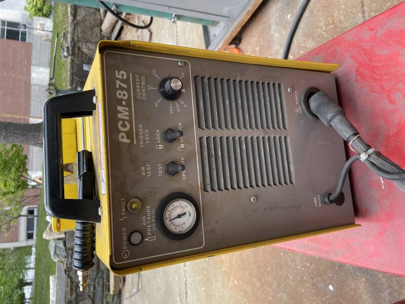
Our plasma cutter
Plasma Cutter
A plasma creates a superheated jet of plasma that connects an electrical circuit between the nozzle and the workpiece. It cuts through even thick steel plates like a hot knife through butter: it is scary how easy it is to use!
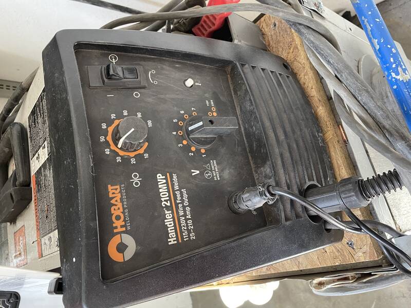
MIG Welder
A MIG (Metal Inert Gas) welder contains a spool of wire, which is pushed out of a nozzle. The wire is both the fill material for the weld, and the electrode that completes the electrical circuit. A jet of inert gas (argon/CO2 mix) surrounds the hot metal to keep it from reacting with oxygen in the atmosphere.
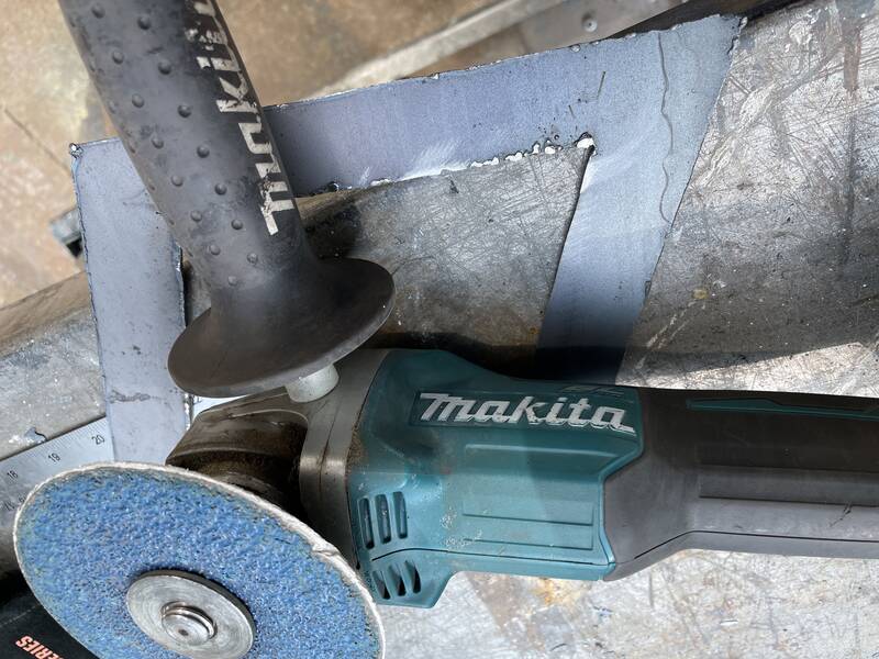
Angle Grinder
An angle grinder is a high-speed grinding tool that is used to clean blobs of molten metal from the plasma cutting and welding process, and (let's face it) to smooth out mediocre welds.
Safety Considerations for Welding and Cutting
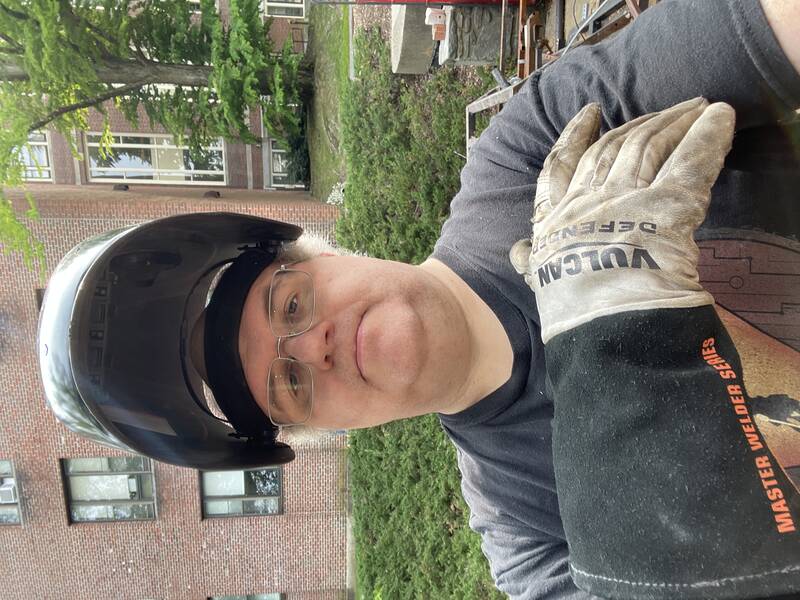
Some of the protective gear used for this project: welder's helmet, leather gloves with .
The plasma cutter throws a shower of sparks, and sometimes blobs of molten metal, out the back of the cut. Always cut downward, and wear long cotton pants and leather shoes. Wearing your pant cuffs over the tongue of your shoes can keep you from getting hot metal in your socks, but even better you can wear leather gaiters.
The plasma jet and welding arcs are too bright to look at safely, and emit UV radiation that can cause sunburn and arc eye (corneal sunburn). Try to wear long-sleeved cotton clothing or a welder's jacket, and always always wear a proper welding helmet. Modern helmets have an auto-darkening feature that lets you see through them normally when the machine is off, and darkens in respnse to a welding or plasma cutting arc.
The metal gets hot, and stays hot for quite a while. Working with welder's gloves is crucial for safety, and also good for productivity since you don't have to wait for things to cool enough to touch.
Welding gives off nasty toxic fumes. If you work indoors, your shop must have a powerful ventilation system specifically designed for welding. I worked outdoors, which is always better. Avoid welding galvanized steel: the zinc coating can cause "metal fume fever", which involves nasty flu-like symptoms.
You may be wearing a helmet to protect yourself from eye damage, but passers-by aren't. Shield your work site from direct view by members of the public. Our shop has some tinted plastic screens for this, but since it was a very quiet day after the semester had ended, I just shielded my worksite with a spare piece of sheet metal rather than setting up the screens.
You might think that working with enough electricity to melt through metal would pose a serious electrocution hazard, but in welding and plasma cutting, the voltages are very low and the currents are very high, and the metal is always a better conductor than you are. The major safety risks are hot metal, toxic fumes, blinding arcs, and ultraviolet radiation. Which is plenty.
Safety Considerations for Grinding
Grinding isn't as unhealthy as welding, but you still need to be careful. Wear a full-face shield to protect your eyes and face from flying sparks, and wear ear muffs or earplugs for hearing protection. Clamp the work to the table so it doesn't fly around, and always cut on the side of the grinding wheel that throws sparks away from you rather than toward you.
Grinding steel always creates a shower of sparks. Pay attention to where the sparks are landing! Lots of really terrible industrial accidents are caused by fires started from grinding. I was halfway through grinding this week when I noticed that the sparks were flying toward a corner of the work area where a gasoline container was hidden! Yikes! Fortunately the container was empty, but that could have been a disaster!
One final safety note: I don't have any pictures here showing me actually welding, because I was working mostly alone (with other people nearby but not Fab students), and I didn't want to think about welding and photography simultaneously. The world is full of people who got hurt trying to get a good picture, and I don't want to be one of them.
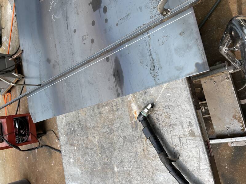
I have learned over the years that spending an hour making jigs, fixtures, and other alignment equipment for a project can save you many hours of work overall. I glued the paper pattern I created in OnShape onto a piece of 3/4" plywood, and then cut it to shape with a table saw to make a template. I used this shape to mark the metal to make the outside cuts for the rhombus faces. First I cut the metal into strips, using the template as a width gauge and a straight piece of angle iron as a cutting guide. Then I used the template to mark the cross-cuts, and used the same angle iron as a cutting guide again. DO NOT TRY TO CUT FREEHAND WITH THE PLASMA CUTTER! Unless you have much steadier hands than I do, you'll just make a mess.
The cutting process is really forgiving, compared to welding. At least for the thin sheets I was using, all you have to do is push the nozzle guide to the metal, pull the trigger, and drag. Speed matters: too fast and you won't cut all the way through, too slow and you'll burn out a wider cut than you want. I found that 1 inch per second worked great for 12-gauge steel, though you can go a bit faster.
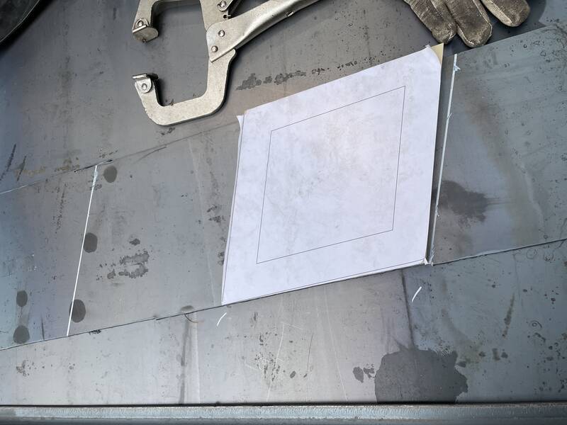
The next step was to cut out the inner diamonds. Once again, I used the template. This time I used a jigsaw to cut a hole in the template that was wider than the hole by the diameter of the plasma cutter's nozzle. That way I can just run the nozzle around the inside of the template and cut a hole exactly the right size!
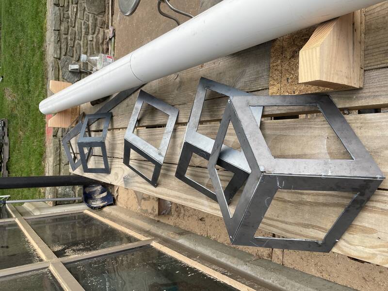
Once all the diamonds were cut out, I ground off the dross with an angle grinder. I made a bunch of extra diamonds, since not all of them came out the exact same size (sloppy work on my part.)
The hole in this template is wider than the intended cut by one plasma-cutter-nozzle diameter, so I can run the cutter along the edge of the template and get the right size hole.
Time for welding! When welding you need to keep about six things in mind simultaneously:
Distance. You want to be as close to the work as possible but you don't want to drag the MIG nozzle through the melted metal.
Angle. Upright is better, but you need to be able to see the melt puddle. You want the tip of the nozzle tipped back by about 30 degrees relative to the direction you want to weld. That is to say, the wire should be advancing toward fresh metal.
Speed. Too fast and your weld bead will coat the surface of the metal without penetrating in. Too slow and you'll burn right through the metal. I found that a bit more than 1/4 inch per second was about right.
Going Straight. This was the hardest part. I had a hell of a time getting my welding helmet to go transparent enough to show me both the weld pool and the surrounding solid metal edges I was trying to weld. Everything was too dark, but I didn't want to make it less dark for safety's sake. I need to get an experienced welder to help me set the visor.
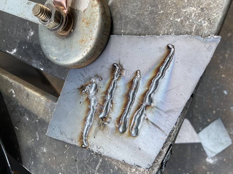
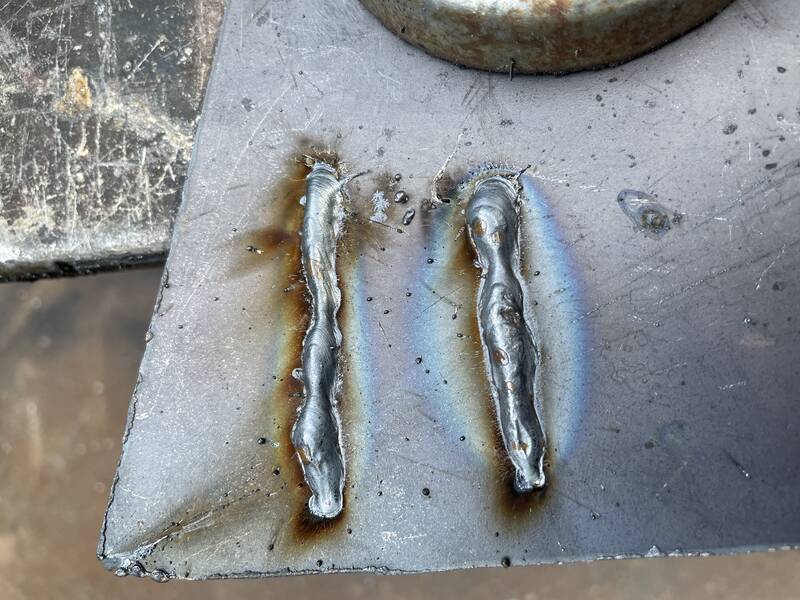
I knew I was going to be terrible at welding, so I did a bunch of practice. First I laid down some beads on a scrap piece of metal.
Terrible welds. Uneven speed, unsteady hands.
Slightly less terrible welds.
Then I tried to weld up the spare rhombus-shaped "donut holes" that I cut out earlier. These are scrap, but they're the same shape as what I'll be trying to weld later. The result was, frankly, horrifying. Good thing this is just practice!
A truly horrifying practice object.
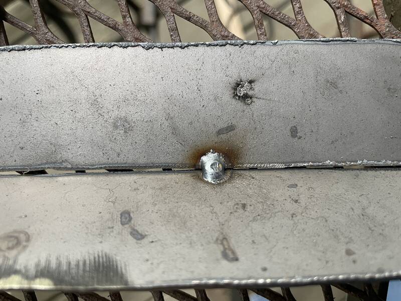
Tack Welding
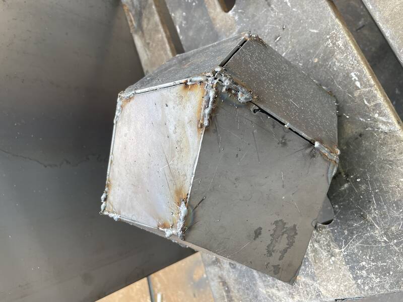
Finally, I set down to weld the actual dodecahedron. I was able to get it tack-welded, but I ran out of time to do finish welding, grinding, and painting. Daylight was fading and people were starting to leave, so I stopped work to avoid any safety problems. I'll finish this up on Wednesday!
A tack weld.
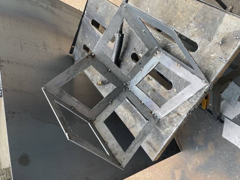
I first tack-welded faces together into sets of three. And I made one extra just in case.
I then joined two triplets together to form half of the dodecahedron.
This is the worst part of the object, this edge just did not come together as planned.
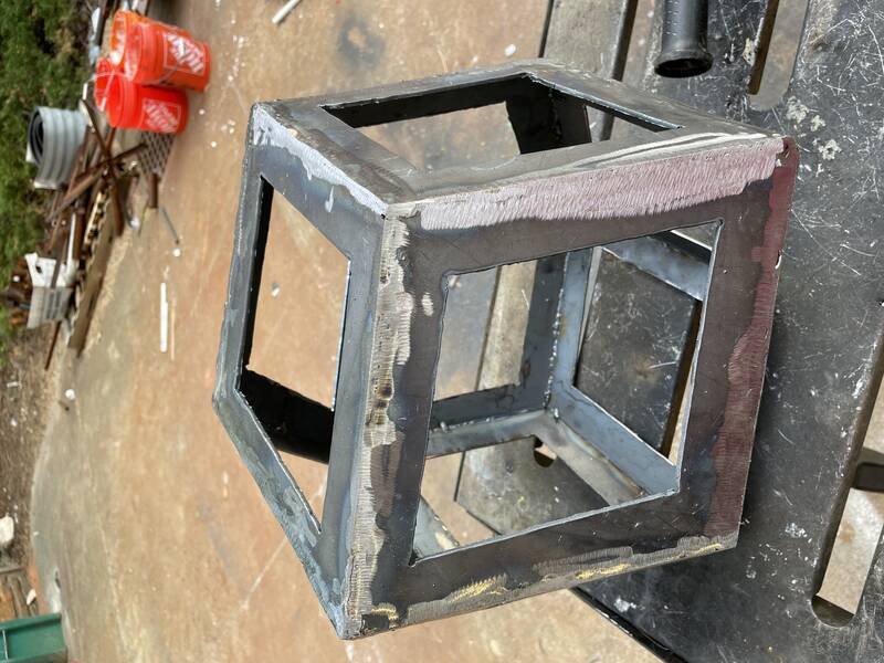
But overall it looks pretty good! At this point, all tack welds are complete: for the first time it's a complete solid object!
Finish Welding
I then worked to finish weld, running a bead down each of the 24 seams on the piece. This was really frustrating, I got a ton of practice at this but I need a ton more.
Finished welding the seams.
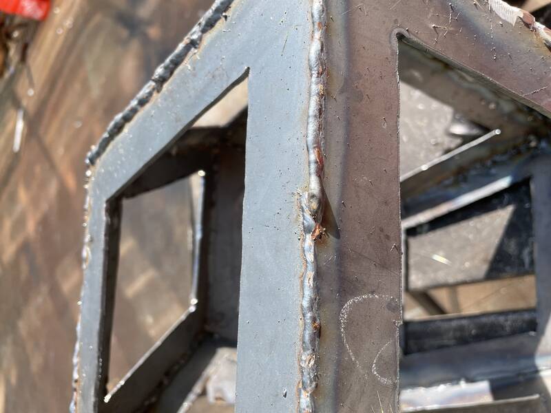
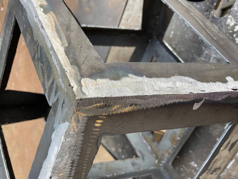
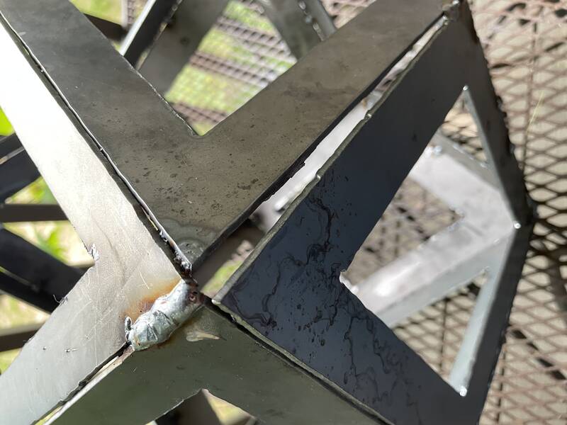
A closeup of a halfway-decent welding joint. There's a void at the center of the photo which would get me fired if I was working on a pipeline.
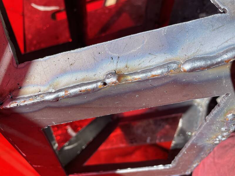
Most of the welds aren't as pretty as the ones above. I managed to bridge the big gap pictured in the previous section by using a higher wire feed rate and welding in short bursts to add material to the edges to close the gap. It's ugly but it will work. I did also leave the gas turned off accidentally for half a weld, after changing out the wire spool. This led to a bubbly weld with lots of voids and a lot of brown deposits.
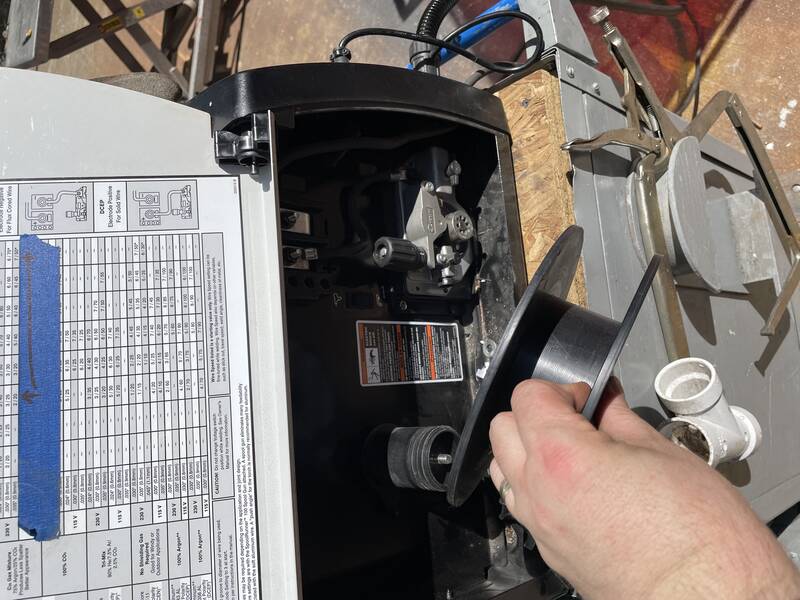
Speaking of settings and changing wire...
Welder settings: speed 35, welding power 4, 0.035" solid core plain steel wire. There's a chart on the inside door of the welder that gives recommendations (visible in the next photo)
Replacing an empty spool of wire. I won't go into the details on how to do this, check the manual.
Grinding
Oh god the grinding. The guys on the Internet say "Grinding and paint make me the welder I ain't", but what they don't tell you is that that it takes 30 seconds of grinding to fix 1 second of bad welding. And I did a whole hour of bad welding. I used a corded angle grinder with a 4.5" solid grinding disk. My goal was to just plane off the weld until it matched the plane of each face. It came out pretty great but took foreeeever.
Safety tip:
Grinding mostly completed.
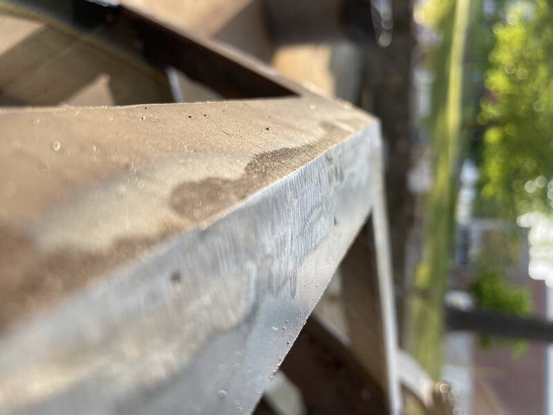
A closeup of some edges after grinding. Nice sharp edges and corners, but you can see that any weld defects become really noticeable.
I was actually surprised at how crisp a line I could get with the grinder once I got some experience with it.


 This is the worst part of the object, this edge just did not come together as planned.