- model (raster, vector, 2D, 3D, render, animate, simulate, ...) a possible final project,
- compress your images and videos,
- and post a description with your design files on your class page
- Find and run through some basic OnShape tutorials
- Create one or two of the challenge shapes I found on StudyCADCAM in OnShape
- Create and render a design of a final project in OnShape
- Use 2-d design tools to sketch a user interface and/or a logo.
- If time permits...
- Find and run through some basic OpenCAD tutorials
- Create one or two of the challenge shapes I found on StudyCADCAM in OpenCAD
- Create and render a design of a final project in OpenCAD
Learning OnShape
OnShape has a good step-by-step tutorial, with videos and step-by-step instructions, and assessment tests to make sure you got key concepts. It even gives certifications you can post to LinkedIn and so on. My only real complaint is that the info is presented in video form, rather than as a text document with still images. I hate listening to people talk, I'd rather read, and a transcript of a video is no substitute. I completed the following self-paced learning modules on OnShape's site: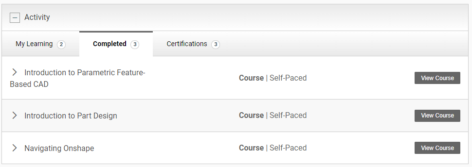
I also started but didn't finish the following:
I have big plans for the sheet metal tool for next week's 2-d cutting class.Challenge Models
I picked out a few interesting shapes from the Web to test my skills.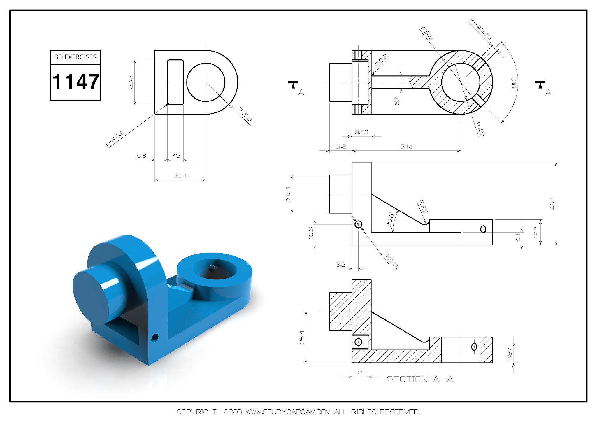
#1147: Flange
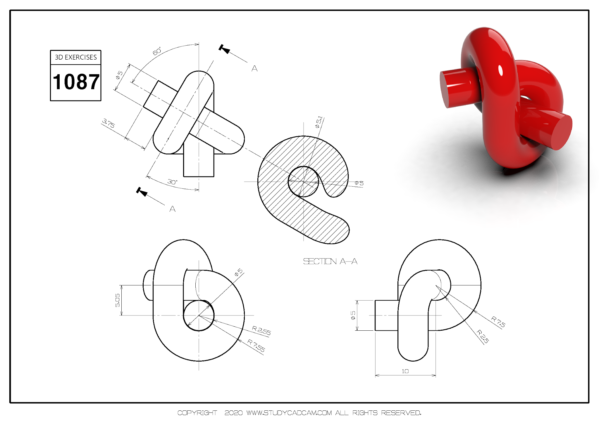
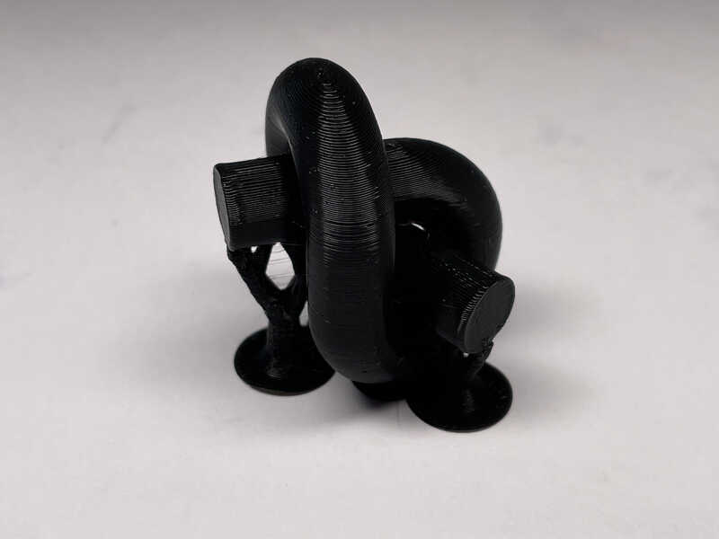
#1087: Knot
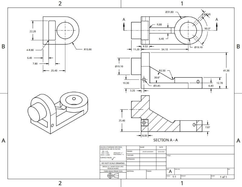
#1147: Flange 2-d drawing
3D design file: studycadcam1147.step
SVG drawing file: studycadcam1147.svg
Comparisons with Autodesk Fusion 360
I'm pretty experienced with Fusion 360, so here are some observations and reactions as I work with OnShape:- Even though it's all in the browser, overall it seems more responsive and faster.
- Sketching is a little cleaner: lines are thicker and more visible, the shapes scale better as you add constraints, and constraint markers are only shown when you want to see them, which is ... maybe better?
- It doesn't have a few Fusion features I got used to (like drawing lines and tangent arcs with a single operation.
- Some balkiness around linear and circular patterns, especially when patterning features.
- It doesn't look like it has any free options for CNC CAM.
- It doesn't look like it has any free options for rendering.
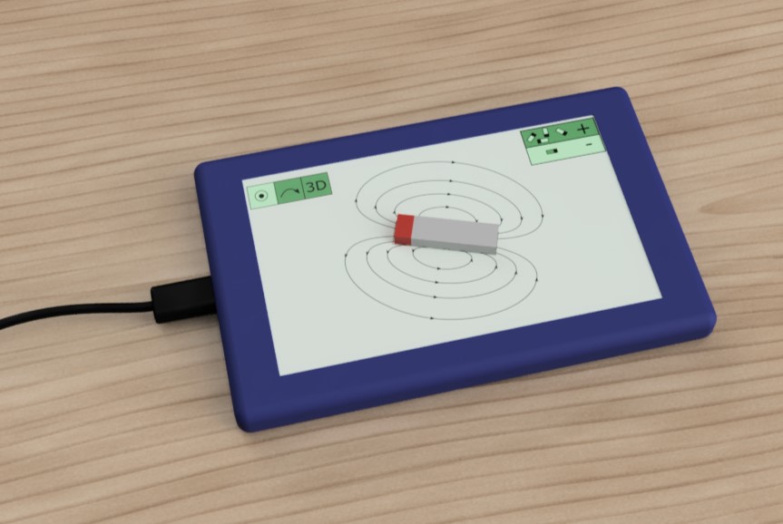
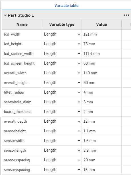
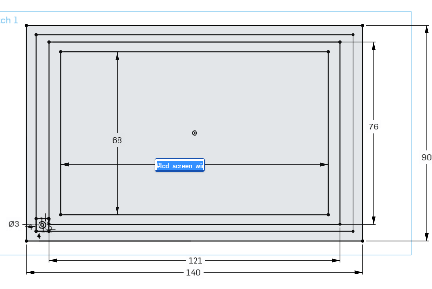
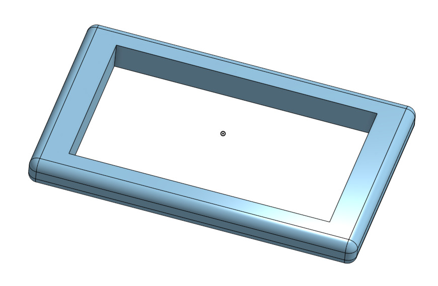
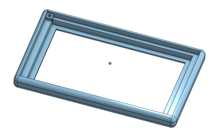
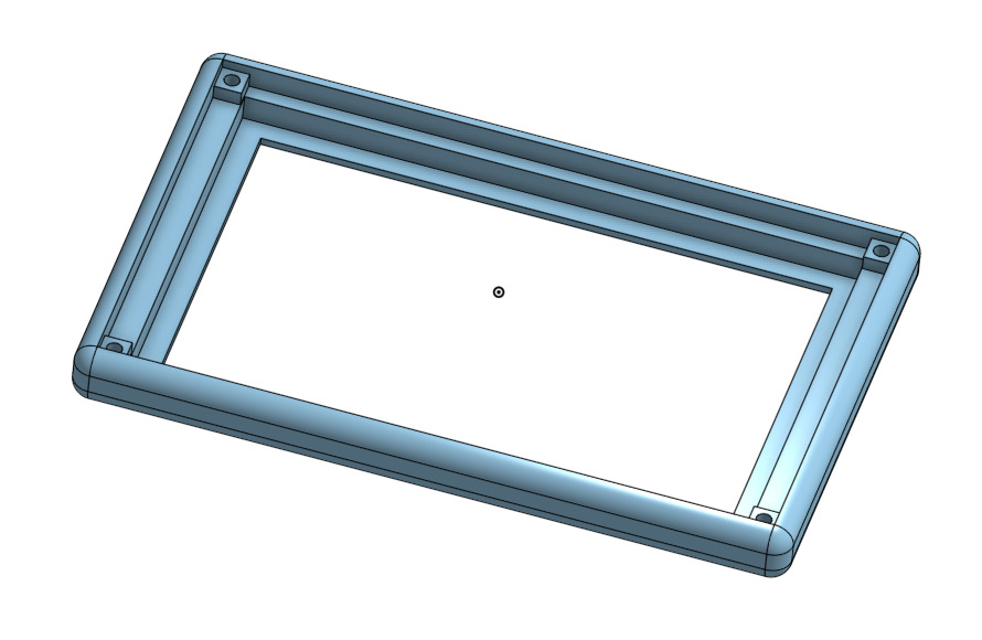
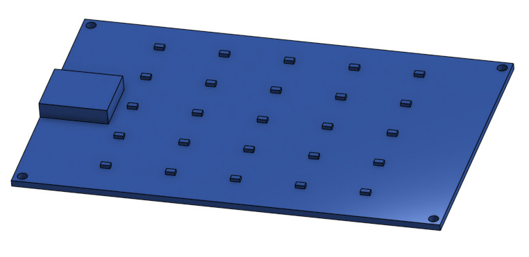
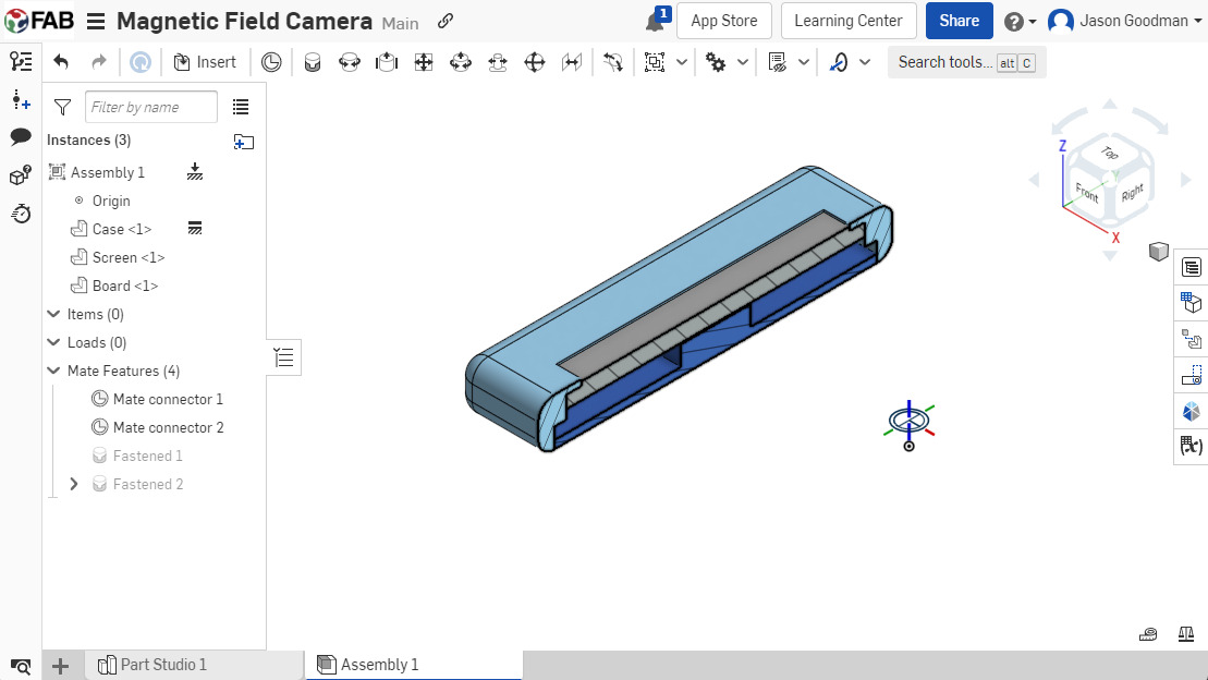
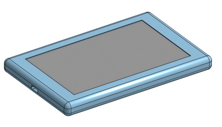
Final Project CAD Design in OnShape
The first step was looking up sizes for key parts that need to go into the thing. Of course I don't know what I'll end up using so this is all placeholders: for now I'm going with a 5-inch TFT display found on Adafruit, the Infineon TLV493D magnetic field sensor, and the Seeed Studio Xiao SAMD21 which I overheard someone mentioning on the Zoom call before class.Actual design proceeded as follows:
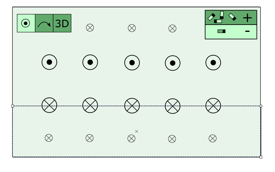
2D Design: User Interface Mockup using Inkscape
I used Inkscape to think about how the user interface will look. I imagine three modes of operation:- "field line mode" will show field lines in the plane of the sensor grid
- "vector arrow mode" will show field vector arrows pointing either in the plane of the sensor grid or perpendicular to it,
- "3D mode" would be the "camera view" showing magnetic sources some distance away.
I drew mockups for the first two modes, but the "camera mode" would involve a bunch of 3-d perspective drawing in 2-d that I didn't have time for, and which would be easier to do in native 3d software, so I skipped it for now.
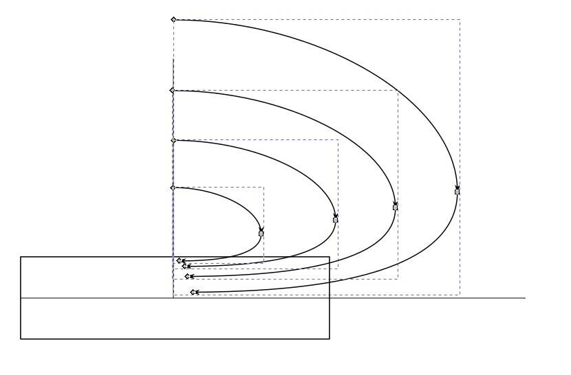
The biggest challenges in this drawing procedure was drawing natural-looking spline curves for the field lines, and making them symmetrical. To achieve symmetry I drew one quarter of one field line, and then duplicated it at different scales and mirrored it horizontally and vertically. It makes me wish I could use sketch constraints in 2-d drawing packages!
Top 5 things I hate about Inkscape:
- Bad "smart alignment" guides
- Tough to tell exactly what you've selected (points, paths, or groups)
- Is there a way to put common colors and styles onto a palette? I can't find it.
- Too much info conveyed through small cryptic icons
- I'm sure I'll think of more as I go on.
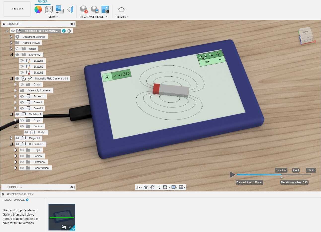
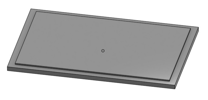
Rendering using Fusion 360
OnShape doesn't seem to have good free rendering tools, so I used Fusion 360 to create the final render. My process:- export a STEP file from my OnShape design
- export PNG files of UI from Inkscape
- import STEP file and Inkscape PNG files into Fusion 360
- Create a permanent magnet, tabletop, and USB cable in Fusion to make the scene more lifelike.
- Apply "appearances" to all objects.
- Apply Inkscape UI image as a "decal" onto the camera's screen.
- Use Fusion's "local rendering" to create a final rendered image of the scene.