2. Computer Aided design
The assignment this week is to make a 2D and 3D digital design of my final project as well as document everything to this page and to my final project page and include design files.
Research
I have completed a few Intro to Fabrication projects using Adobe Illistrate, some examples being an animal sticker made out of rectangles and a D20 die. For this project I will be using the Shape tools to make most of the designs.
2D Design
Using Adobie illistrate I opened the pre-made letter canvus and cut it into four sections using the pen tool with a line width of 2mm. Each of the four sections pertain to a different view, front, back, side, and isometric.
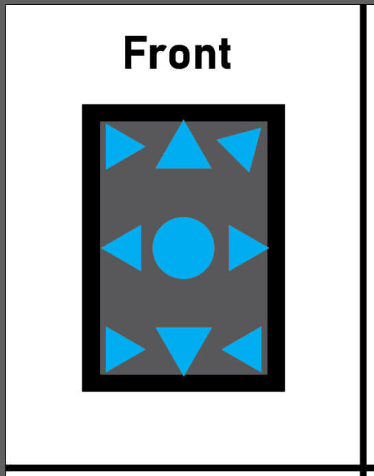
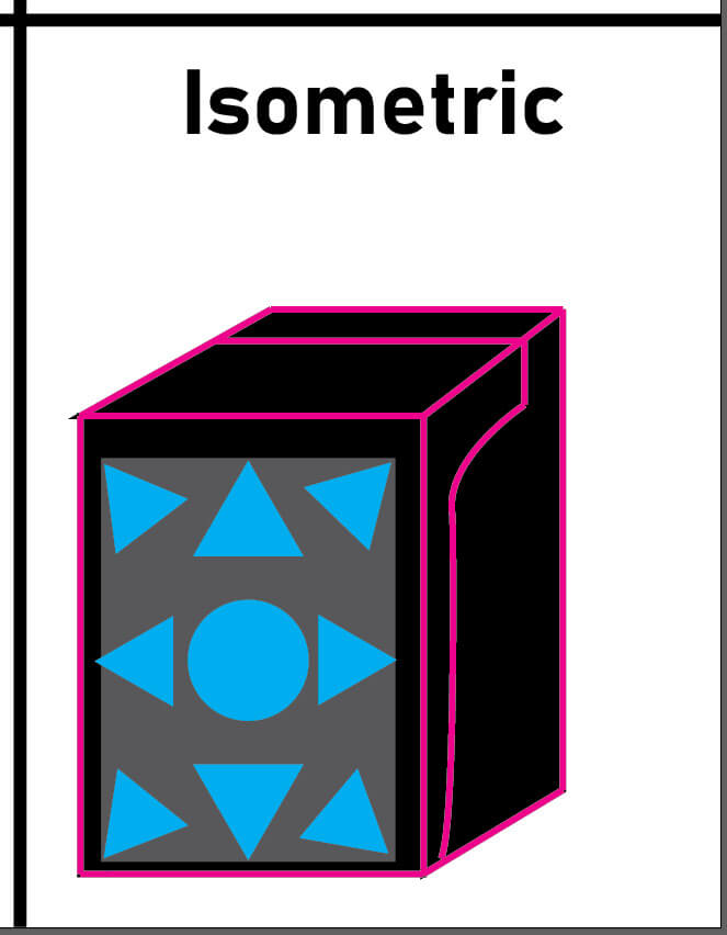
For the first model, the front, I created a black rectangle wirh a grey rectangle on it to represent the total face plate and the panel of plexiglass you would use to see out of it. After this I added a light blue circle and eight triangles to represent my personal logo.
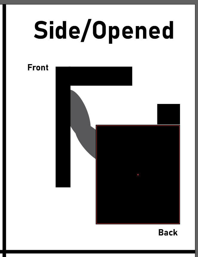
For the second model I used four black rectangles to make the base and faceplate of the helmet. I had to resize the square that juts out from the back (or base) of the helmet a few times as well as make sure the front (or faceplate) would fit on the back by moving it over to it. After those were done I used two grey ovals that I pushed to the background to make up the arm/opening mechenism. lastly I labled the fron and back of the mask to help show the orientation of it.
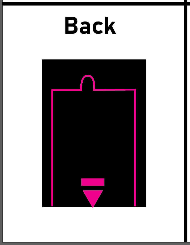
For the third model I copied the black rectangle from the front model and drew an outline for a removable pannel on the back of the helmet. I drew it in pink because other colors like grey, shit I started with, wouldn't be as easy to see as just a thin line. The bump at the top shows where a screw would go to close the pannel and the triangle at the bottom shows where you would slide it towards to open the pannel after unscrewing it. Behind this pannel I plan to put the motherboard, powersource, and most of the wiring in the helmet. The rest of the wiring will be on the inside of the helmet and covered by wire tunnels.
Lastly for the fourth model I used a base black rectangle and drew two aditional black rhombuses to expand the base shape. I then outlined the top, front, and side of the helmet in pink to show each individual face of the isometric design. After I drew the seam between the faceplate and base in pink on the side and top of the helmet. Finally I added the faceplate design by copying the shaped I used in the first model.
Full 2D file
3D Design
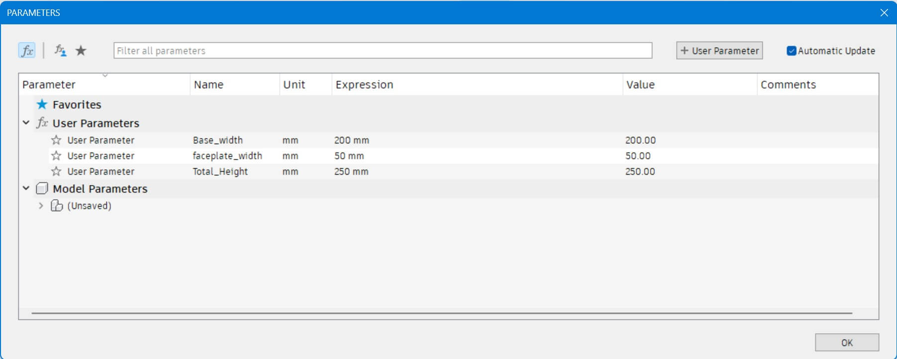
Using Fusion360 I started by making three base parameters, Base Width, Faceplate Width, and Total Height. These parameters are sufficient enough for my 3D Helmet design because they are all using multiples of 50, allowing Base Width to be used for widths and lenghts as well as other parameters being subtracted from eachother to find the desired length. I am using multiples of 50 for right now because the helmet has a very cube-like design and because the full measurment of my head is roughly 10 inches tall and long so when converted to Milimeters, my measurment of choice, it comes out to about 250mm.
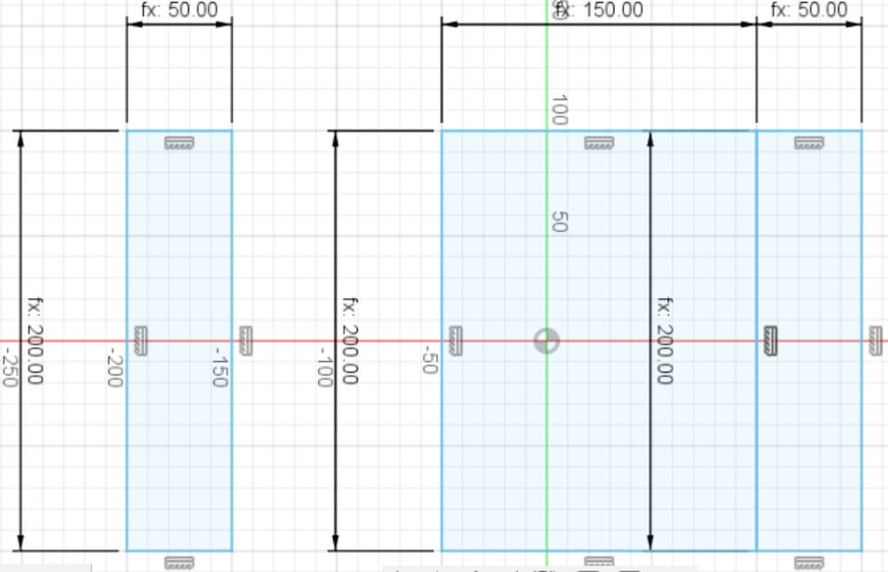
I then made some basic base sketches using those parameters to be extruded.
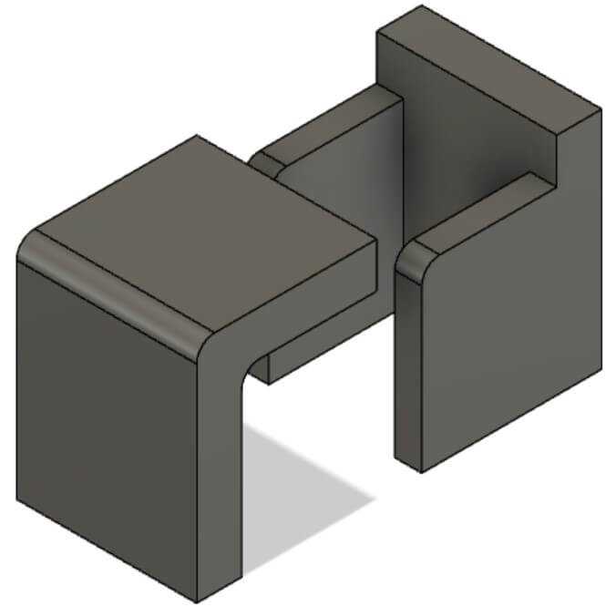
Then I extruded the sketches and made a another sketch on the back of the faceplate to create the top. After this I made the faceplate and base their own seperate components.
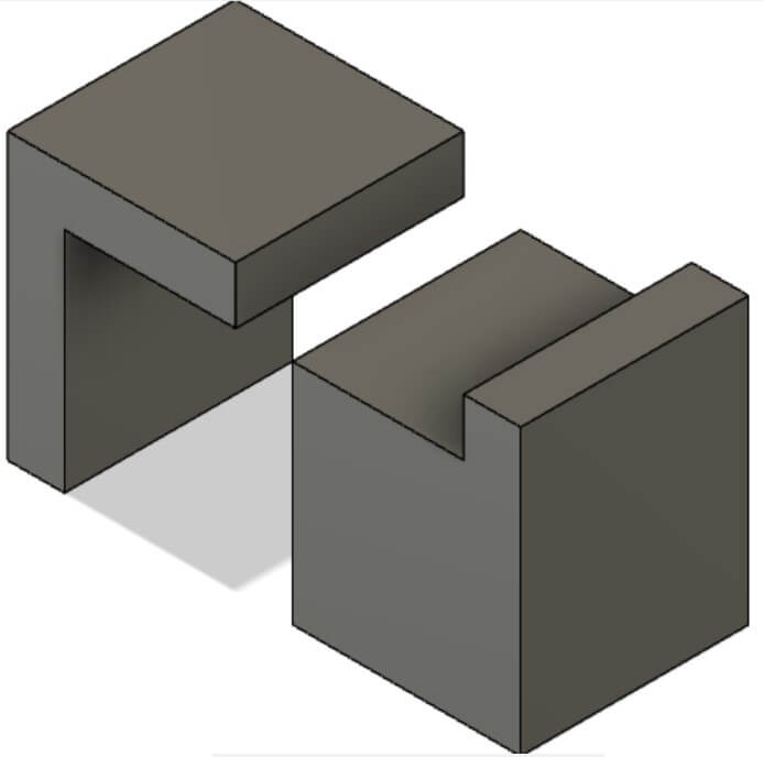
Lastly I filleted/curved the top edge of the faceplate and base to give a smoother design over all. I also cut into the base to make an open space and representation of where my head would go.
Full 3D file