Week 10: Machine Building

This week I worked in a group to make a coo coo clock inspired mechanism. Our group documentation can be found here.


The original idea for the clock was to have a lion head with an articulated jaw that would open every hour to reveal the chicken. My job as we had first divided it was to model the chicken, and create the jaw mechanism on the model that Dara would make. The job of printing the Lion head waited too close to the deadline, in part because it had to be modeled, then sent to me to be worked on my schedule, and then sent back to Dara for finishing touches. By the time it was finished and sent back to me for printing, I found that the print time would be almost too long to finish in time, and then Prusa Slicer had trouble with the complexity of the mesh. Due to this we had a last minute redesign, which I will get to after I describe how I went about the modeling work I had done before it.


Blender chicken

(stl download)

Sphere

To make the chicken model in Blender, I first created a UV sphere with a large number of faces. I would recommend using as many faces as your computer can handle or until you’re sure it will be enough to capture the complexity of your geometry. It is relatively easy to reduce the poly count later on with the decimate modifier, or to multiply it by 4 with a Subdivision surface modifier.

Sculpting

Next I moved to the modeling tab. If there is not one already you can create one at the top of the screen. There are many sculpting tools in Blender, and many can be used well, so I would recommend trying several to find your preference.
I personally like to use the grab tool with high sensitivity to quickly move the shape of the model into what I want.
The draw tools are useful for creating detail and texture, and the grab and pinch tools can be useful for concentrating the vertices of the model into the places where they are most needed.
I also used the masking tool (hotkey m) to mask places where I didn’t want to change at times. I made the edge of the beak by masking the top of the beak, and then pulling the bottom half inward to make a hard edge.
I used the smooth tool often and liberally, as vertices that are too close together or too far apart can stand out in the model, and intersecting faces are bad for 3d printing.
The flatten tool was useful for making the bottom of the model flat, though it didn’t work particularly well, and I ended up just clipping it into the bed in Prusa slicer.

Jaw mechanism

Once I had received the model of the head from Dara, I used the smooth tool and for a bit the grab tool, to fix some of the intersecting faces before moving the model into Fusion 360.
In fusion 360 I imported and scaled the mesh to a size that seemed reasonable at the time, but ended up being a bit too large. Fusion doesn’t have great tools for editing meshes, so the best way to add mechanical structures to a mesh is to create them as steps, and then convert them into meshes and combine them with the mesh join tool. I created volumes to subtract from the mesh, and volumes to add to the mesh, and sorted them into groups to make it easier to visualize how it would all come together. I measured the shape of the lever arm on the servo motor, and made a slot for it to fit into the jaw. I then made a simple hinge system. I planned to join it with the mesh tools in Fusion, but Fusion failed to do so due to the complexity of the geometry. I exported the meshes from fusion and added them back to the blender file.

Blender (again)

Once I had received the model of the head from Dara, I used the smooth tool and for a bit the grab tool, to fix some of the intersecting faces before moving the model into Fusion 360.
I applied the boolean modifier to the Jaw as a way to combine the geometries, though this left a large number of unnecessary vertices. In Edit mode, I deleted the unnecessary vertices and filled in the holes manually by selecting vertices and hitting F to create faces. This took a long time, so if you come to this point yourself, I would recommend finding any shortcuts you can.

Prusa Slicer

I sent the blender file back to Dara so she could make some final changes, and then she sent it back to me so I could print it. To export just a single object from Blender, I found that you can simply delete all the other objects, and then ctrl+z to undo the deletion after you’ve exported the one you want.
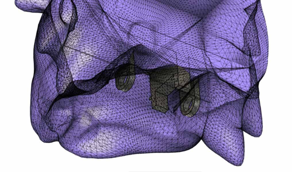
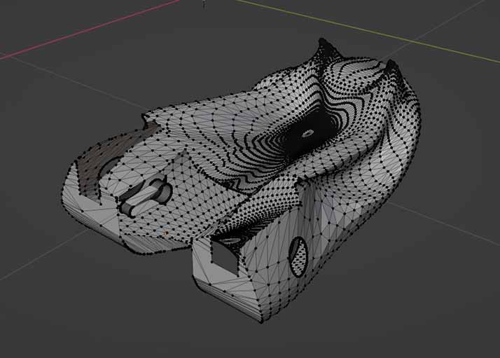
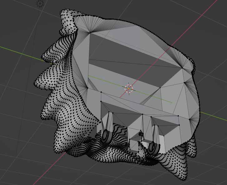
The Jaw printed well, but the Lion Head gave Prusa Slicer some trouble. I messed with the print settings until I had cut the print time by 12 hours down to a day. Prusa seemed to be skipping entire layers in the Gcode, where it would stop and then start again some layers up. I assume this was an issue caused by some of the stray vertices Dara had unknowingly added with her last change, but there was no time at that point for any of us to fix it. I had saved an early Gcode before I had done much with the settings, and I had tried to print that, as I hadn’t noticed it skipping layers in that version. Unfortunately the printer crashed several times near the start of the printing, and skipped one single layer, essentially slicing what little it had managed to print in two.
At this point, around 2 or 3 PM the afternoon before it was due to be presented, we had to change directions and redesign the whole project.

New chicken movement mechanism

We decided to make a wooden house with the chicken popping out of the door every hour. My first task was to make a way to move the chicken in this new form. I created a sketch in fusion 360 with a space for the lever arm to slot in, but with different tolerances than before to account for the kerf of the laser instead of the spread of the extrusion. I moved this into Illustrator, and then emailed it to myself to cut it out with the laser cutter. I created a rectangular hole in the side of the chicken model using the mesh combine tool in Fusion 360. This was so the laser cut arm could be slotted into the new chicken.

Soldering

Once the wiring of the clock was determined, I went about soldering the components together. I stripped a single wire in plany places to act as ground for all of the LEDs, and then, with help from Aziz, I soldered a resistor to each LED. Next I found what I thought to be a couple of shift registers, and soldered wires between them according to a diagram Aziz prepared for me. It turned out that I had taken two entirely different components with the same shape as the shift registers, and so they didn’t work in the end. At this point it was well after midnight, and the soldering of the shift registers had taken a tedious couple hours. I had the idea to take a miniature breadboard, and simply plug the wires into it. After this, it worked, and I left, as it was 5AM.