Week 2: Design
This week I Made a 3d design for the final project that shows the basic shape and movement of the wheel. I also documented the 2d sketch I made last week, which already has most of the detail I need.
2D Design
Photoshop Image of moss ring (download)
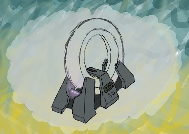
Photoshop Image of back side (download)
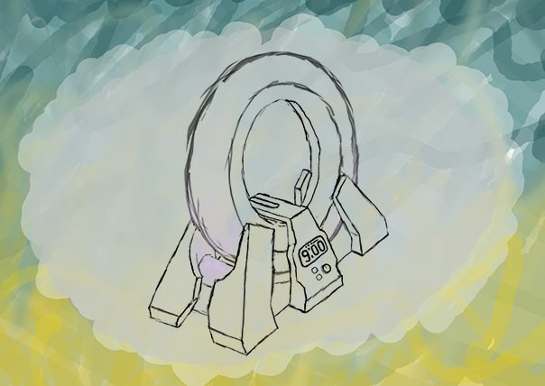
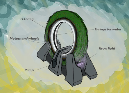
I used Photoshop to create a 2D representation of my design. I was familiar with the basic tools of photoshop before this project. I used a drawing pad to have more precise control.
Background and Sketch
I started by using the brush tool with low opacity to make an abstract background. I then created a new layer and reduced the radius of the brush so I could sketch out my design. I sketched out the basic shape at an angle that showed all of the important elements.
I used the sketch just as a framework to get a sense of the shape.
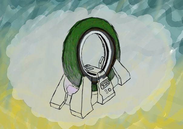
color
With the sketch done I made a new layer, turned up the radius of the brush a little bit, and started coloring the design. The color helps make the design stand out from the background and be more understandable.
With the base colored in, I created annother layer for the color of the moss wheel, and arranged it behind the layer for the color of the base to make it easier to keep them seperate.
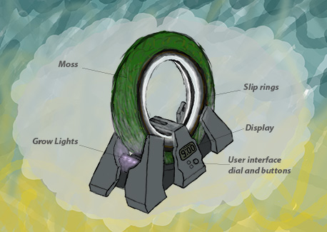
Light glow and labeling
I created the glow of the lights on a seperate layer so that I could change it and erase it independantly of the coloring. I set the opacity and flow at arround 10% and 1% respectively so that I could create a gradient of light. Finally I used the line tool and the text tool to label elements of the design that were not obvious from the image.
Other side
To make the other side, I flipped the canvas using image > image rotation > flip canvas horizontal, then made edits to the sketch and coloring of the base to show the detail on the other side.
3D Design
Fusion design file (download)
I already had some experience with fusion 360, so it seemed like a reasonable platform to build a model of the design. I only modeled the external features of the design, as the internal features will be determined by unknown size and tolerance of parts.
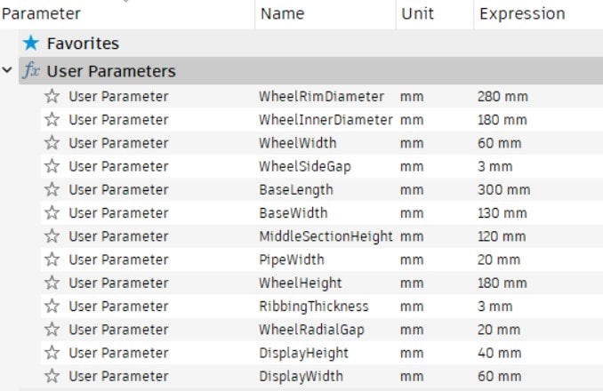
Parameters
To make it easier to make changes later on, I used parameters for some of the measurements in my model. I added a few of the ones I knew I would need at the begining. The rest I added as I went along whenever I was doing something that might effect something else in the design in an obvious way.
Base sketch
To start off I drew a sketch of the top-down shape of the base of the design and extruded it.
To create a sketch there is a button in top bar, or you can go to create > create new sketch.
You then select a plane for the 2d sketch to be placed on, and the top bar will automatically change to the sketch tools tab. In the sketch tools tab you can find tools for drawing a 2d design.
I made the shape of the base with the rectangle tool and the trim tool to get rid of excess lines. To center the design at the origin, I used a couple of lines that are constrained to intersect the midpoints of the sides of the sketch and intersect at the origin.
I turned them into constructions with the button in the sketch info box on the right side of the screen. This made it so they wouldn't divide the sketch into multiple sections for extruding. The height of the extrusion doesn't mater much because I deal with that on the next step.
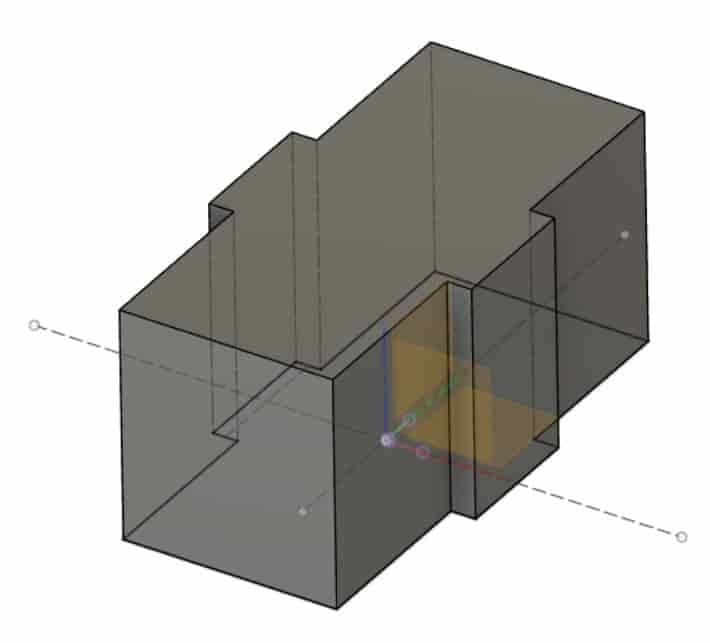
Sketch for Dividing
Next I made a sketch on the y-z plane to divide the base into 3 pillars. This step is mostly just for the aesthetics of the design. I will recombine the base into a single object later on. Once I had a shape I was happy with I selected the negative space that I wanted to remove, and extruded it with the operation set to cut. There is also a rectangle in the sketch that I used to make a surface to draw the next sketch on.
Another Sketch for Dividing
I made this next sketch on a prism extruded from that stray rectangle in the previous sketch. Originally I had made this sketch on the side of the base, but later realised I wanted it to be aproximately normal to the torus. The curved parts of the sketch are from a circle that's mostly trimed away.
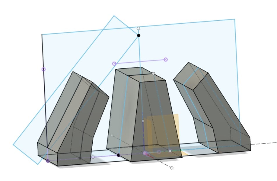
Base taper
To make the taper on the sides I made a sketch on the x-z axis with triangles and extruded them to cut away the corners.
The sketch is mostly constrained by the projections of how the base object was before it was cut. Constraining a sketch in this way can be usefull, because it's easy and fairly robust to changes in your design. If you go back and change what the object was before the sketch, it could make fusion complain about missing geometry, but this is usually an easy and intuitive problem to fix.
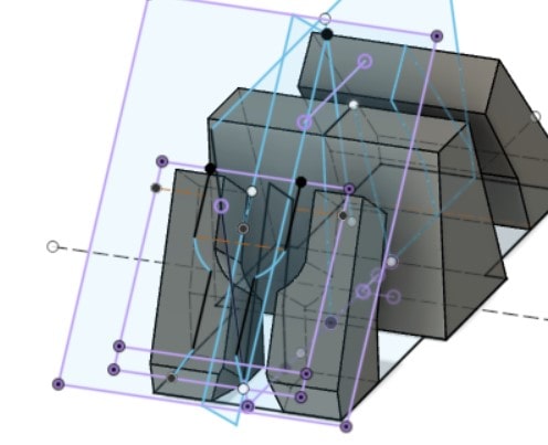
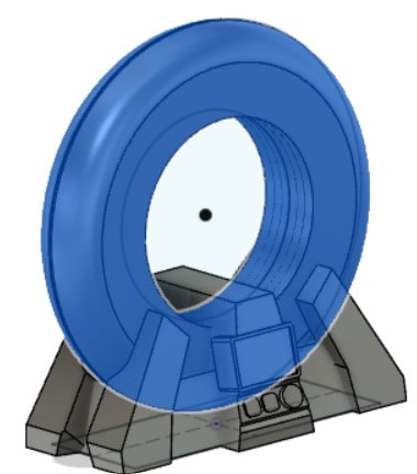
The Wheel
Next I made the sketch for the wheel. This is a sketch with a lot of elements tied to it so I went back to it several times to make changes or additions.
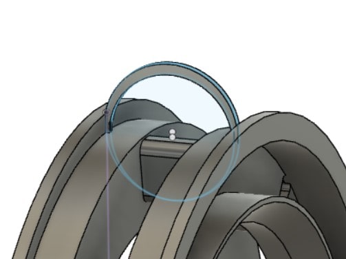
To make the rounded triangles, I started by making a triangle at the top, then used the chamfer tool to round the corners. Next I used the offset tool to make a line arround it. Finally I used the circular pattern tool (create > circular pattern) to copy is 8 times around the circle. This feature is for connecting the two sides of the torus across the water/soil gap such that wires can be fed through.
Symetric extrusions
Extruding all of the features of the Wheel sketch took 7 steps. I used symetric extrusion to make both sides at once.
The gap in the middle was made by extruding the same profile twice, the second time cutting and with a smaller distance.
The angled face was made with the chamfer tool on a circular edge.
The Rib
My current plan for keeping the soil from falling out as it rotates is attatching a mesh to some ribbing under the moss.
To make this sketch I used the x-z plane, and projected the outer corners of the soil channel onto it. Then I used tha same tools as before: circles, lines, symetric extrusion.
Ribbing
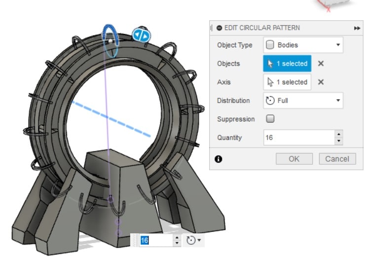
Just like with the sketch earlier I used a circular pattern to copy the ribbing around the wheel.
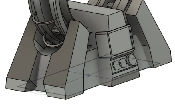
Display and UI plate
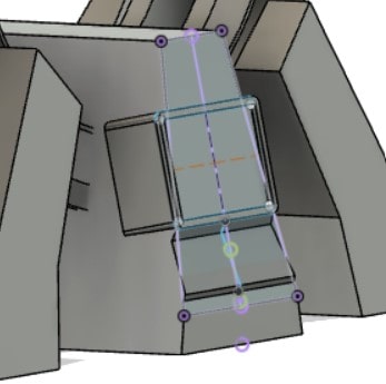
The Display is a sketch on the side of the base, created in a similar way to the wire channels in the wheel sketch. The angled plate for the UI was made using a x-z sketch with the base side projected onto it. It cuts into the base on part of it and adds in other places.
Buttons and Dial
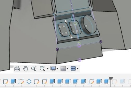
These are just for the visual, and will be removed if I ever use this model to cnc the base. They are made with a sketch and a couple extrusions. To save time one button is a mirror of the other button over a construction line in the sketch.
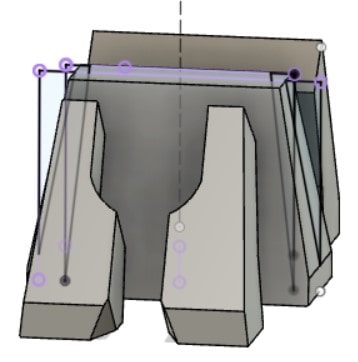
Base reunion
This is the step where I connected the peices of the base back together. The sketch of this is just a rectangle centered on the origin with the measurements equal to the base minus a constant. When I extruded it I gave it a taper angle of -15.
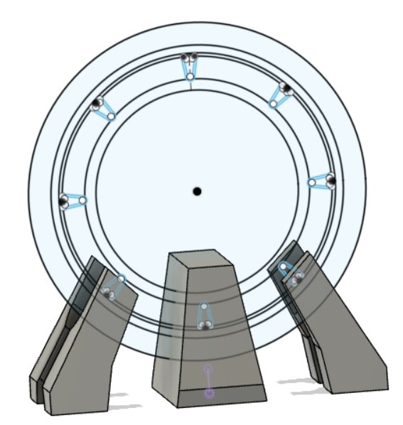
Base exclusion zone
At this point the wheel intersected the base so I created a sketch that goes beyond the dimentions of the wheel itself, extruded it, fileted it, and subtracted it from the base.
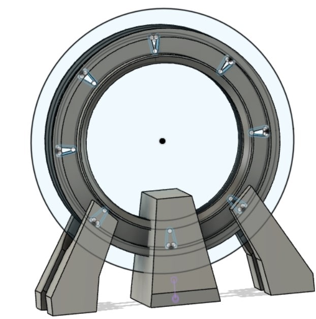
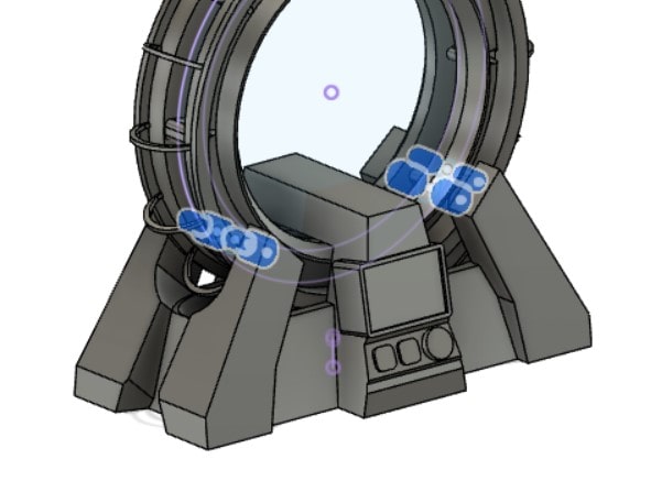
Wheels
The main moss wheel is rotated by 4 drive wheels, each with a seperate motor. It could be powered with only 2 wheels if I made the design more asymetrical, but that depends partly on the specs of the motors I use later on.
For now I have 4 driving wheels that suport the weight of the wheel, and 4 stability wheels that roll on the outer side of the track.
I used a sketch on the z-y plane and 2-sided extrusion to remove the part of the wheel between the sketch and where I wanted the wheel to be.
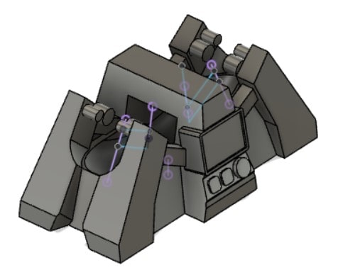
Wire Channels
After considering the issue of wire management and the volume of water in the base, I decided to add more direct connections between the motors and the center pillar of the base where I plan to house the curcuitry later on. Again this is made with a sketch extruded with 2-way extrusions like the wheels. In retrospect this will prove less efficient than using symetric extrusion when I change something later on, but it's not worth changing right now.