This week, I worked with my group to measure the resistance of a thermistor and a photoresisitor. For my individual assignment, I learned the hall effect sensor to measure the strength and direction of the magnetic field, and change the brightness of the LEDs accrodingly.
11. Input Devices
Group Assignment
Coming soon...
Individual Assignment
Idea
My original idea was to animate the location of a magnet using Processing Software, based on the readings from a hall effect sensor, but the sensor I have access to receives the strength of the magnetic field and does not have any means to detect location. So I just ended up measuring the magnitude and direction of the magnetic field and then turn on the red LED when the sensor faces the north pole and the green LED when it faces the south pole, and then, based on the magnitude of the magnetic field, the relative LED adjusts its brightness. However, although I could do this with the Arduino, the code failed with ESP32C3 as the analogRead function did not work for some reason I have not figured out yet. So I ended using the digital input, which turns on/off the relative LED based on the direction of the magnetic field but does not change the brightness of the relative LED as it sends only 0 or 1 inputs.
Hall Effect Sensors(Analogue)
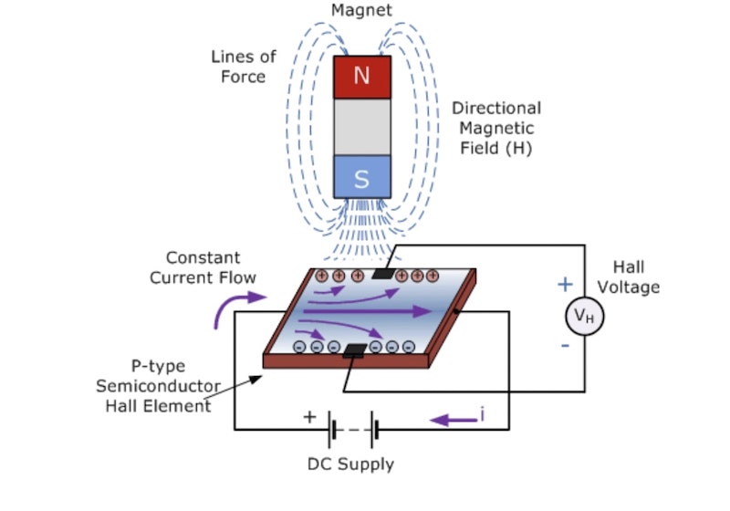
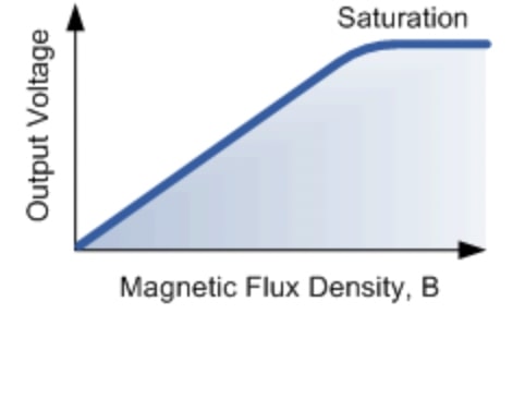
Linear Hall effect sensors consist of a thin piece of rectangular p-type semiconductor material such as gallium arsenide (GaAs), indium antimonide (InSb) or indium arsenide (InAs) passing a continuous current through itself. When the device is placed within a magnetic field, the magnetic flux lines exert a force on the semiconductor material which deflects the charge carriers to either side of the semiconductor slab. The sidewards deflection of the charge carriers results in a potential difference between the two sides of the semiconductor material. The potential difference represnts voltage, indicating that the higher the voltage is, the stronger the magnetic field is. However, there is a saturation limit where the charge carriers are at maximum deflection, meaning that further increase in magnetic field will have no effect on the volatge output; it will just lead to more saturation.
Hall Effect Sensors(digital)
On the other hand, Hall effect switches give an output of 1 when the magnetic field strength(or the potential difference) exceeds a pre-set value. Otherwise, they give out 0. There are two types of Hall effect switches:
- Bipolar: It outputs one when it faces a south pole, but it stays at 1 until it faces a north pole.
- Unipolar: It stays at 0 as long as it is facing a South Pole of a pre-set magnetic strength. Otherwise, it goes back to 1.
KY-024 Linear Magnetic Hall Sensor
| Operating Voltage | 2.7V to 6.5V |
| Sensitivity | 1.0 mV/G min., 1.4 mV/G typ., 1.75 mV/G max. |
| Board Dimensions | 1.5cm x 3.6cm [0.6in x 1.4in] |
Image and Information Source: Datasheet
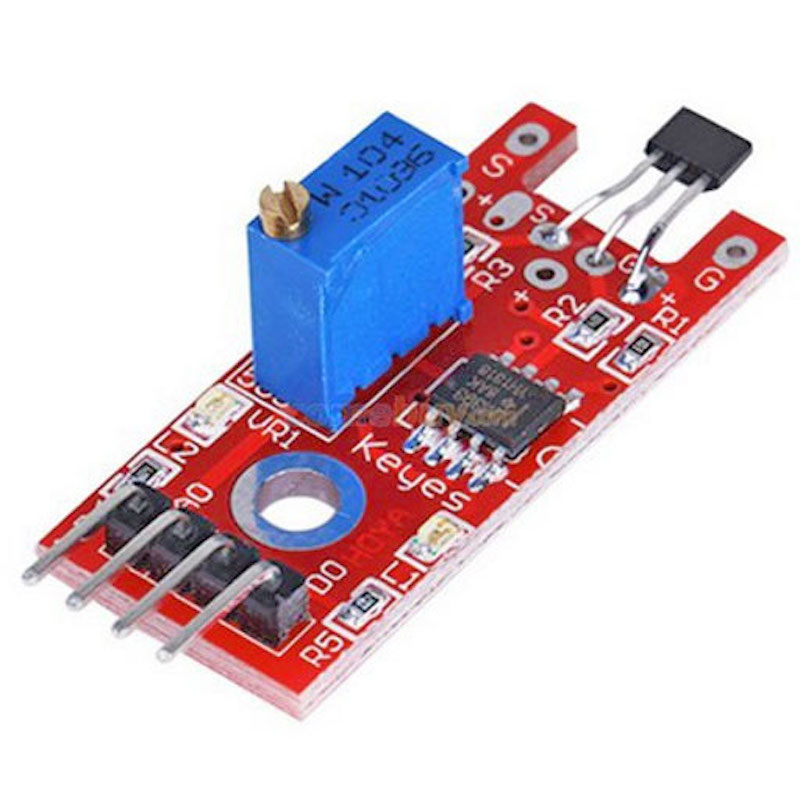
For my project, I used a KY-024 Linear Magnetic Hall Sensor. Having both digital and analogue pins, the KY-024 can act both as a switch and as a linear sensor. The sensor has 3 main components on its circuit board.
- The sensor unit at the front of the module which measures the potential difference and sends an analog signal to the second unit, the amplifier.
- The amplifier amplifies the signal, according to the resistant value of the potentiometer, and sends the signal to the analog output of the module. The senstivity can be adjusted by adjusting the potentionmeter at the top of the amplifier.
- The third component is a comparator which switches the digital out and the LED if the signal falls under a specific value.
Cicuit and Wiring
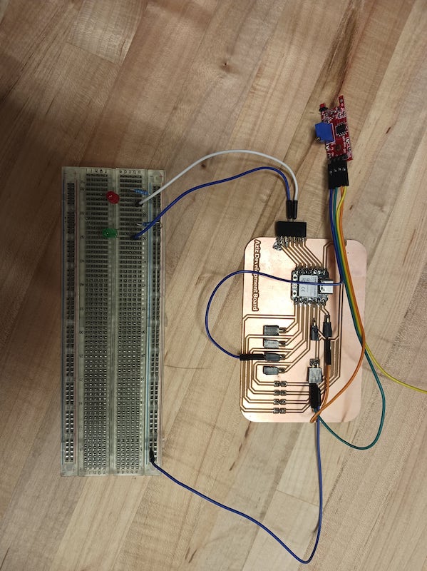
The wiring was pretty simple, so I did not have to draw a diagram using KiCad as I usually do for more complicated circuits. For the Hall effect sensor, I connected -, +, and Digital pins to the GND, 5V, and 9 on my development board I had designed in week 8. I did not need external pull-down resistors as I had them already built-in my board for some of the input pins. Then, I just connected the red and green LEDs to the 5 and 6 pins on the ESP32C3 development board, respectively.
Code

In the Arduino IDE, first, I declared the pin variables. And then, in the setup functions, I set the LED pins as outputs and the sensor pin as input. Finally, in the loop, I first read the state of the sensor using the digitalRead function. If the state is LOW, implying there is south pole magnetic field(or more accurately, positive magnetic field), turn on the red LED. Otherwise, turn on the green.
Video
Here is a video of the final project. As the south pole of the magnet comes close enough to the sensor, the red LED turns on. When there is positive magnetic field, the green turns on.