This week, I used the board I milled in week 8 to change the brightness of an LED based on the readings from an ultrasonic sensor.
9. Output Devices
Individual Assignment
Idea
While this week requires us to use output devices only, I used an input device to as well to make my idea more functional and try a new thing that invloves input and output interaction. My idea was to change the brightness of an LED based on the distance between the ultrasonic sensor and any other object. The farther it is the brighter the LED gets.
Input Device
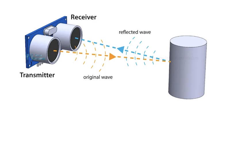
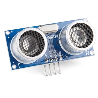
I used an HC-SR04 ultrasonic sensor to gauge the distance an object is away from it. The ultrsonic sensor is composed of two ultrasonic transducers: transmitter and receiver(or trigger and echo). The transmitter emits ultrasonic sound pulses at 40000 Hz, and the receiver recieves these pulses if they get reflected by colliding with an object. Considering the travel time and the speed of sound, you can calculate the distance using the basic formula below, but we need to remember to divide the distance by two as the sound bounces back, and we want the distance only once:
Distance = (Time*Speed)/2
| Operating Voltage | 5V DC |
| Operating Current | 15mA |
| Min Range | 2cm / 1 inch |
| Max Range | 400cm / 13 feet |
| Accuracy | 3mm |
| Measuring Angle | <15° |
| Dimension | 45 x 20 x 15mm |
The I looked up the datasheet of this particular ultrasonic snesor to check whether it was compatible with my board.
Output Device
My original idea was to use a servo and control its angle of rotation based on the distance detected. However, the arduino servo library does not support the ESP32C3 microcontroller. I looked up servo libraries that support the ESP32C3 and found one on GitHub, but it did not work when I tried it. I decided to switch to another output device as I did not have enough time for debugging, and an LED was the fastest option.
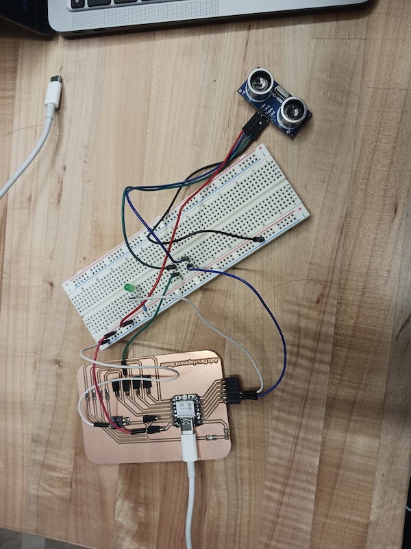
Circuit and Wiring
Using the board I built in week 08, I wired 5V and GND to the board to Vcc and GND on the ultrasonic sensor. To establish the communication between the board and the sensor, I connected the Trig and Echo pins to pins 4 and 9 on the board. Since the echo pin is the input pin, it had to be connected to a pin that has a pull-down resistor on my board. Then I connected the LED to GND and pin 5 on the board. I made sure to use a 330 Ohm resistor to ensure the LED was safe.
Code
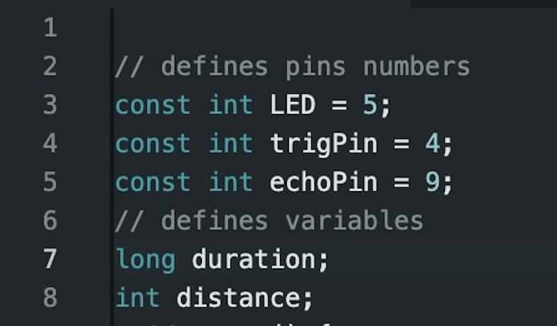
In Arduino IDE, I started a new file and selected the ESP32C3 board along with the appropriate port. First I defined three variables to store the names of the pins and defined distance and duration variables to store the distance and time, respectively.
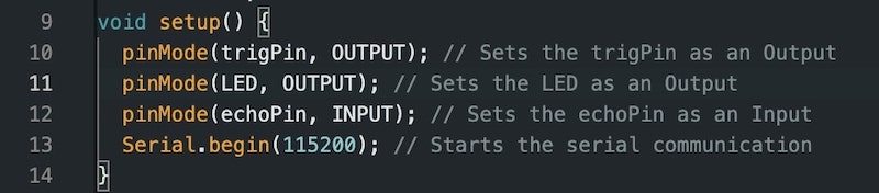
In the setup function, I set the TrigPin and the LED as outputs and the EchoPin as an input using the pinMode() function. I also started serial communication at 115200 baud rate, the default baud rate for the ESP32C3.
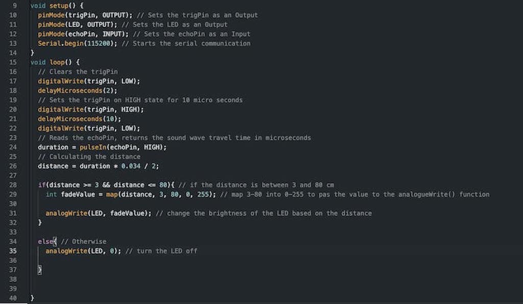
In the loop function, I first started by setting the trig pin to low for 2 microseconds to make sure it is clear before it starts to transmit sound. Then, I set it to high for 10 microseconds, the time it takes it to send an 8 cycle ultrasonic burst. The HC sensor automatically sets the echo pin to high once the 8 cycle ultrasonic burst is sent to listen to the reflected sound, and the echo pin automatically goes back to low state after 38 microseonds if no reflection is received. To get the travel time of the ultrasonic burst, we need to check for how long the echo pin was high, and that is what the PulseIn() function is used for. As we have the duration and speed, we can easily calcuate teh distance using the formula above. Note that in the code, we used the speed of sound in cm/microsecond as we want to calculate the distance in cm. Then, I had an if-else statement that turns the LED on if the distance is between 3 cm and 80 cm and turns it off otherwise. However, to change the brightness of the LED, I used the analogueWrite() function which treats the pins as PWM pins. The analogueWrite() function receives a value from 0(no voltage) to 255(max voltage). Using the map function, I mapped the distance of 3-80 into a value between 0-255 to pass it appropriately into the analogueWrite() function.
Limitations and challenges
- I used a range between 3 and 80 because I noticed that the sensor gets confused when somethig is closer than 3cm to it although the datasheet says the min range is 2cm, and a maximum distance of 80cm was feasible for this particular application.
- Although everything works fine, the serial communication did not work, and the serial monitor does not display anything when connected to the ESP32C3. I tried to change the baud rate, but it still did not work. This was a big downside as I could not read the distance the sensor was reading.