This week, I worked with my group to complete the lab's safety training and test runout, alignment, fixturing, speeds, feeds, materials and toolpaths for our machine. For individual assignment, I deigned a helicopter, milled the parts and assembled them.
6. Computer-Contolled Machining
Design
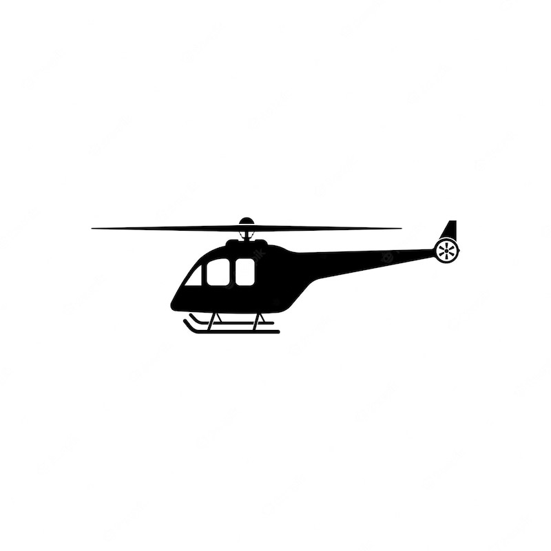
To start, I downloaded 2d drawing of a helicopter and inserted it as acanvas in Fushion 360. Then, I created a sketch and traced the helicopter. I intentionally made the skid and the main rotor thicker just because they looked better to me.
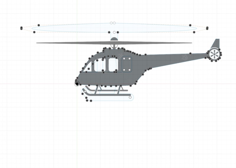
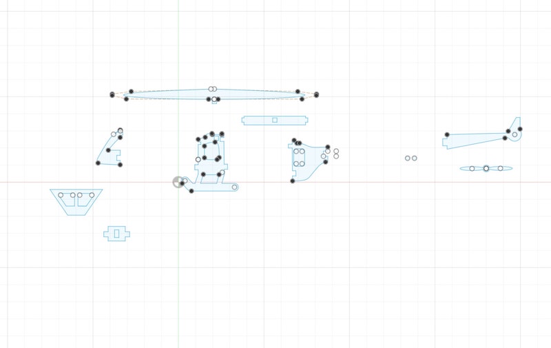
Then, I cut the main body in three pieces and drew joints at the sides so that I can assemble the helicopter without glue: these are the pieces that I need two of each to make a 3d shape. I cut the tail boom and drew a joint for it and same for the main rotor. I also drew the tail rotor which was not part of the canvas with two little circles that I used to fit the the tail rotor in the tail boom. I made a hole in the tail boom for the tail rotor to fit in. I also drew the front of the cockpit to make the final object look more finished. For all of my drawings, I needed only the line, rectangle, circle, slot, and spline tools.
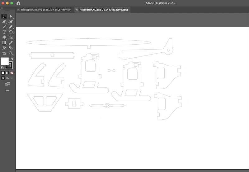
I exportd the sketches as dxf file, opened it in Adobe Illustrator, copied the sketch, and created a new Illustrator file with 4'*2' canvas, the dimensions of the plywood boards and the Axiom CNC bed we have in the lab. I pasted the sketches in the new file to match my machine settings. I also duplicated the tree main parts of the helicopter as I want two of each.
Vcarve Pro
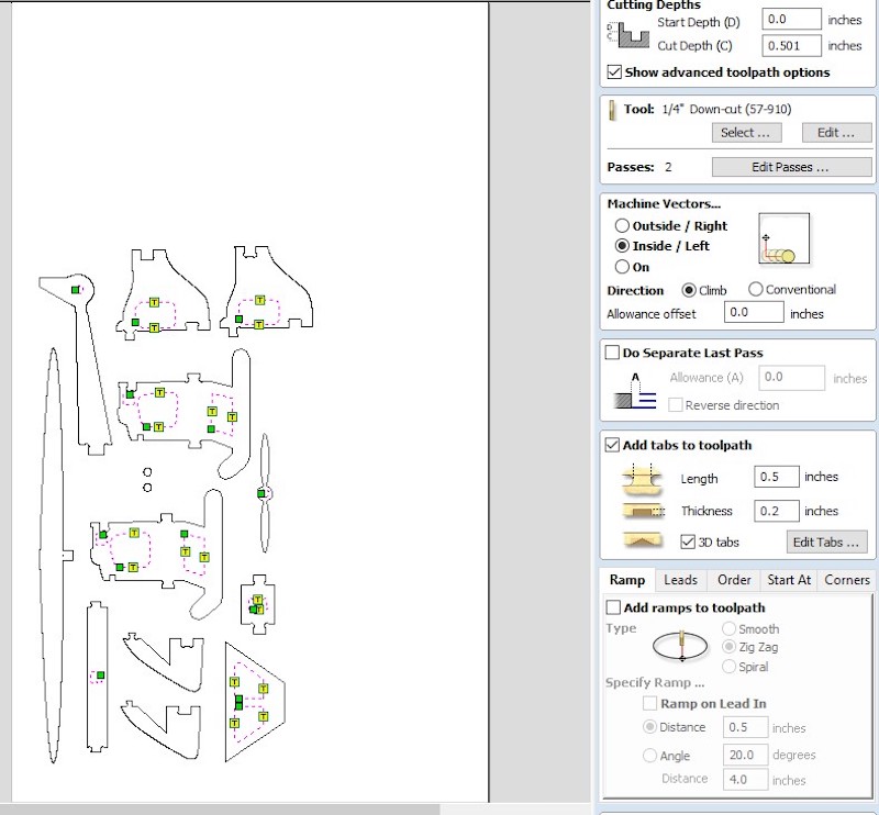
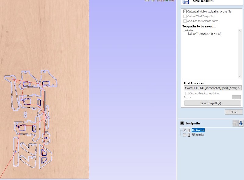
Our Axiom machine uses Vcarve Pro software to the define the sttings of the cut. I exported my Illustrator file as SVG and imported as it as a vector file in VCarve. I split my cut into two: first the interior cuts and second the extrior cuts. THis is to make sure that the cuts that remove the least structural stability occur first. First, I selected the interior cuts and created a toolpath. I selected the 1/4" down cut cutting bit, which set the default speed and feed rate for that bit. I also selected indie cut because I did tno want the machine to remove material from my design itself. I also added tabs to the edges of the interior cuts to make sure the wood pieces do not move during the cutting process. Then, I created another toolpath for the exterior cuts. I chose the same settings, but I selected outside cut this time for the same reason. Additionally, I added dogbones to all inner right angles of joints because the CNC cannot cut perfect right angles. While this is not a problem in general, it is a problem for joints as the pieces would not fit in perfectly. To move on, I exported the two files to a USB disk, making sure they are clearly named.
Cutting
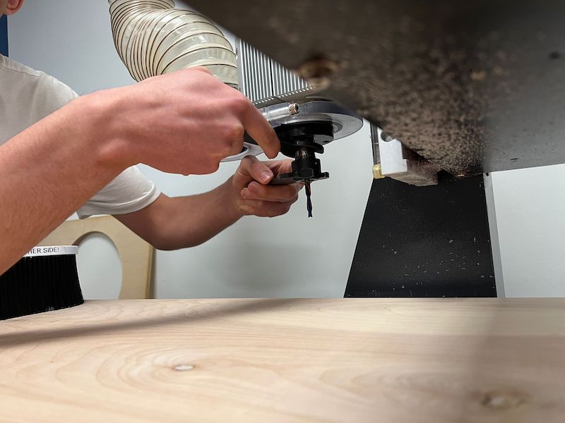
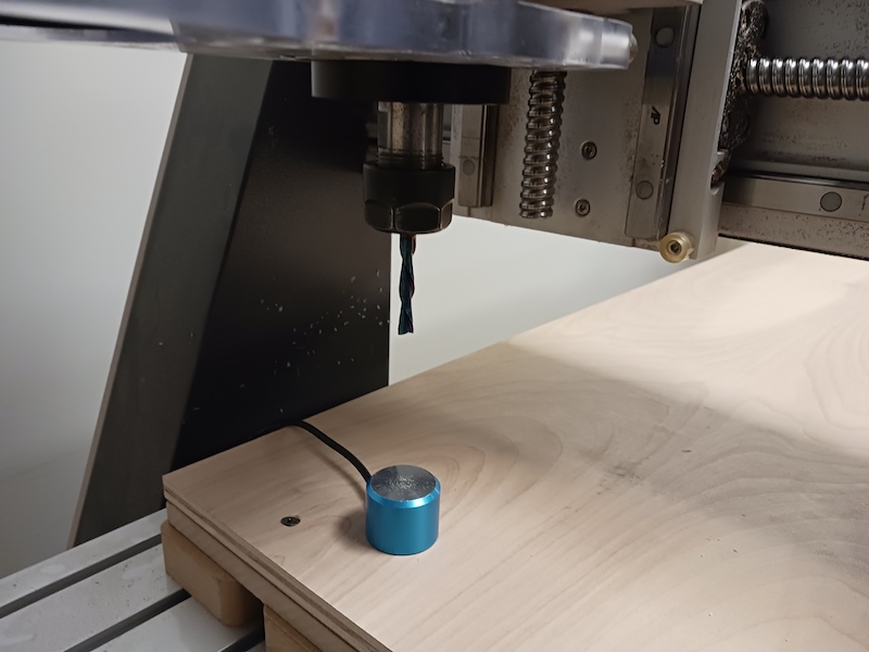
Out lab has Axiom 24*48 CNC. To start the cut, I first took placed a board of plywood on the machine bed, and screwed its four corners using a screw gun to make sure the board is tightly fixed. Then, I changed the bit to the 1/4" bit using two wrenches and made sure it was tightened enough. Changing the bit involves loosening the bolts using the two wrenches till the old bit is free to slide, putting the new bit inside enough so that the collet can grip it well, and then tightening the collet bolts using the wrenches again. While the machine already knows its xy origin, it is our job to z-level it using the metal puck. By placing the plugging the puck cable in the machine, placing it under the cutting bit and hitting toolset of the CNC controller, a full circuit is created letting the bit bounce up. Subtracting the puck height from its total z axis length, the machine now knows where the board is.
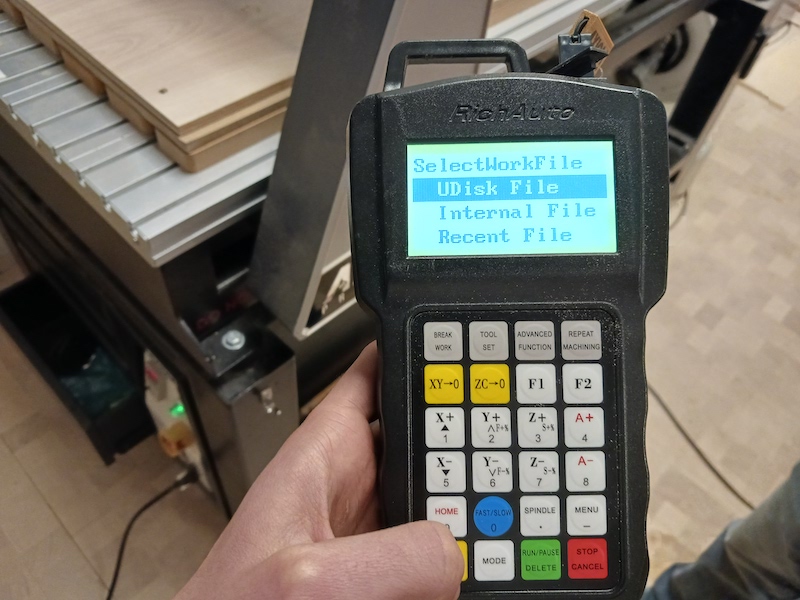
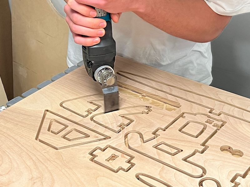
Once the physical setup is done, I put on the ear and eye protection and turned the machine vacuum on to suck any dust while the machine is cutting. I clicked on my interior file using the controller and started the cut. Once the interior part is done. I did the same for the exterior file. Once done, I vacuumed the dust using a vacuum cleaner, cut the tabs using the saw and sanded any irregulars they left.
Assembly
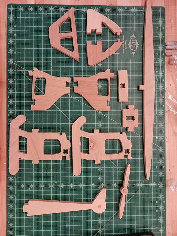
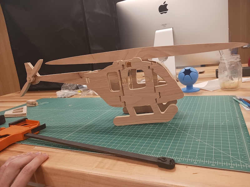
The assembly was very simple. I just fit in the parts according to my design. However, I had to use wood glue for the tail boom as it did tno fit well. For some reason, the machine cut the socket a bit wider than the actual design. I could not figure out why, though. Also, the front of the cockpit did not align because there was a mistake in my measurements. I am planning to fix that later. As you can see, the helicopter does not look quite complete and aesthetic mainly because I did not do it more parts. Cutting it into more parts would have helped making it mor oval and curved. I am planning to improve my design by splitting it into so many parts and adding red acryllic to the windows and cockpit.