This is the second week of FabAcadmey, and the assignment is to create both 2D and 3D designs of my final project and document the process on this page. My final project is a drone.
Computer-Aided Design
2D Design
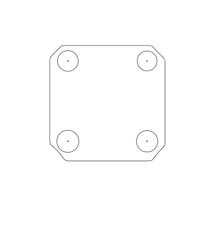
I installed dobe Illustrator on my Mac, and created a new file. First I created a rectangle using the rectangle tool on left bar. Then I erased the corners using the eraser tool to get the center frame of the drone. After that, I drew four circle on the corners using the circle tool. I ended up with this shape.
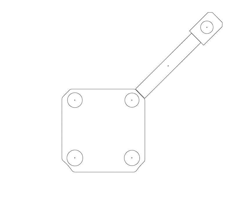
Second, I created a rectangle to represent the arm and attached another rectangle(with a circle inside it) at its end to represent the motor base. I then used the Rotate Tool at the left bar to rotate the shape so that it fits the corner of the drone. So far, I have this:
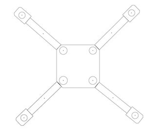
As we need four arms for the drone, I copied the whole arm and pasted it three times. Then I rotated each arm to fit a single corner. Now I have a drone!
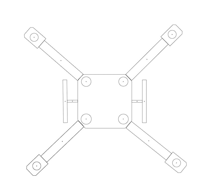
Now I have to design the legs. I created a horizontal rectangle and a vertical rectangle. I placed the center of the vertical rectangle at the top of the horizontal rectangle. And the copied the leg, rotated it 180 degrees, and placed it on the other side to have two legs. The 2D drone frame is complete now.
3D Design
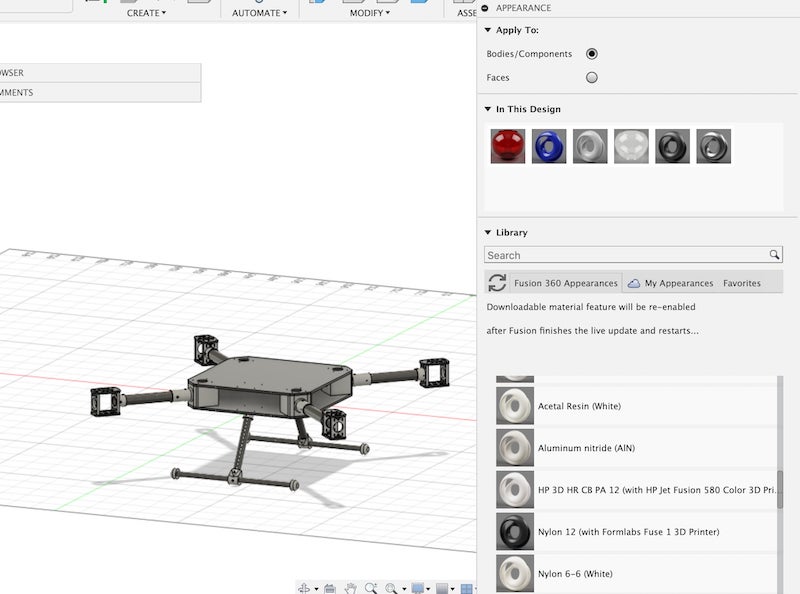
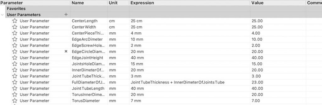
For 3D Design, I used Fushion 360 as I have prior experience with it from another class. To start with, I defined the parameters for my design. In Fushion, you can set store your measures in variables to be able to change them later without going back in timeframe. Here is a screenshot of some of parameters:
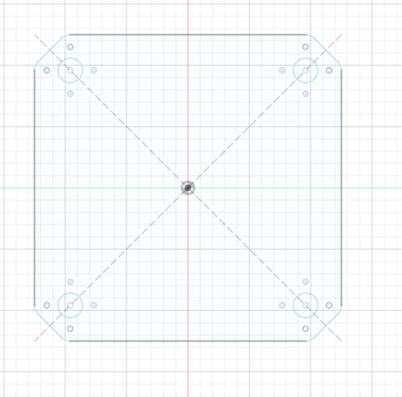
First, I created a sketch of the drone center using geometric shapes in the Create Menu in Fushion 360. Here is my first sketch:
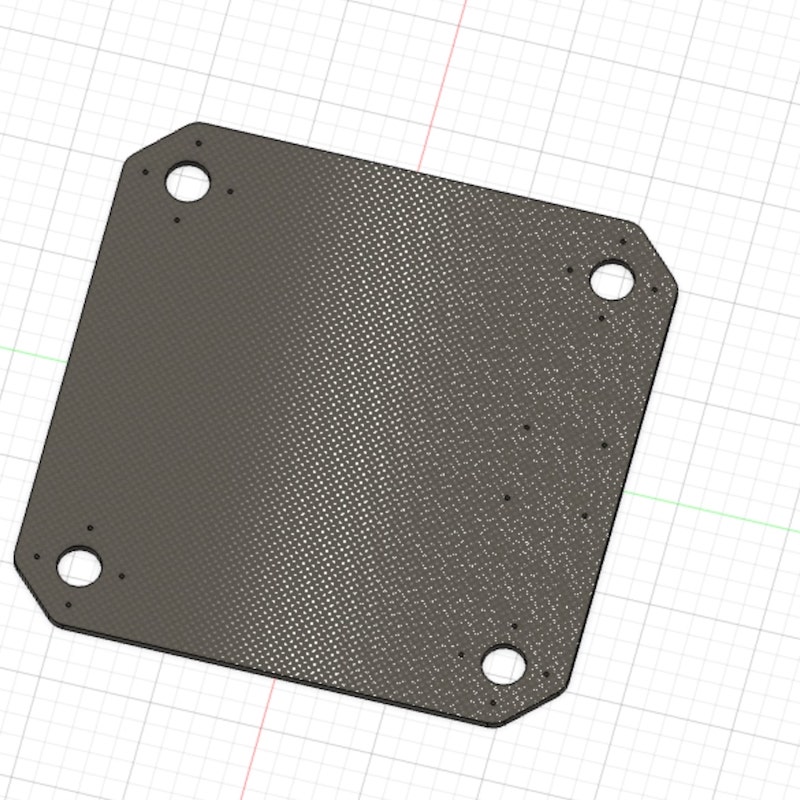
Second I extruded the sketch using the extrude operation to have a 3D plate that looks like this:
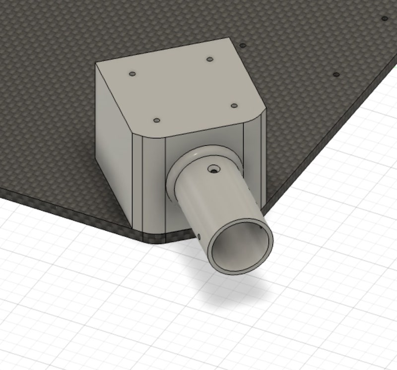
Then, I started designing the joints that connect the arms of the drone with its center. I created another sketch(bu this time on the surface of the plate I had already designed) at one corner of the plate and extruded it to look like this:
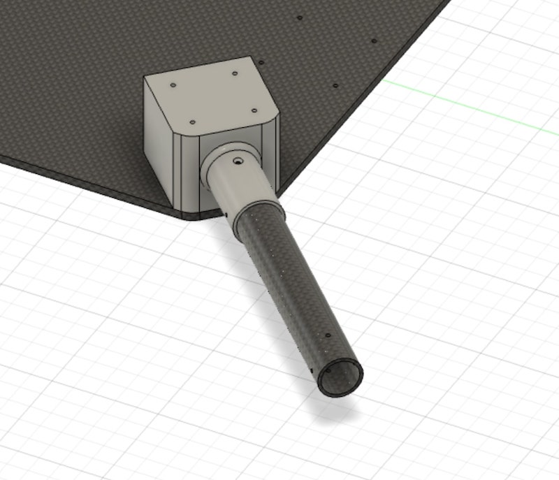
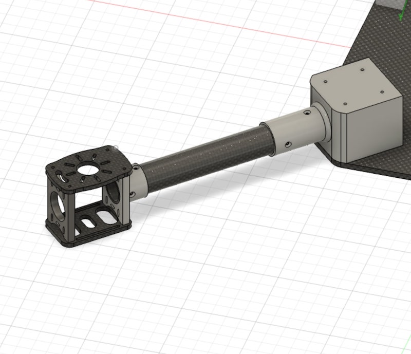
As we have the joint now, I started creting the arm. I created another sketch on inner part of the tube of the joint and extruded it to get the arm:
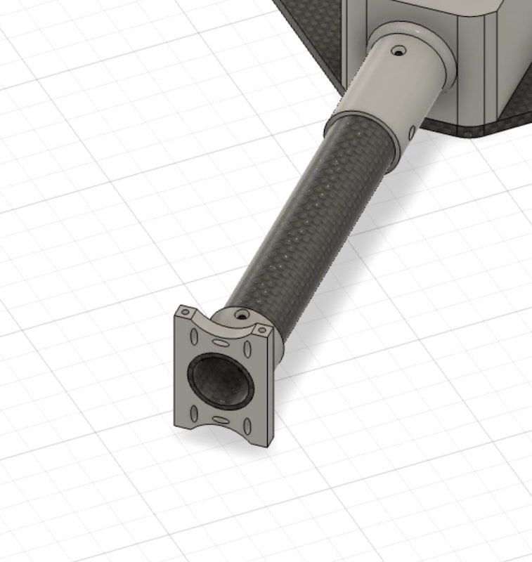
At the and of the arm, I created the motor base, where the motor will be attached. To create the motor base, I needed four pieces. The first is the joint the connects the motor base to the end of the arm like this:
The next two pieces are the motor are the top and bottom parts of the motor base. I also created skteches and extruded them:
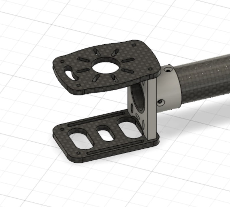
Then, I designed the final piece to form a full rectangle. I designed this by creating a copy of the piece corresponding to it and then moving the copy a certain distance till it fit. I have a full arm now!
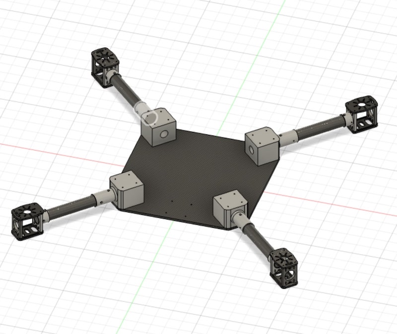
But we need four arms. Luckily, I did not have to design each arm seperately. Instead, I used the Circular Pattern feature in the Create Menu to make three additional copies of the whole arm and place them at the corners:
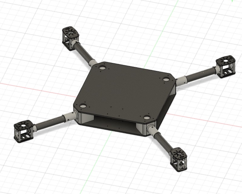
To have a complete frame, I needed a top cover. Since the top cover is identical to the bottom one, I just made a copy and moved it up till it fit using the Copy/Move tool(I pressed M to get it).
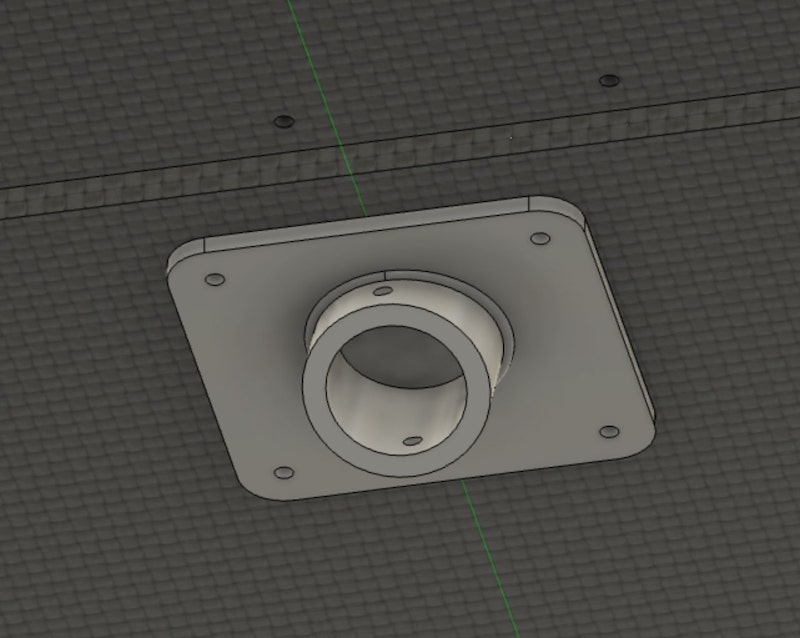
The final part was to design the legs. I first designed the leg joint that connects the leg to the bottom plate. I designed the designed square and a tube, rotated the tube 30 degrees using the Move tool again, and combined the square and the tube using the combine tool in Modify Menu to get this:
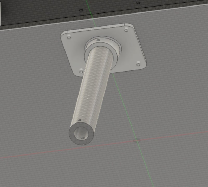
Next, I created a sketch on the bottom joint, drew two circles and extruded them to get a tube that represnts the leg.
Then, I needed another joint to connect the leg to the "foot" as I call it. I created a tube and a clylinder, combined them together, and then used fillet feature to give make it look batter:
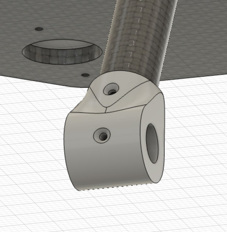
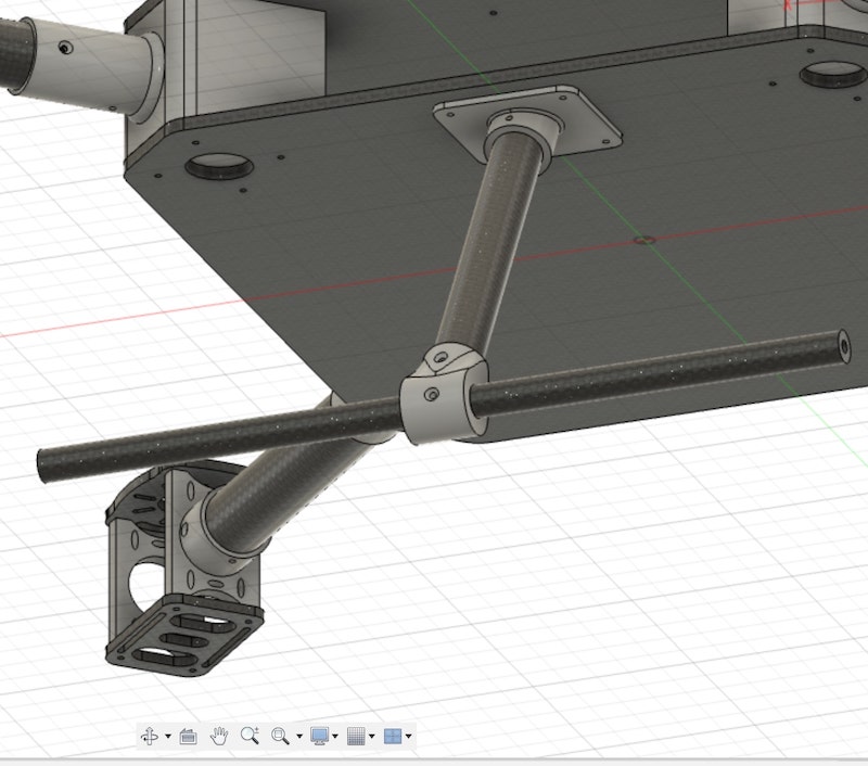
I created another tube to represent the "foot" and extruded it horizontally to pass through the hole in the joint.
To make the foot stable, though, I needed a toe at each side of the foot. So I designed a cylinder and used fillet again on it. Then, I used Circular Pattern to make another one at the other side:
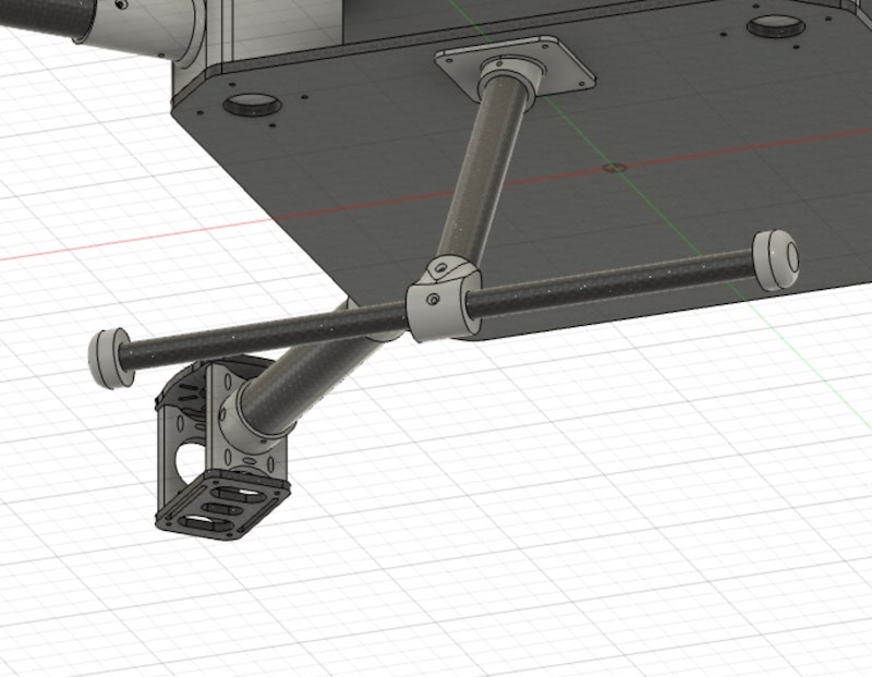
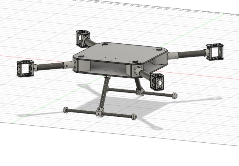
Finally, I used circular pattern again to make another leg at the other side of the drone. We have a complete drone frame now!!
I will be making the drone from carbon fiber, but I will 3D print the joints. In Fushion, I pressed A on my keyboard, chose carbon fiber and plastic, and dragged them to the corresponding components.