WEEK
THREE
Computer Controlled Cutting
Task for this week
Group Assignment
Characterize your lasercutter's focus, power, speed, rate, kerf, joint clearance and types.Individual Assignment
Cut something on the vinylcutter, design, lasercut, and document a parametric construction kit, accounting for the lasercutter kerf, which can be assembled in multiple ways, and for extra credit include elements that aren't flatGroup assignment
This week I have to make a parameteric design on fusion 360 and have to cut something on vinyl cutter. In group assignment we have to find out the Kerf of laser on different type of material. We also have to find out the best laser speed and power for cutting and engraving.
Then we have started working on group assignment . I have to find the kerf and speed and power requirement for plywood and MDF.
before doing so,ething let took a look of our laser cutting machine and how it is work.
About LASER Cutting
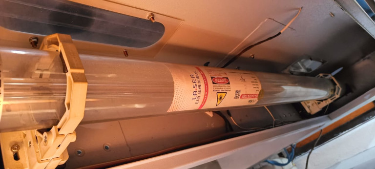
Laser cutting machine are used to cut and engrave material. There are different types of lasers cutting machine and we have CO2 laser cutting machine in our lab. The co2 laser consist a glass tube and it’s both ends are connected to supply. Its one end is connected to cathode and another is connected to anode. When we supply the power, atoms get energy and the electron excited and move from ground state to high energy state. After some microsecond they again come back to their ground state by releasing photon of lights and this is called Spontaneous emission. When this released photon are go in contact with another excited atom and then two photons are released at a time and this is called Stimulated emission.Hence the light amplification means increasing in intensity of light is caused by stimulated emission of radiation.
Additional accessories Of laser -
1. Chiller - It is used for the cooling process. Our laser are set to work when the chiller temp is between 22 to 27C.
The cooled water circulated in tube. Laser dont run without chiller.
2. Compressor - It is used to reduce smoke, dust and residue on lens. it also help the smoke to exhaust easily.
Machine Details
-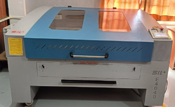
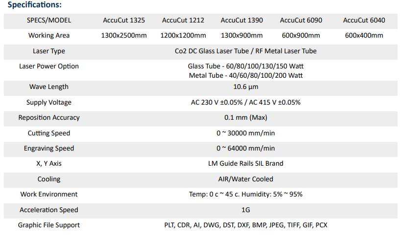
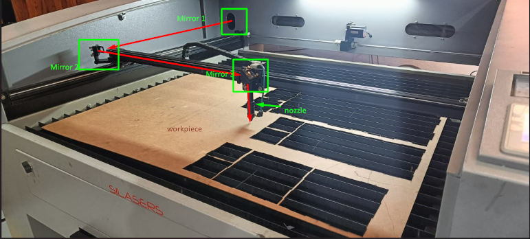
We have a Indian Manufactured laser machine. This laser perform cutting and engraving operation. Machine have 3 mirror arrangement
by which the laser reflects. All these mirror are set with angle of 45 degree because at 45 degree the light reflects at 90 degree by which we turn the direction of laser by 90 degree. All these laser are not concentrated so we use focus lens in nozzle to focus the all laser at a point. Then we have to set our focal length means the distance between nozzle tip and workpiece. This laser is make perfect focus when the distance between nozzle tip and workpiece is between 6mm to 7.25 mm.
I created a design in Inkscape which cut at different speed and power. Then I save the file in dxf format. I used LaserCad software for communication between computer and machine
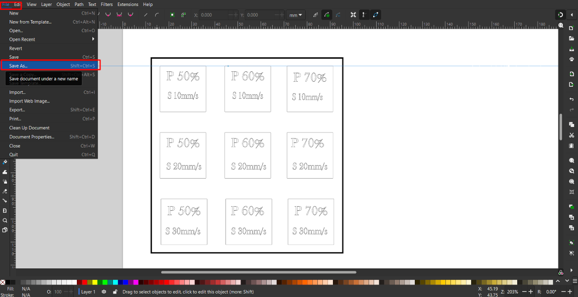
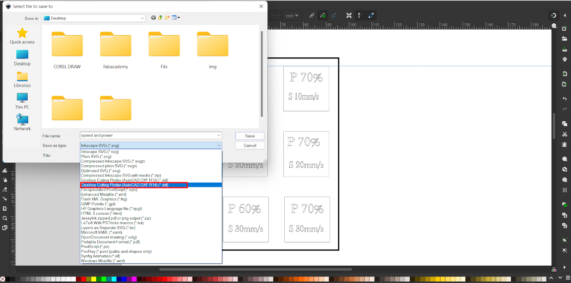
After open this software I import this file and choose different color for each box. Then I set different speed and power for different colors. Then I connect USB pin and download the ready file into the machine.
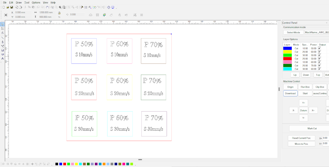
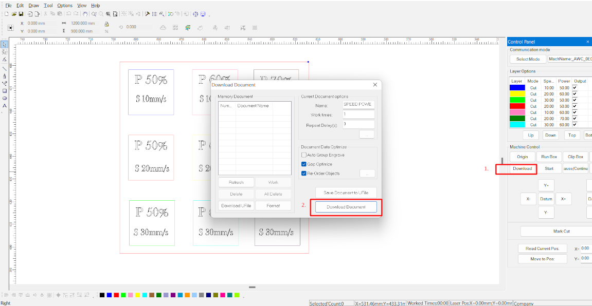
Now I cut different material at different speed and power to indetify the best power and speed for that particular material.
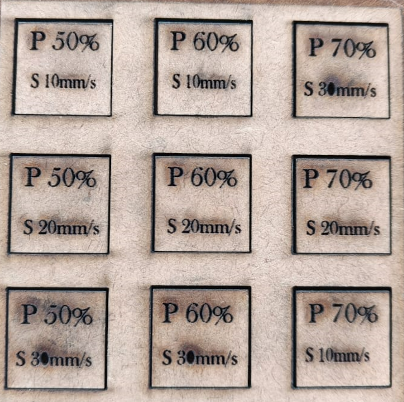
1.MDF 2mm
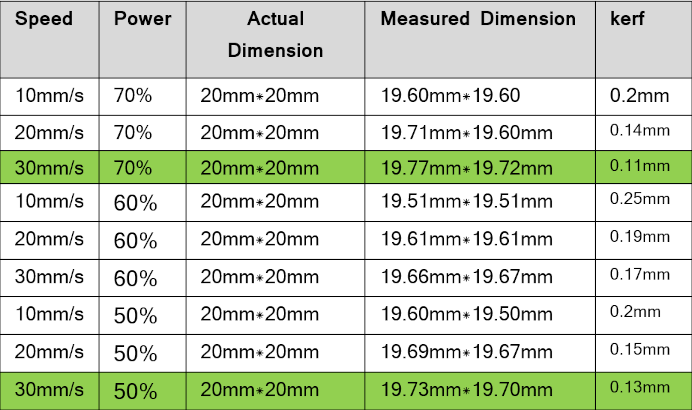
I used the MDF material of 2mm thickness and perform both operation of cutting and engraving and also calculated kerf for this. Kerf can be calculated by following formula = (actual size-measured size)/2.After find out the kerf I can make same dimension object I want by just including kerf value in it.
The result of cutting is given below
Result
This material cuts easily at the power between 50-70% and speed between 20-30mm/s . Between this speed the kerf value lies between 0.11 to 0.15mm, which is good for this Material.2. Plywood 6mm
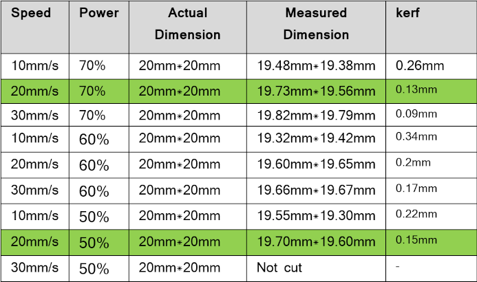
After the cutting of mdf I started cutting of 6mm plywood. I use same parameter and design to cut this material. The results are given below –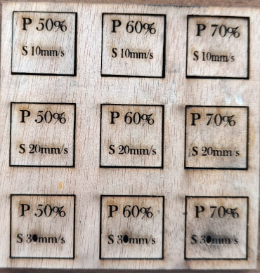
Result
- This material cuts easily at the power between 50-70% and speed between 20-30mm/s. between this speed and value the kerf value lies between 0.09 to 0.15mm,which is good for this Material.
After the cutting parametere checked I checked the engraving parameter for the different material of different size.
1.MDF 2mm
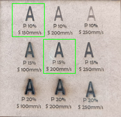
Result
The best engraving effect are seen at Speed between 150mm/s-200mm/s and power between 10%-15%2.Plywood 6mm
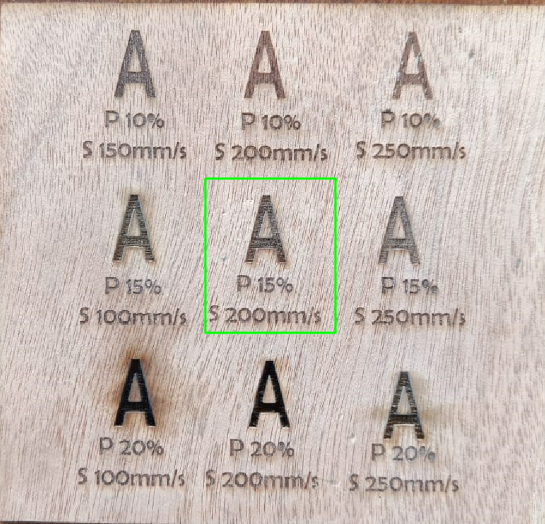
Result
For engrave the plywood we set the power between 10-15% and speed between 150-200mm/sClick here to know more about group assignment.
Individual Assignment
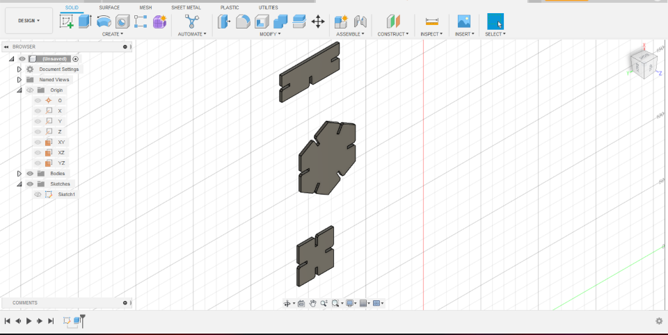
After doing work of group assignment, I started making a parametric model. for designe I used Fusion360 Software. I tried this software for the first time. After opening the software I have to select a plan where I have to make my sketch or design.After selection I took hexagonal shape and start making of my design for my Construction kit I desined three shape one is hexagonal, one is square and another is rectangle.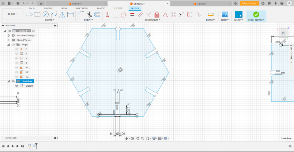
In hexagonal I gave five slot and chamfer them. In square I gave four slot and chamfer them and in rectangle I chose three slot I made some slots in each sketch and chamfer the corner.
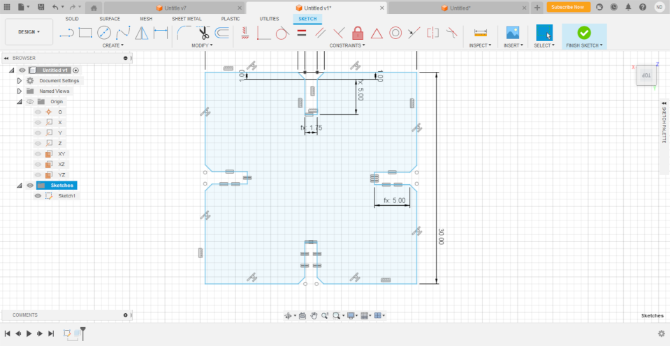
By chamfering the corner our cutting peice set easily in each other. Then apply relation on the sketch like equal, midpoint by wich if we can change a single side ,all sides will be changed if they have equally relation between them.
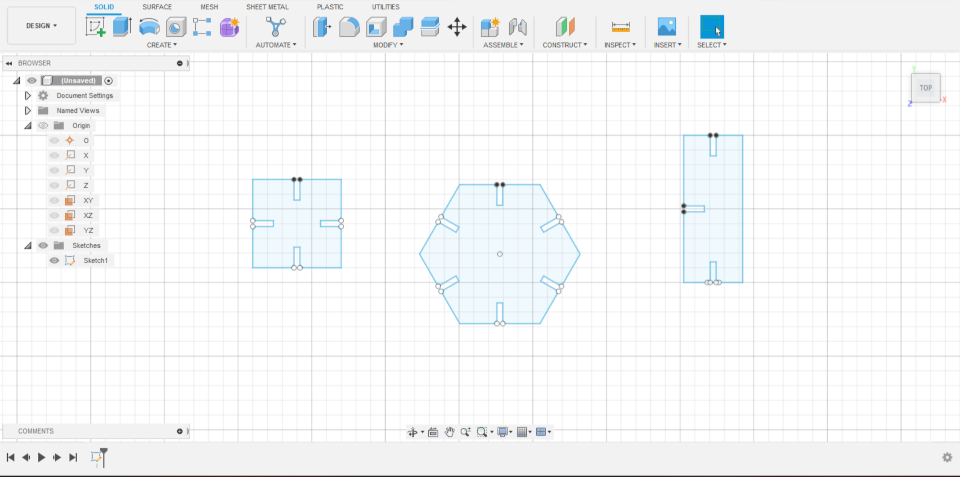
Then we have to make it parametrically. Parametric meanse if we designed a sketch for the material of 2mm and then we want to same dsign for material of 6mm. Then here parametric dimension are play an important role. Now I want two dimension may be paramtrically for further change in design for differnt material .Then I selected modify toolbar and at last see the option "change parametre".
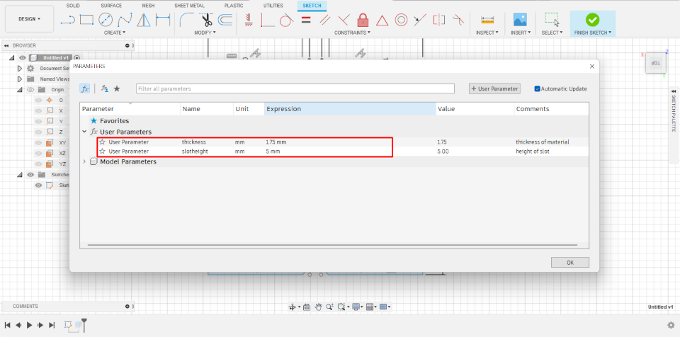
Then select this option and a a pop up window appear. Here we have to create a new parametric .Then click on user parameter and define the new parameter which we can change.
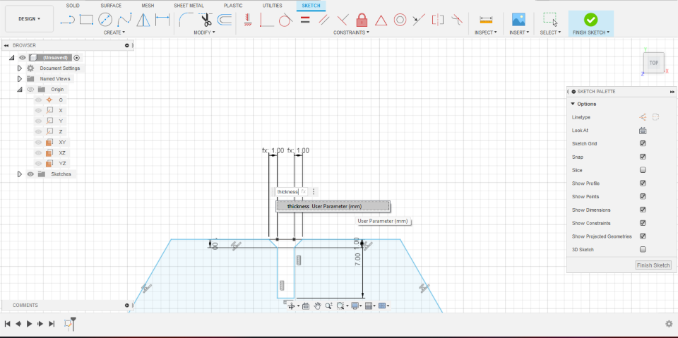
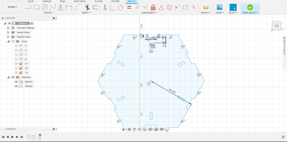
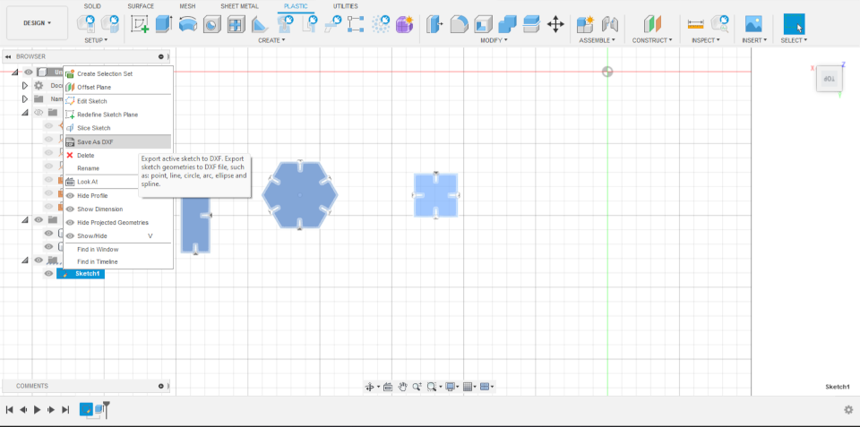
When my designed is ready then I export my designed in dxf file formate. For export, save the sketch and right click on the sketch and chose the "save as dxf" option. Then this file downloaded in our system. Then I opened my laser cad software and import this file in lasercad. Then I created a multiple replica of given sketch and start cutting.
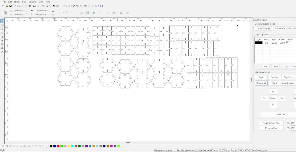
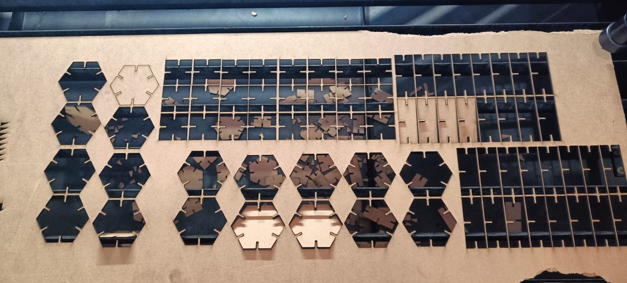
Now after the design I cut the design 2mm MDF sheet by laser cutting machine.
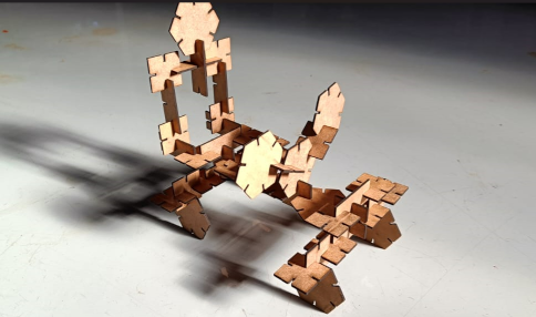
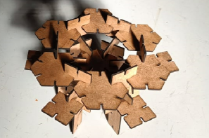
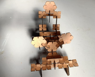
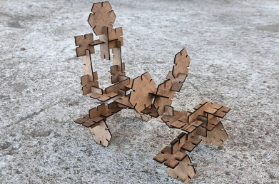
After I started making different shape from them. I made a monster vehicle from this different pieces. Second we made a tower structure by joining same pieces in different ways.
Vinyl cutter
After that I have to start working on Vinyl cutter. Vinyl cutter machine is 2D machine which cut our desined on paper shaped material. We have Roland SC15 machine in our lab. This machine have cutting tool and we adjust this tool with thickness of paper or foil.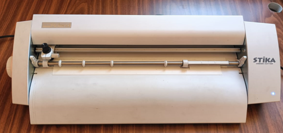
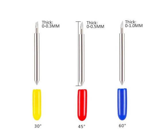
So I took off this tool and set it ccording to my vinyl paper. vinyl paper have two layer, one is adheshive or colored layer and another is suppoertive layer. at the time of cutting we have set the just like it only cut the adhesive or colored layer, not cut the supportive layer. in cutting tool, a cutting blade is situated. The tip of these blade have some angle on which it cutting properties are depends.Mostly we use 30 ,45 and 60 degree angle cutting blade.
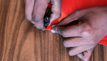
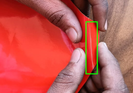
Then I used solidworks for making sketch of half circle and then I save the file jpeg formate .Then I open the machine software named Cutstudio and import the designed file in it. In the cam software I created replica of it and adjusted their size and start cutting. I cut different designed in different vinyl paper.
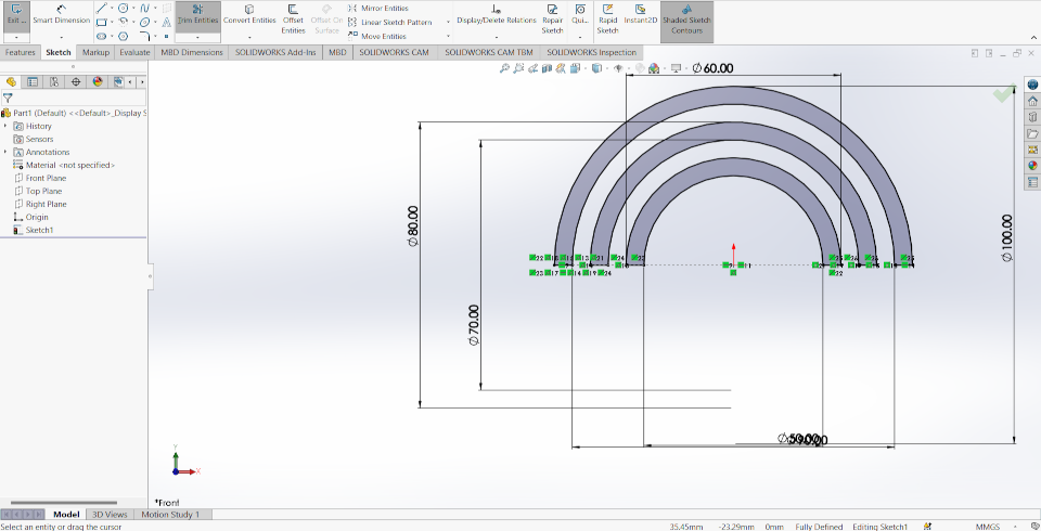
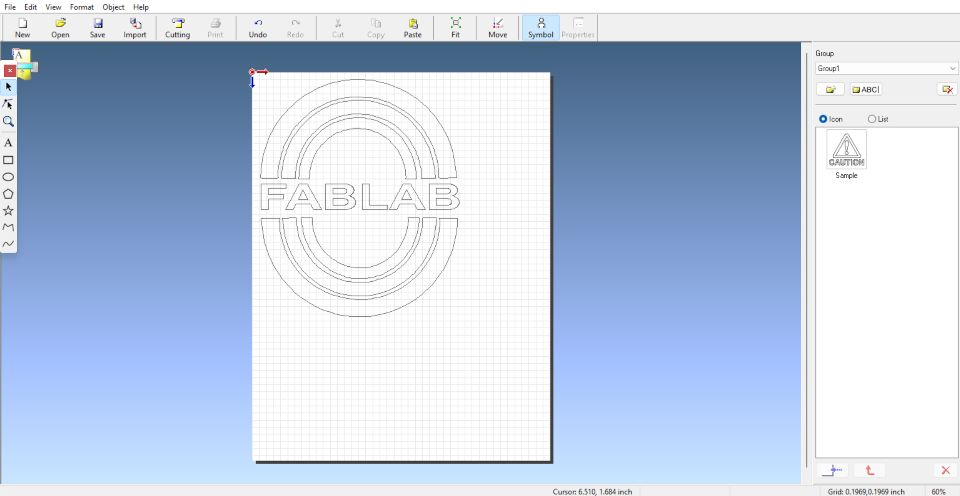
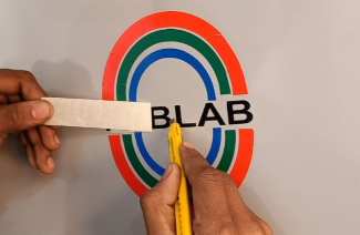
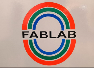
After cutting I remove the cutting vinyle by paper tape and stick it on my Fablab almirah beacause I already have a logo on my laptop.We remove all the cutting vinyl properly and and our designed logo is ready .
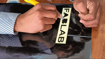
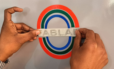
Learning outcomes
-I learned about parametric design.-I learned about kerf for the different type of material for my machine.
-I learned about vinyl cutter machine.
Click here to download the original files
Click here to know more about group assignment.