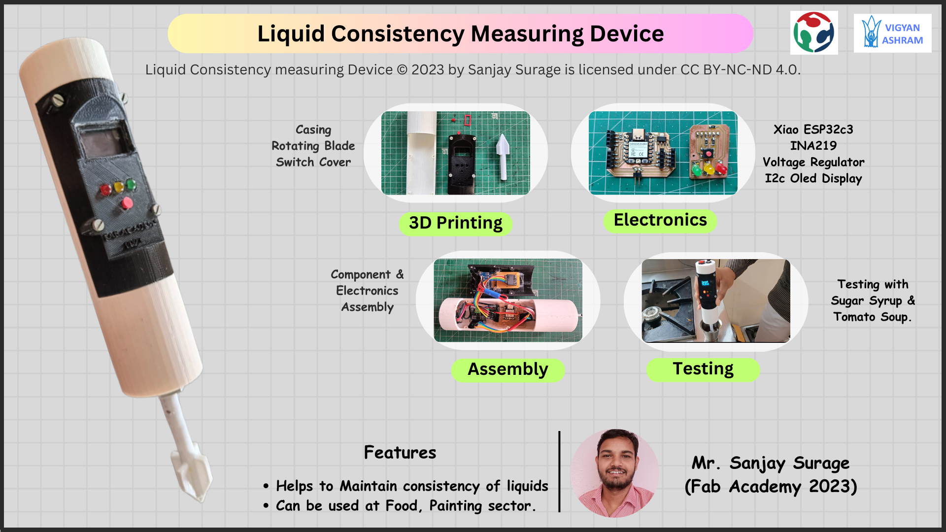
I am making a project which will check the liquid prepared in the kitchen and tell whether it is proper or not. It will measure the thinness and thickness of the
liquid.I am creating this project right now to measure two things. First measuring sugar syrup in food lab and second measuring tomato ketchup in kitchen.
I am using motor in this project. When this motor rotates inside the liquid, it will take more current because shaft oppose the shear force of the liquid
Then this current will be measured by the sensor and then we will see its data on the display.Before measuring both these things, I have to calibrate my project.
For that I will take perfect sugar strainer and tomato ketchup.And then I will rotate the machine inside them and note down the value of current. Then I will
give the condition in the microcontroller.Then whenever we measure these two liquid, it will give us the data by mixing it with the recorded current value.
Motivation behind Project selection
There is a foodlab in Vigyan Ashram. Where the things to eat are prepared. Sugar syrup is used more in making all those things.Sugar syrup is used in
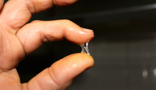
making most of the things.To make sugar syrup, we have to heat sugar and water and after some time it becomes ready.To check whether the sugar syrup
is cooked properly or not, we take it between two fingers and check its stickiness.So, due to the heat of the sieve, sometimes it is difficult to check
it and it also feels hot in the fingers.
So I thought of making a project to check whether the sauce is made properly or not.I got the same problem from
the kitchen of Vigyan Ashram. When he makes tomato ketchup, sometimes it remains thin and sometimes it remains thick.So I understood the problems of both
these places and thought of making a project. Which will measure their thikness and thinness and tell us correctly that this thing is made or not.
Who's done what beforehand?
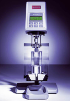
To measure the liquid consistency, there is a device called Rheometer which is available in the market. Along with this food product, many things are measured.
The way to do it is simple. There is a ring in its shaft which rotates through the liquid.When this rig rotates in the liquid, the force tightens due to which
the motor has to apply high torque and high current is required for high torque.So this gives the viscosity of the material according to the current and the shaft
rpm. The reason for this being very expensive, not everyone can buy, that's why I am designing my project by giving the principle of its current measurement.
My project will only be able to measure the consistency of some selected liquids.
For tomato sauce and ketchup, their consistency are measure by the device called Bostwick Consistometer.Actual consistometer is a device that measures
the flow consistency of any liquid.It is a simple device but very expensive.It is mostly used to measure the consistency of tomato ketchup and sauce.
This tells us about the consistency keeping in mind the flow of Kethup and Sauce. Inside it there is a chamber with a gate attached to a spring.We fill sauce and
ketchup in the chamber, after that we open the gate instantly with the help of remote. After that it measures the flow distance in a beyond defined time.And
then according to the distance, we can tell about its thickness and thinness.
Working priciple
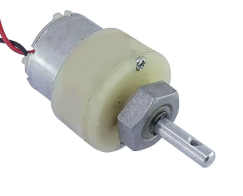
I am gonna using a geared DC motor. The machine required some constant current to move freely. But when we Oppose the motion of the motor shaft,
The current requirement of the motor gone increases. Because at this time machine produce high torque to rotate. So when we deep the Shaft in liquid
the low thickness liquid provide less opposing force to motor shaft but high thicker liquid provide high opposing force , So machine require high Current to
rotate.So we can measure the consistency by calaculating the value of required current.
Here is the video which shows the result when we oppose the rotion of shaft.
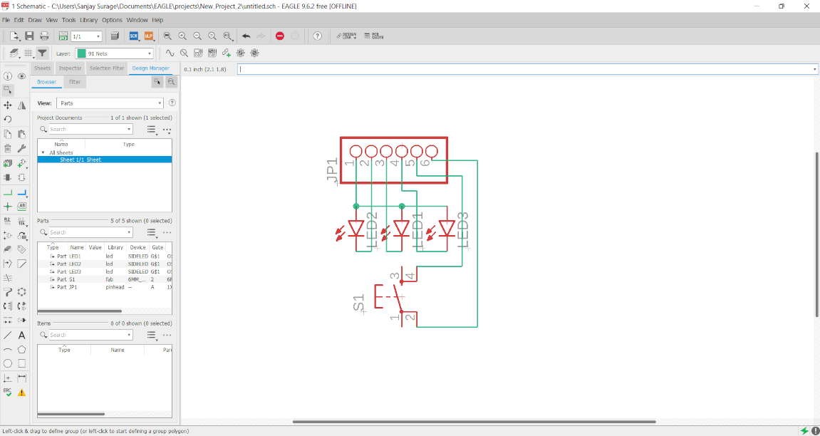
schematic
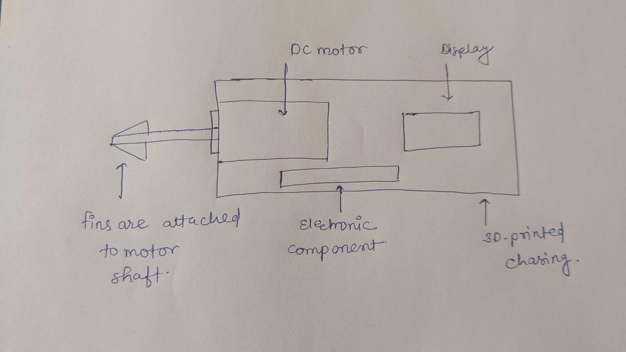
So I make a schematic design of my project. Basically it will be circular in shape in which one side we mount the motor and another side we supply the power.
Inside it there will be a microcontroller which control all this process. I used a current measuring sensor and its data is read by the microcontroller and Then
display the result on the display.
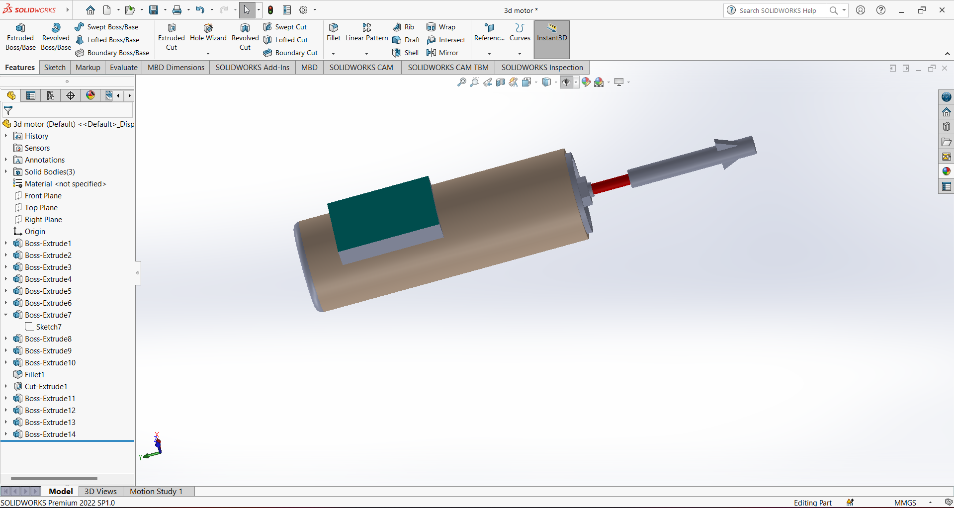
3D design
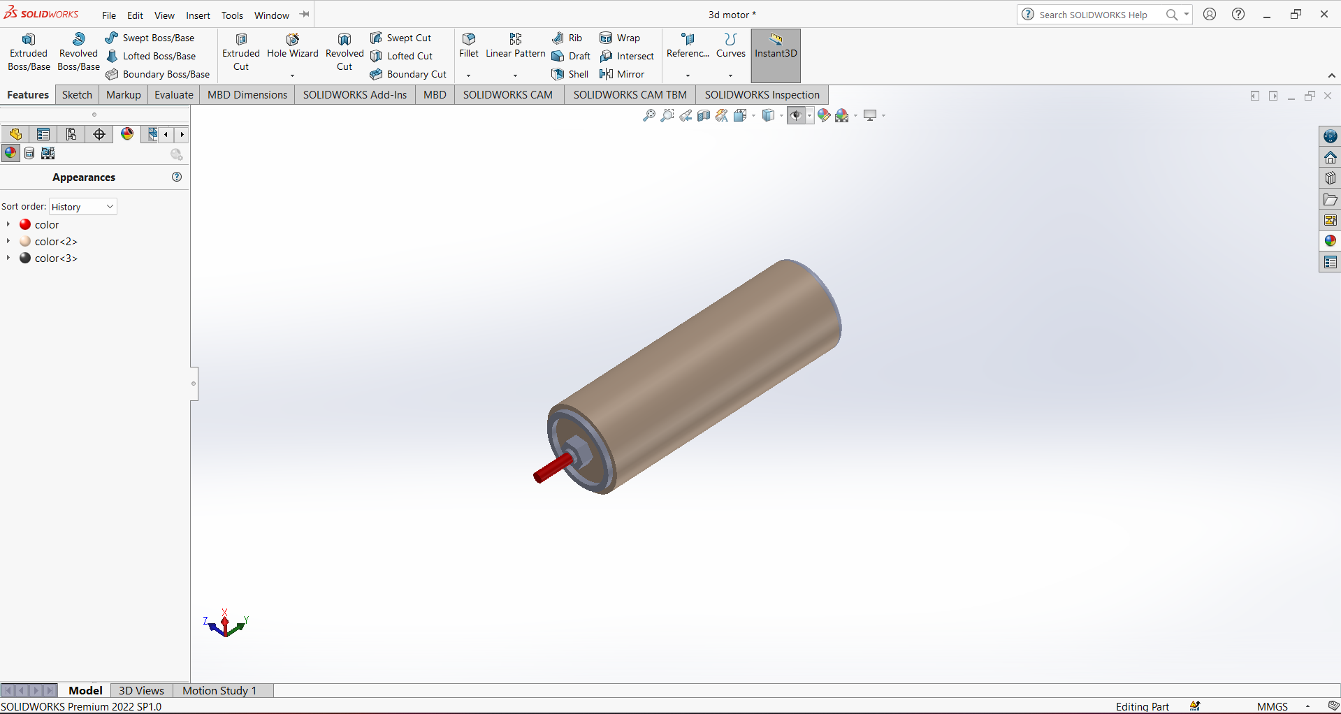
after the project sketch I tried to design my project in 3D . this is first design my project which I designed in solidworks.
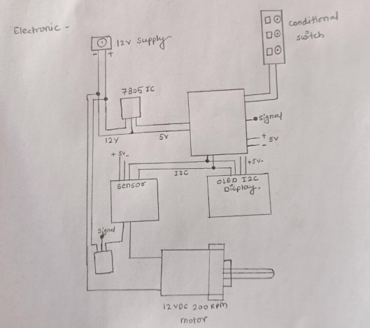
Electronic Schematic
So After that I roughly design the electronic schematic on the paper to get the Idea of PCB milling. So I designed the
schematic which is shown below.
My project Steps
After all this I planned my project process means which I do first.
• STEP 1 : COMPONENT SELECTION • STEP 2 : PCB DESIGN AND MILLING • STEP 3 : PCB AND COMPONENT TESTING •STEP 4 : FABRICATION AND ASSEMBLY •STEP 5 : CALIBRATION • STEP 6 : FINAL TESTING
STEP 1 : Component Selection
I selected the component and purchased them . The details of component used are given in below table.
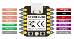
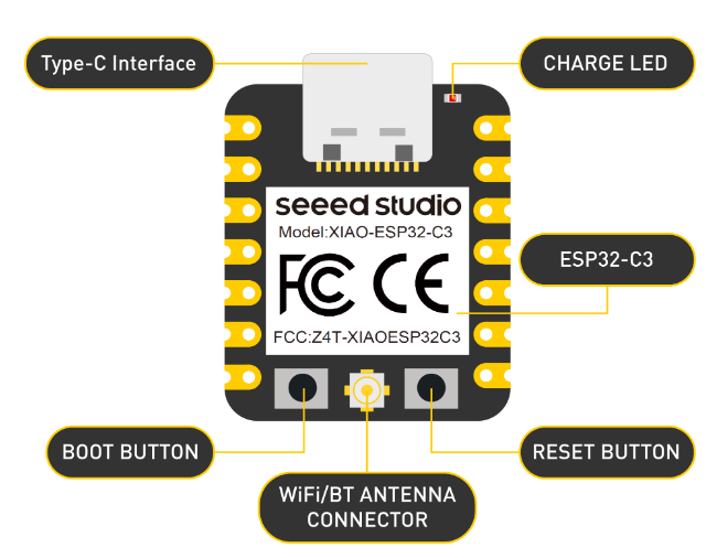
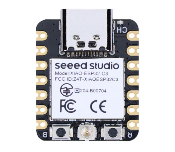
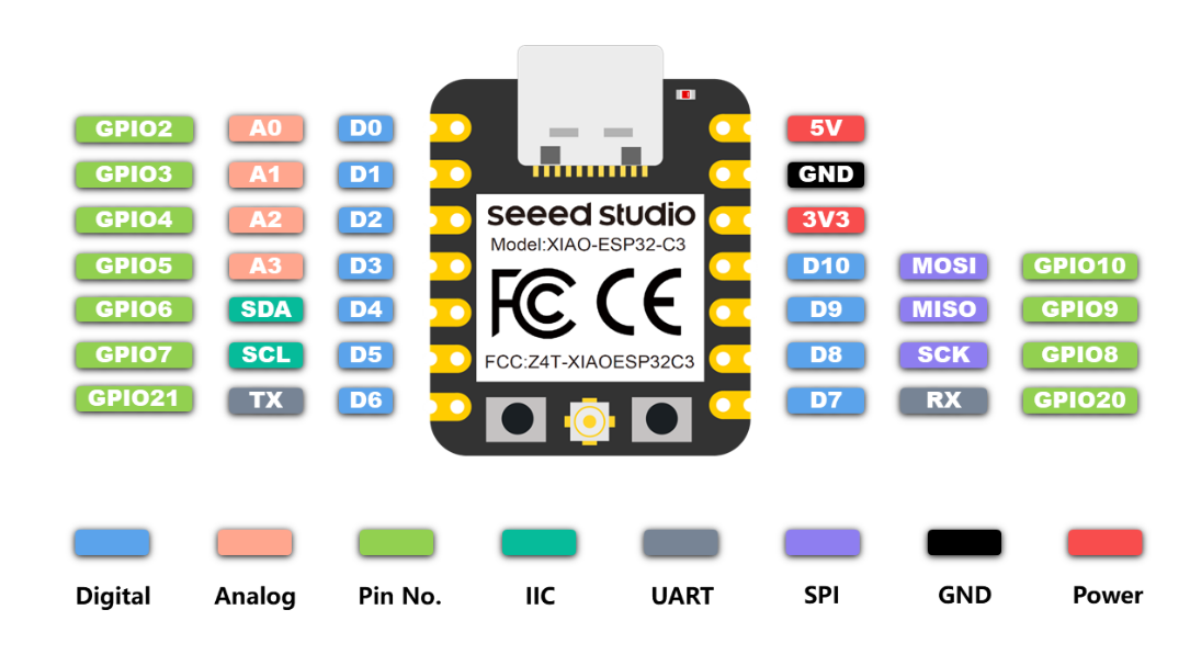
This time I used a Xiao Esp32c3 board. This is the tiny board and its size is 21*17.5mm. This xiao board come with integrated ESP32 C3 chip which operate at 160MHz. This intigrated chip have 2.4 GHz WIFI system and bluetooth 5.0. It has 400 kb of SRAM and 4 mb of flash memory . The chip required the voltage of 3.3v@200mA. But we can give the 5v supply. It can work in -40C to 85 C temperature range.
Pin configuration-
1.Universal asynchronous receiver-transmitter(UART) - 1
2.I2C- 1
3.IIS - 1
4.SPI - 1
5. GPIO -11
6. ADC - 4
It also have a reset and boot button in it.
•12V DC motor
The 12V DC motor operates at a speed of 200 revolutions per minute (RPM). It runs on a 12-volt direct current power source.
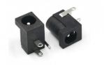
•12V Female connector
This female connector are used for the supply the 12 v from the adaptor.It is commonly used in various applications, such as automotive, marine, electronic devices and science projects.
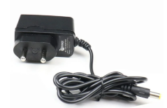
•12V 1A adopter
I also used a 12 V 1 A adoptor for power supply.
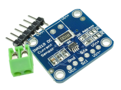
•Current sensor
I am using INA219 current sensor module. It also measure the power and voltage consumption. It work only for DC. It can measure the maximum voltage of 26 V and can measure the current of 3A. It is very precise in measuring the current.
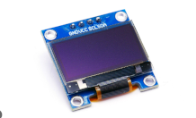
•OLES I2C display
OLED i2c Display is a type of display that utilizes organic light-emitting diodes (OLEDs) and communicates via the I2C (Inter-Integrated Circuit) protocol. It provide high contrast, wide viewing angles, and low power consumption. Its tiny shape make suitable use of this display in small projects.
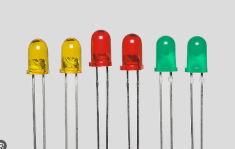
•5mm Leds
Leds are light emitthing diode, which glow when we supply power to them. This leds are energy efficient and required the the voltage of 3V for the operating.
STEP 2 : PCB DESIGN AND MILLING
I have to design a pcb. So for this I chose eagle software. Eagle is owned by autodesk. You can download it from The autodesk website. After download
login with your fusion 360 account Id password in Eagle.
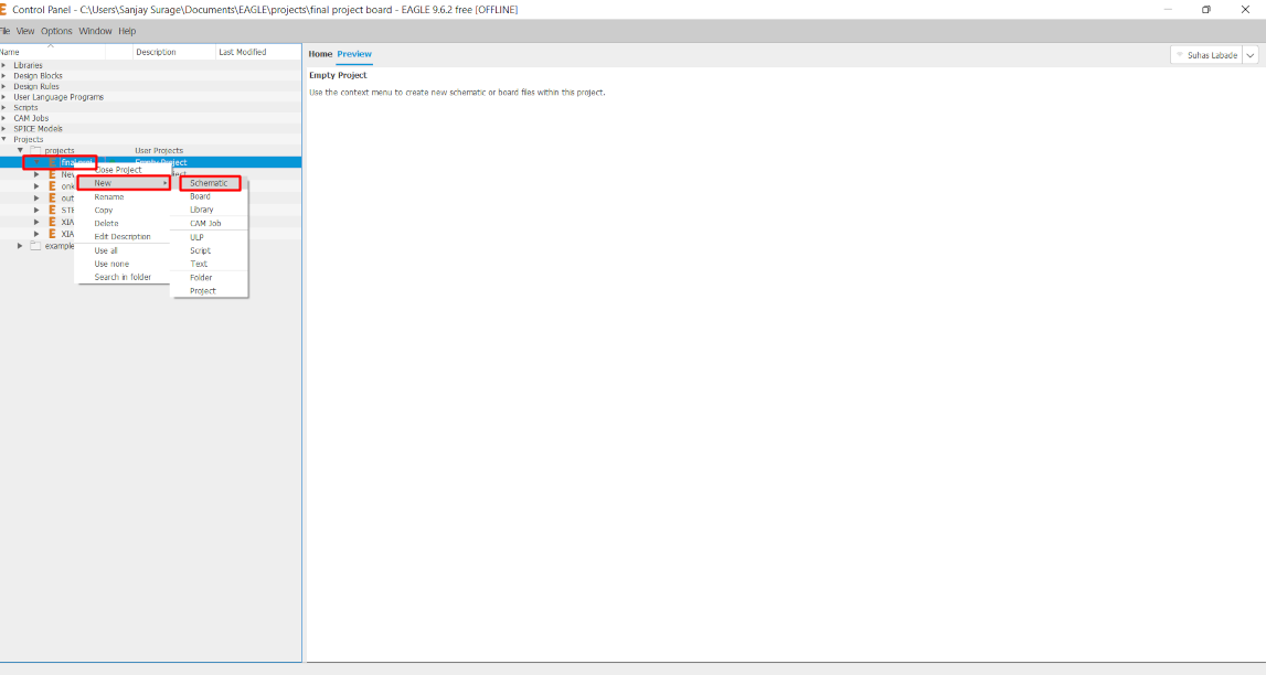
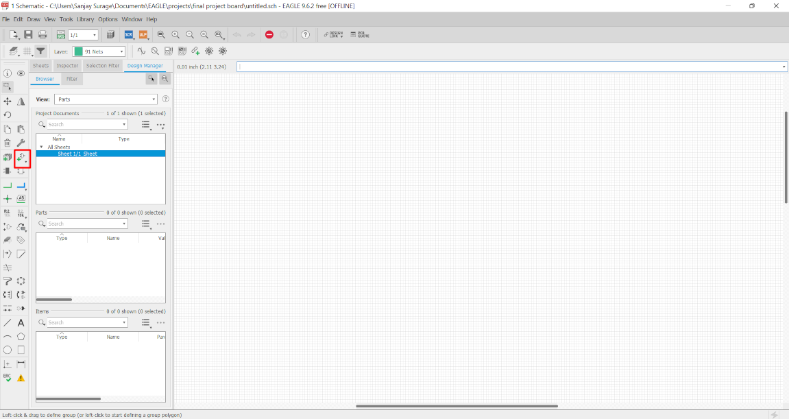
Open The eagle Software and then Follow the steps to create a new project work.
Go to file >> New >> Project then Enter
Then a new window open. Here we have rename our project name. After this right on them follow this Process.
Project (right click) >> New >> Schematic.
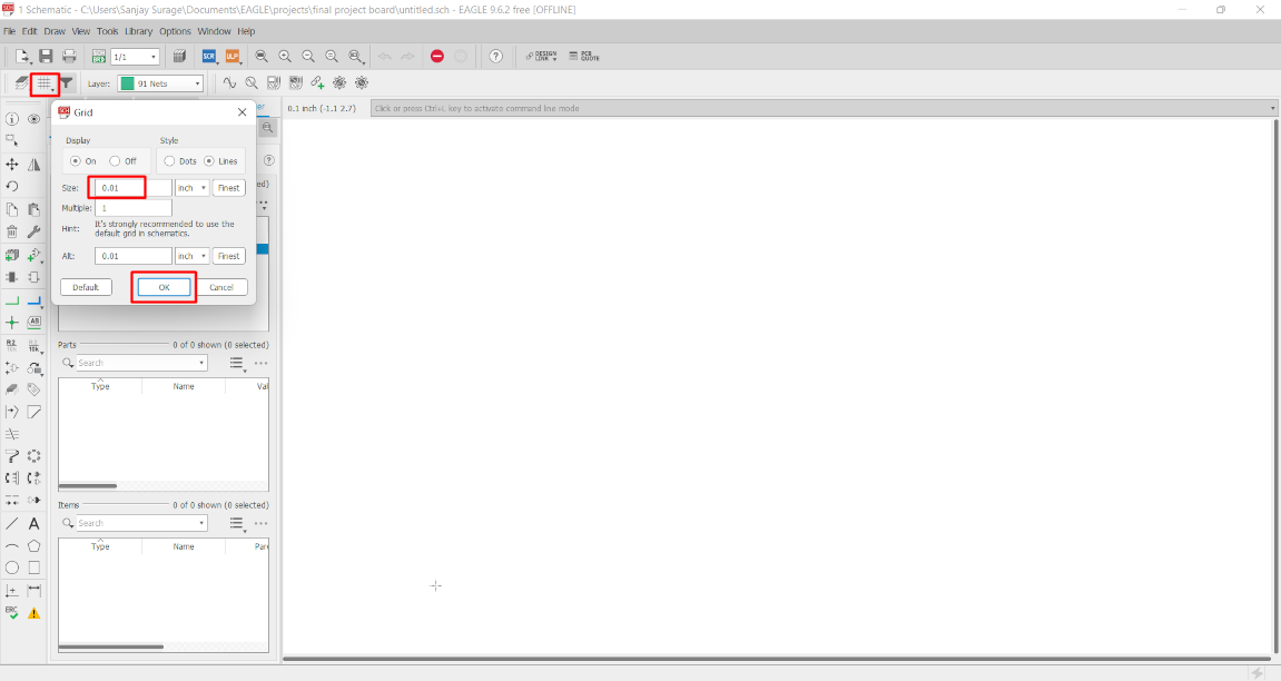
In schematic we have to add parts and add connection between the parts.
After that I click on grid option and then selecct grid size of 0.01 inch for thw schematic. Grid help us to component arrangement and the connection between them.
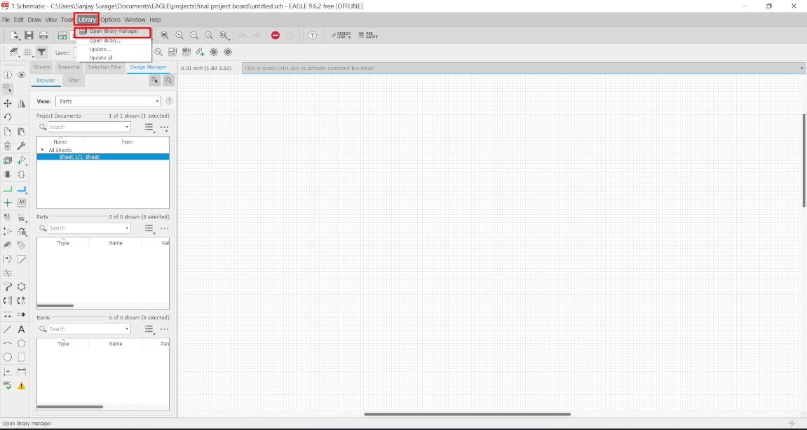
Library update on Eagle
Whenever we have to design a PCB with new board or IC. We have to add its Library on eagle by which we can know the dimension of that board and
proper positions of the pins with details.
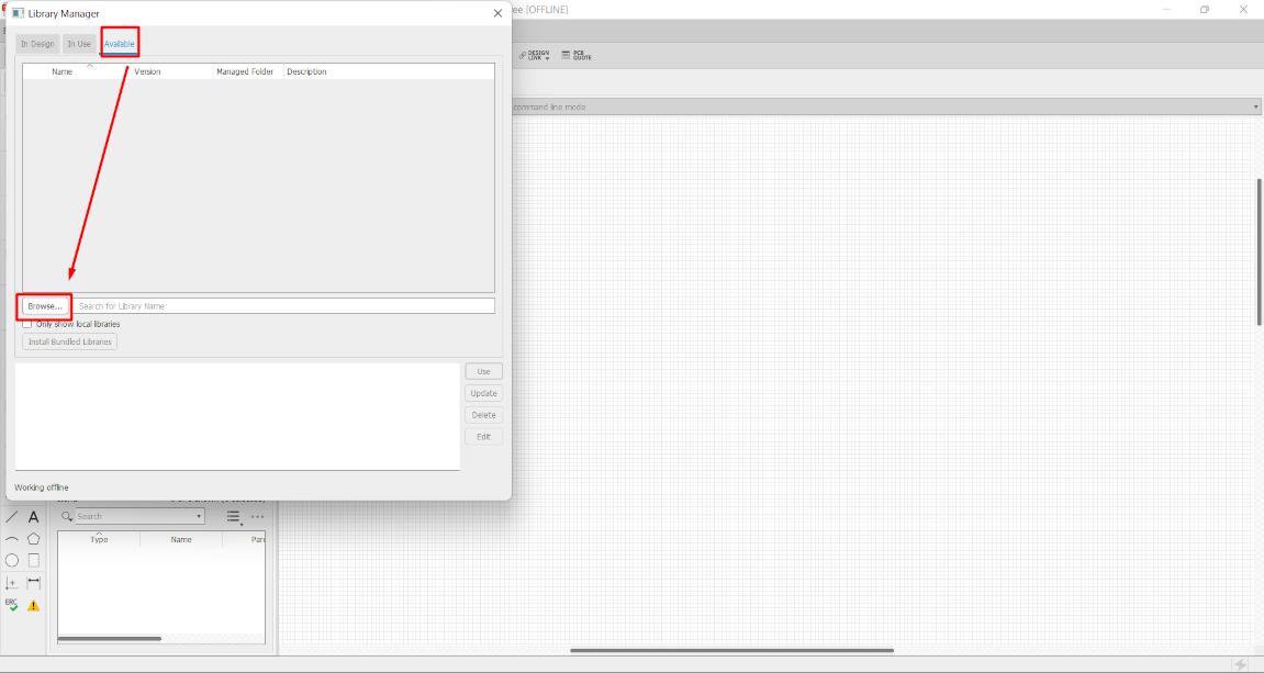
For library update-
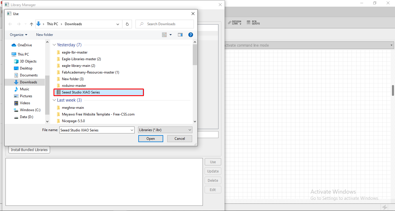
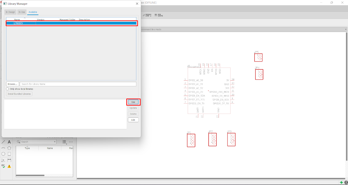
Go to Library >> Open library manager >> Available >> browse
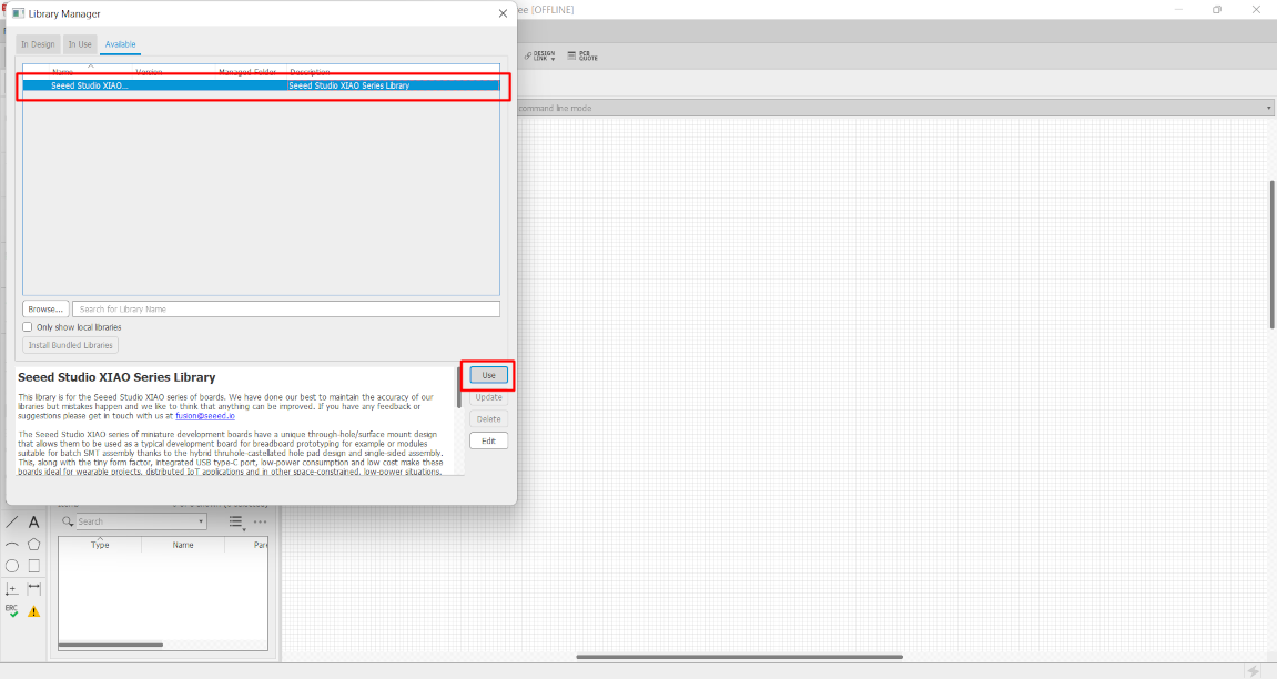
After the library selection click on it and click on use. After that this library available in add part section.
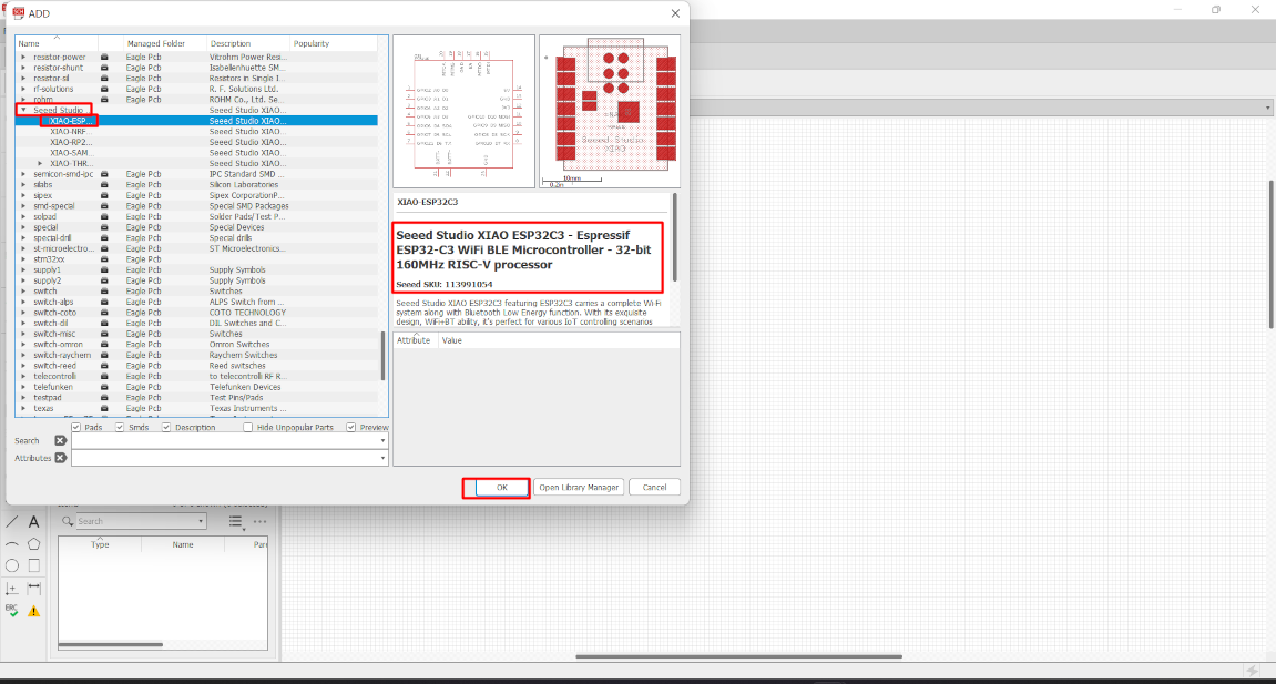
After adding library now we add the part. To select the parts go to the Add part option or simply write "add" on search bar.
Here I selecte seeduino Xiao and then select XIAO esp32c3 board.
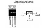
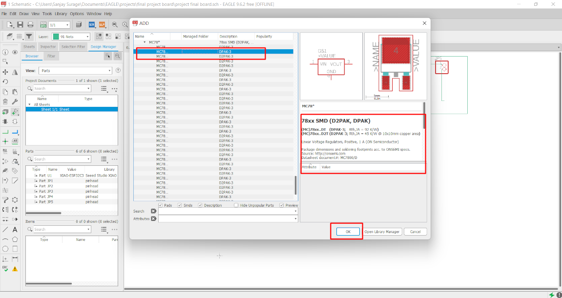
After that I need a Voltage regulator to convert the 12V into 5V. So for this I chose 7805 Voltage regulator in SMD. So the library of this regulator is not available in the Eagle. So I download the library and add it in Eagle.
Then again go to the ad part and select the voltage regulator.
Then I select four Pin header of 4 pin and one pin header of 2 pin. The selection of pin header are based on the pin configuration of sensor , display , power and led connection.
Now we have to arrange this part. Every part have plus sign in it. click and press the plus sign and then we can move the part.
When we select plus sign and right click, a part editing toolbar is open. By this we can move, rotate , delete and pattern can be given to that
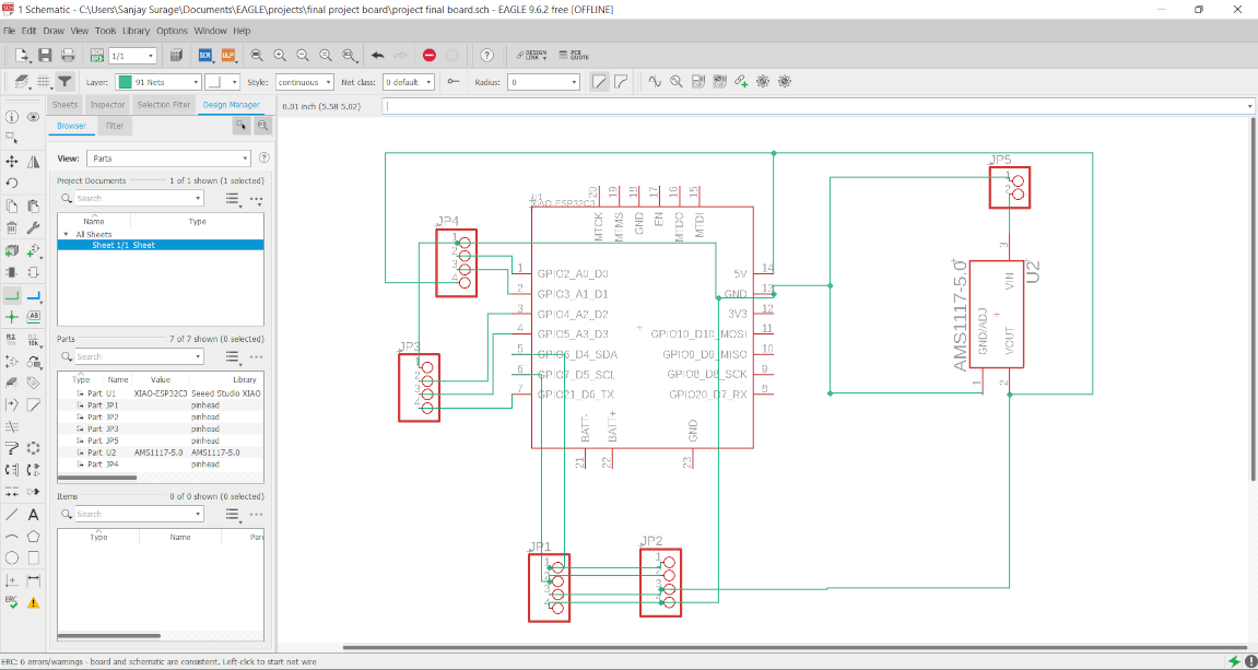
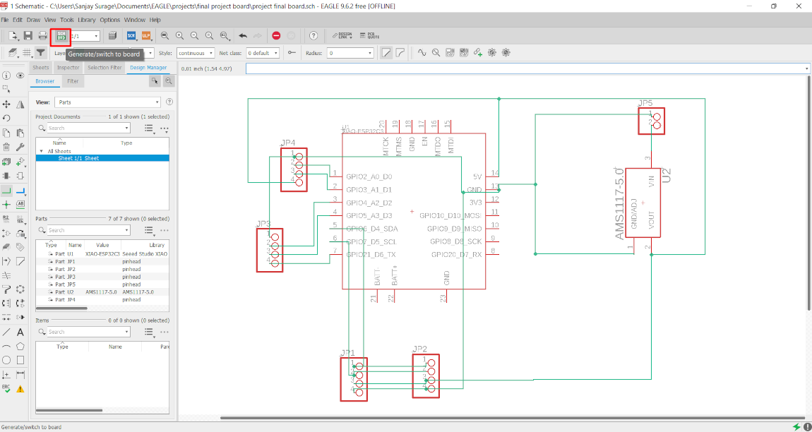
part. After arranging the part . Now we have to make conection between this parts. For making conection, simply go and select Net command as shown in Image
Then we simply make connection.
Whenever we writing a code and then we complie them for finding error . Just like that in electronic design we also have to check and follow the
electronic rule. It give error when the net is overlap and when joint are not proper connected. So for check this file
Go to Tool >> ERC (ERC is the tool to check schematic design ).
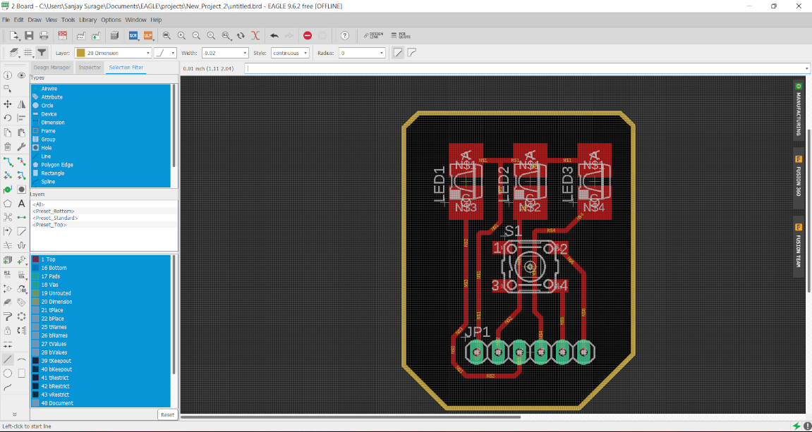
After solving all this error and warning we switch from schematic to Board. For this select option which shown in image. after this new board window is open
Schematic to Board
One by one select the part by clicking on its plus sign and drag them into rectangular box
We arrange this part in proper way. This is the final position of the parts in Board
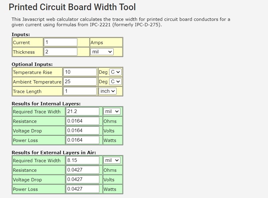
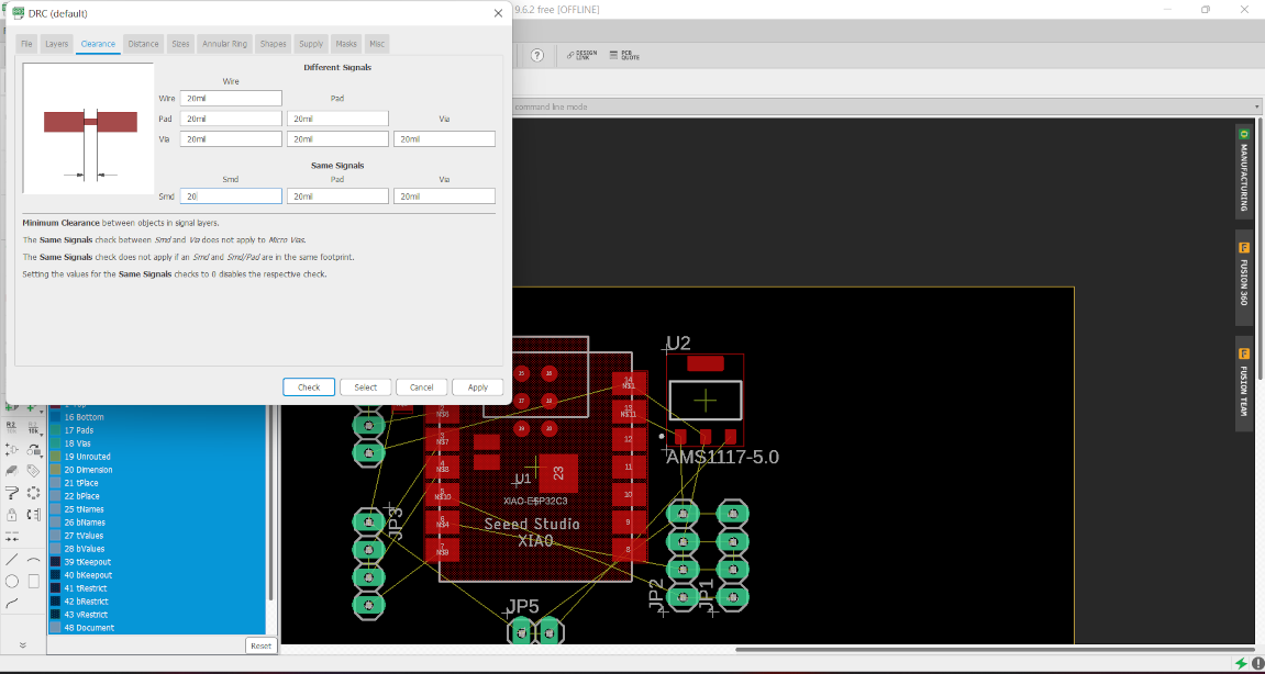
Just like schematic we also have a DRC in eagle which is a Design rule check tool. Here we can set the clearnce between two patways, Size of the pathway and
many more. To calculate the width of traces according to current value flow. So we used a online PCB width calculator. we calculate the width for 1A current,
Beacuase we use only LEDs in the board which requirde current under 1A.
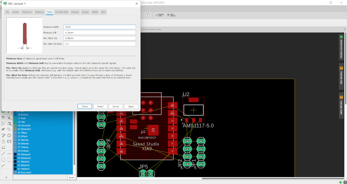
After calculation, We have to set the trace width of around 20mil. So go the tool and select DRC here.
Now I change the value of width and other parameter.
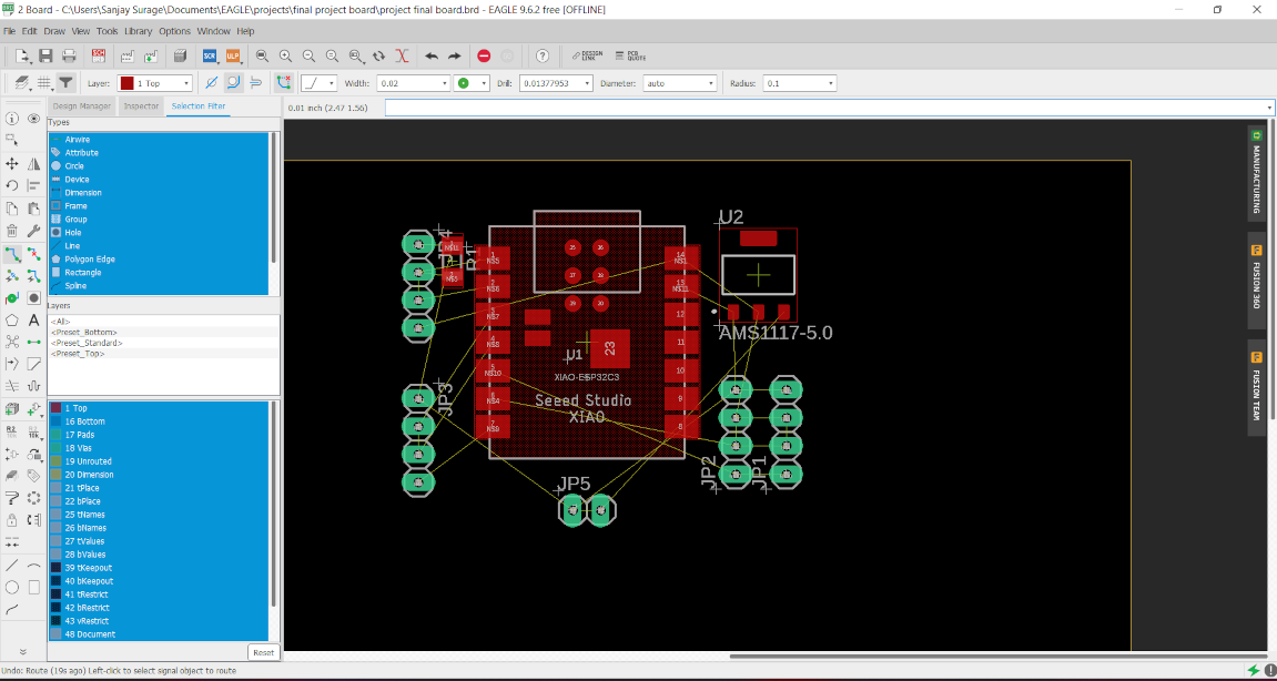
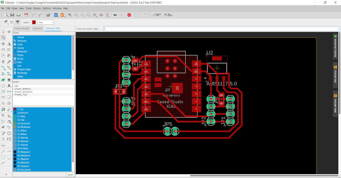
Then arrange the component properly and select the Route airwire option to make betwwen the component.
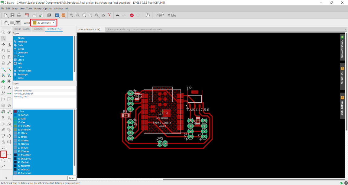
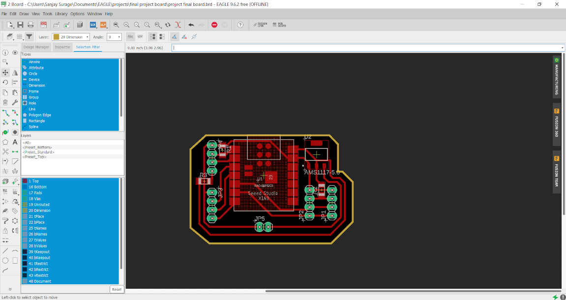
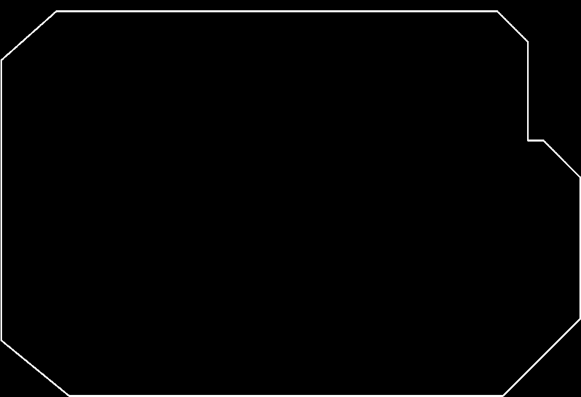
After that I select the dimension layer and select a line option and then draw the boundry of my PCB.
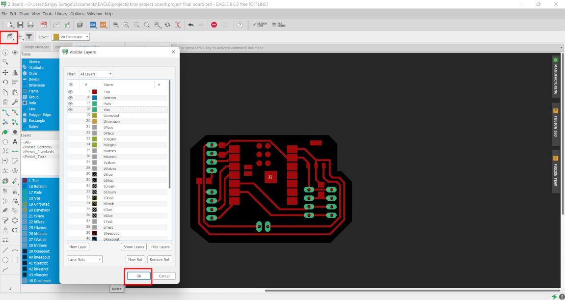
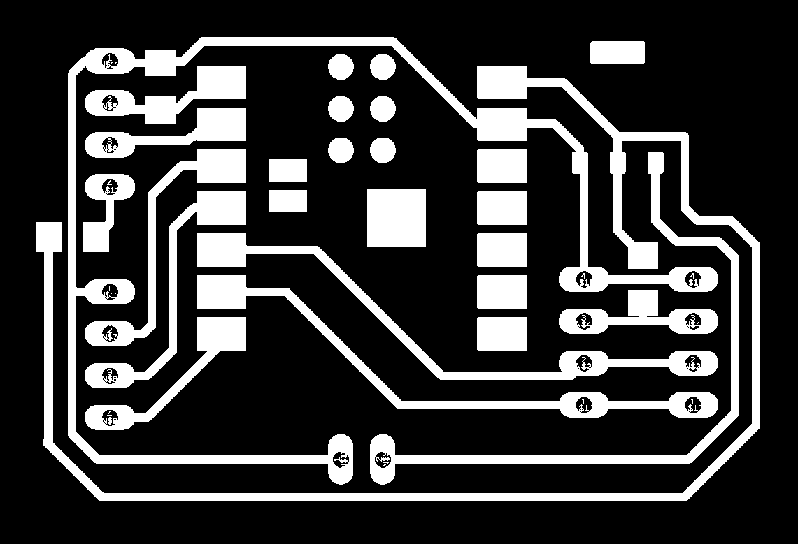
Now the PCB design is completed. We have to export this PCB file in png formate for the milling operation. So we have to select two different files. One is for milling and another is cutting. So Firstly I exported the milling process file . So for this Go to the layer option and hide the all layer then make visible the Pad, Bottom, top layer and press ok.
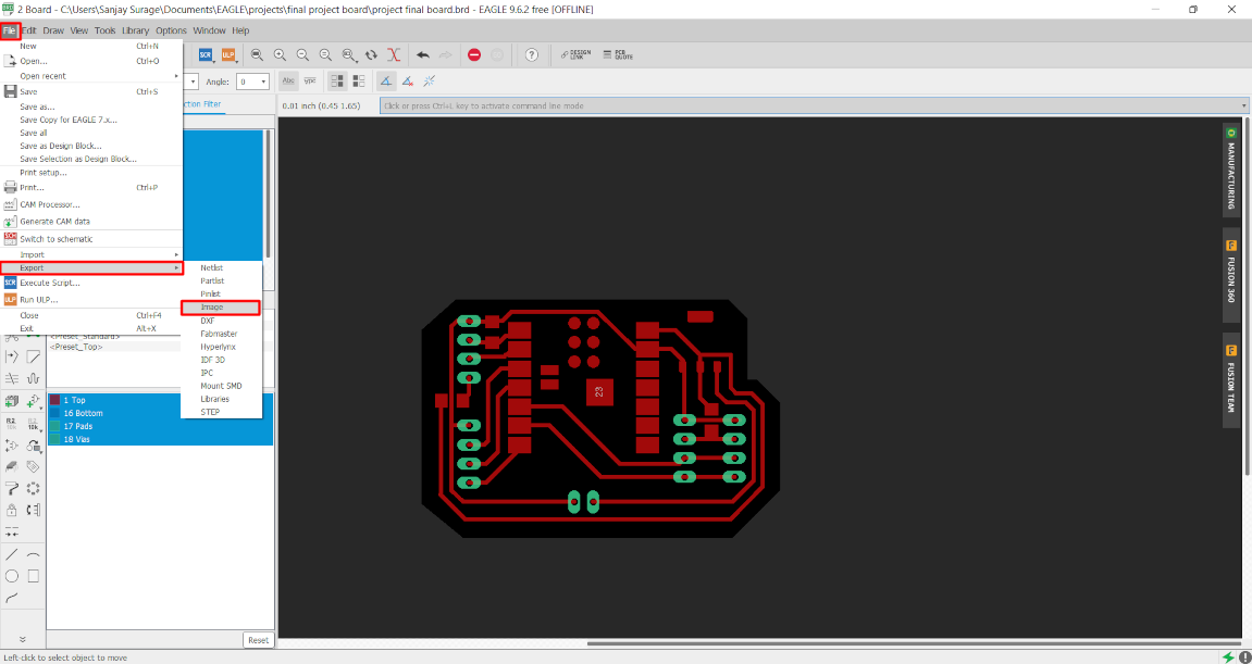
After that go to the file option and select export. and in export option select image and click on ok.
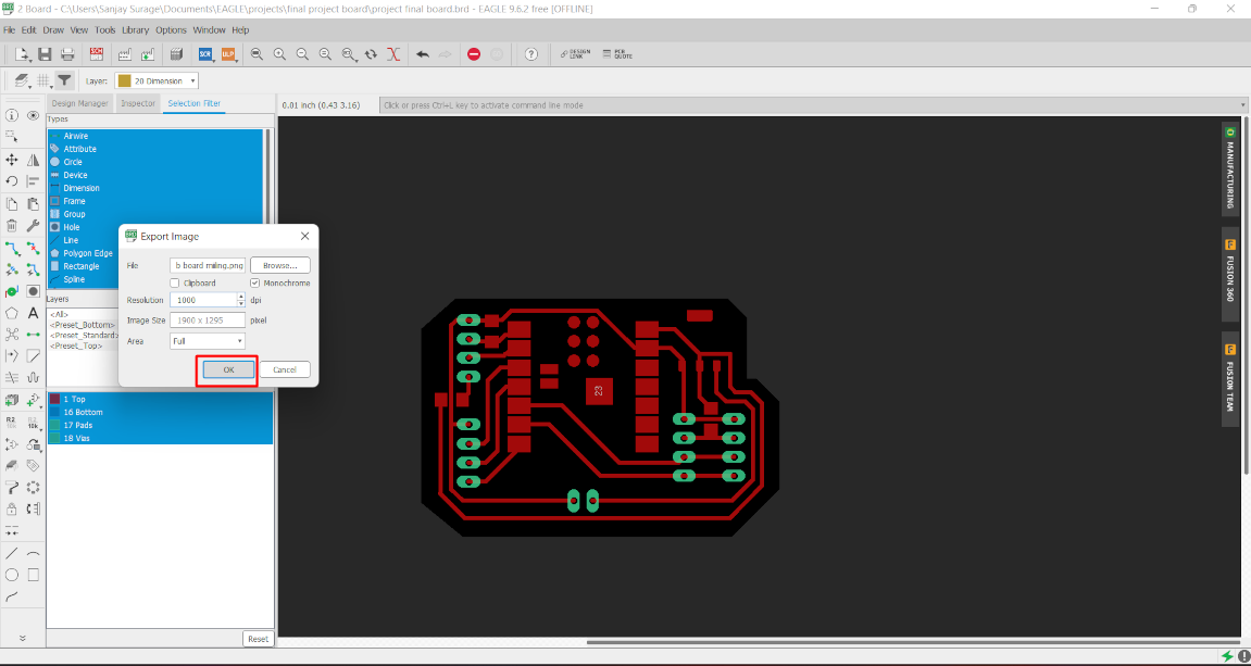
Then a new small window open. Here browse the location where we want to save the file, select monochrome option and make resolution 1000 to better milling operation and ok.
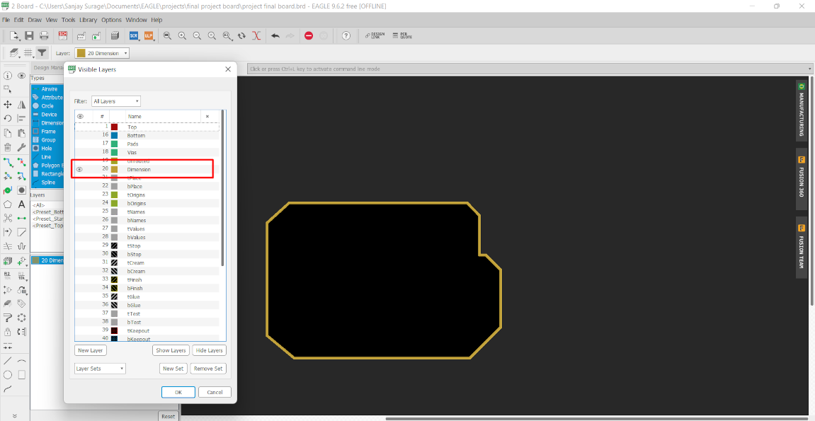
Similarly do this for dimension layer. Go the layer option again and hide the all layer then select dimension layer and press ok. Then follow the same process for dimension layer as we follow for the milling process.
Png file of the pcb are given below.<>
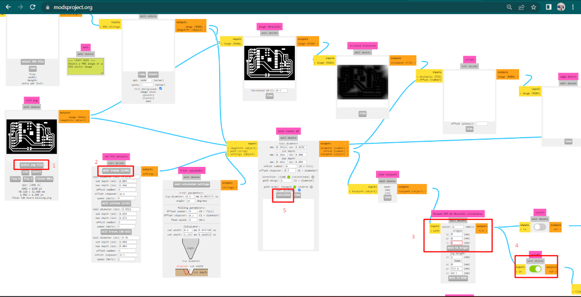
Toolpath Generating
There is a many software by which we can generate the toolpath for the pcb milling machine. Now we are using MODS CE platform to generate toolpath.
This platform is manage by MIT-USA. By this platform we can cotrol our machine also. It create toolpath for many machines like shopbot, vinyle cutter etc.
Search the mods ce on Internet and open it . A blank window is open Then right click on the window and select program.
After this open a new program.
Here we find out our machine and enter. Now a window open which contain colorful boxes.Each box is connected with another box. All the box contain some values.
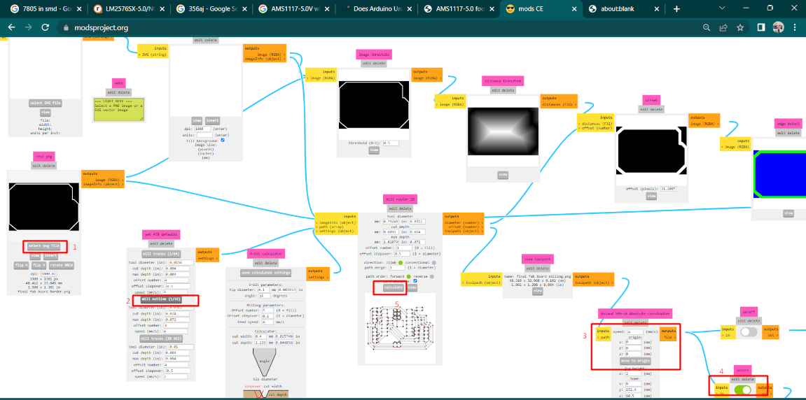
So firstly I upload the tracess milling file and then select 1/64 tool . After that I enable the save option and make XY and Z axis as zero. Then we clcik on calculation. After that A .rml file is downloaded for the machine opertaion.
After Milling we have to generate toolpath for the border cutting. all the process are same. we have do changes in tool selection option this time . Select the 1/32 tool for the cutting operation.
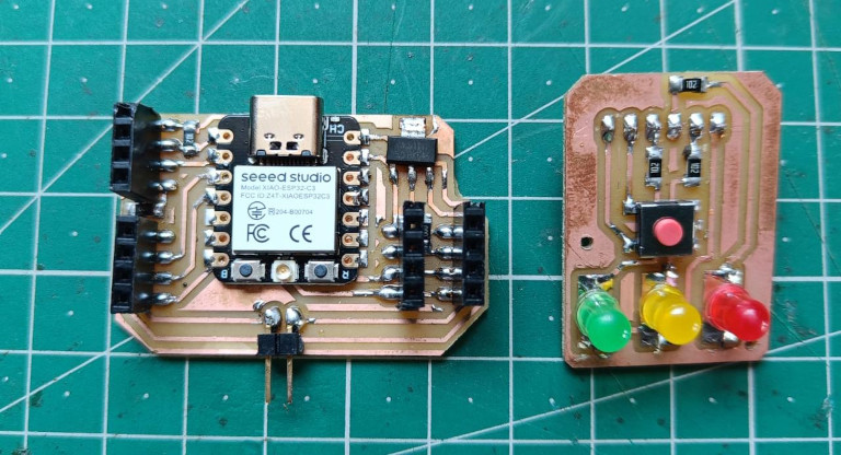
Now for controlling I design a Another pcb which carry the LEDs and push button switch to change the mode.
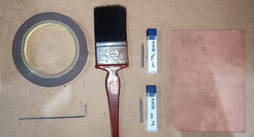
Machinig process
Now in machining process we milling and cutting our PCB board. before machining lets ready the initial arrangment.
Things we need in machining process-
1.Copper clad Board
2.Milling and cuuting Tool
3.Alen key
4.Double sided adhesive tape
5.vaccum cleaner
6.Brush
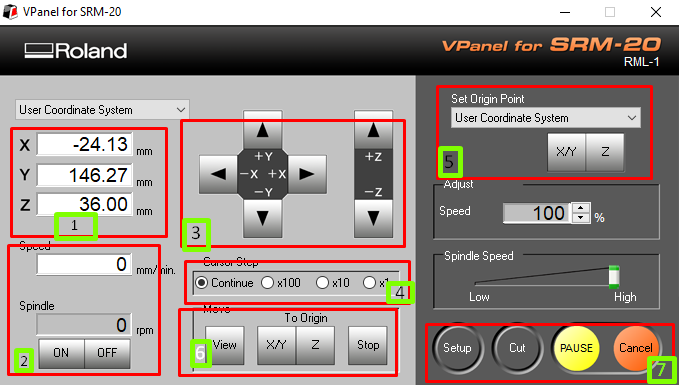
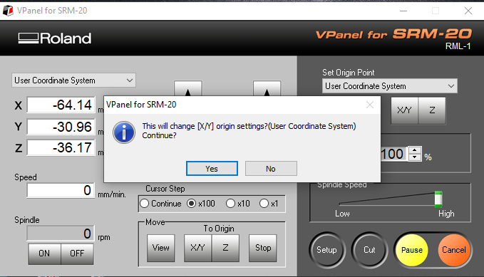
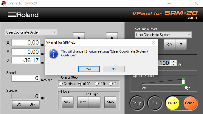
firstly powen on the machine and open the V panel software of the machine. when machine is power off the v panel cant be open .
Now In software there are x, y and z axis controller are there. At the down side we set our machine tool on origin. and its cursor speed can be controlled by the
parameter. At the right side we can set a new origin point for the tool head and the down side we have some controlling option.
Box1 show the axis values
Box 2 at the down side we can see the feed speed and spindle speed of the machine.
Box3-from here we can move all the three axis
Box4- From here we can decrese our cursor speed
Box5-here we set the the current values of X, Y and Z axis as origin.
Box6-this is used for the movement of axis toward the origin.
Box7-this is used for machine control at the time of operating. also it have cut option by which we select the rml file for milling and cutting.
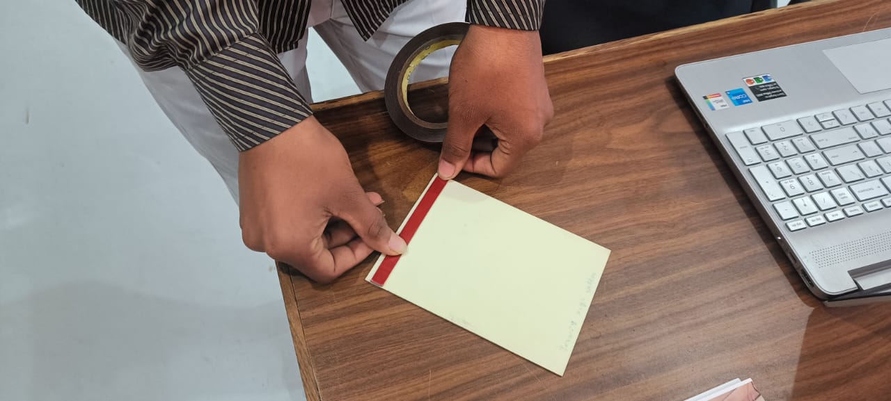
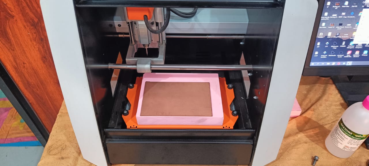
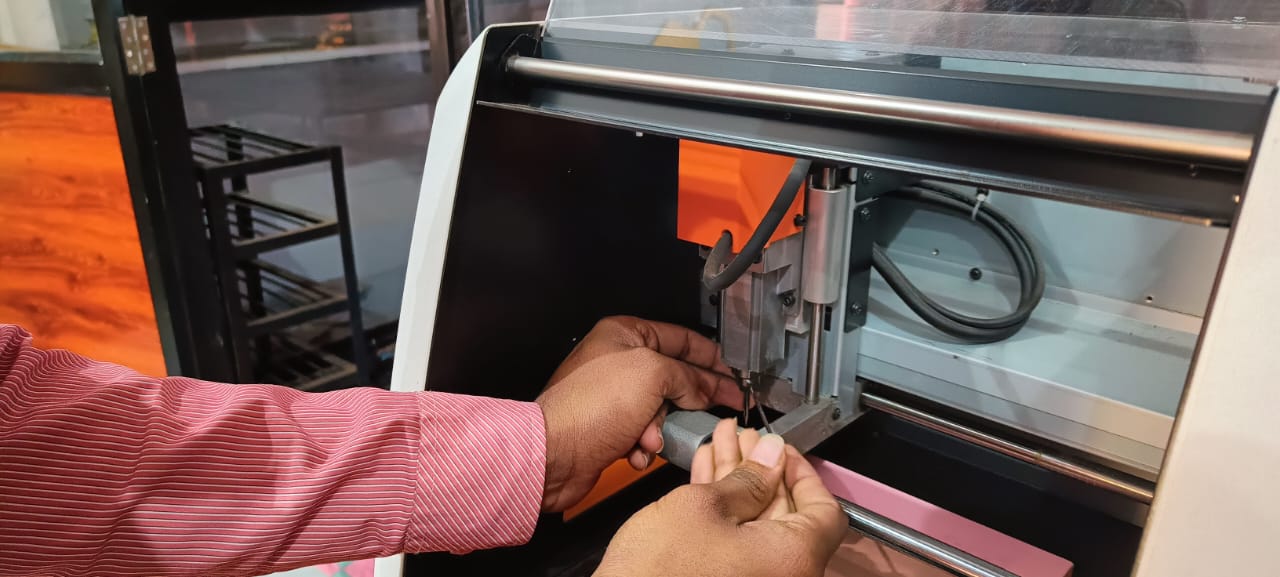
Now firstly apply the double tape on the copper board and stick them on to the machine bed. Then select 1/32 milling tool and tight it on the tool head.
now select a origin point on the basis of x and y axis dont set z as origin. after selecting x and y axis as origin now slowly down the z axis and stop when the gap between board and tool
is just about 3-5 mm. Now loose the tool, it freely fall on the board then tight it agian, this is known as gravity test by which tool is perfectly come in contact with
copper board. Now select z axis as origin.
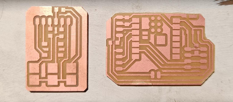
After the machining process my both PCB is ready.
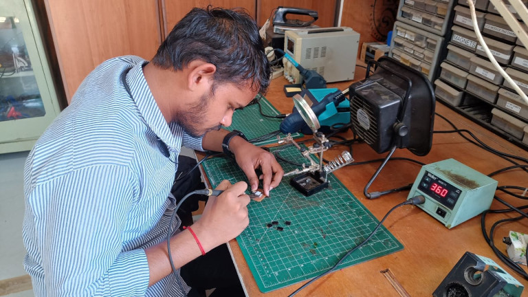
Component Soldering
we used soldering wire which is made up of solder and it is alloy of lead and tin. Soldering wire has low melting point that why we used in our component soldering.
This wire also have a flux core inside it. flux help in increse the wetting ability of solder wire by which it can spread rather than making a round ball.
STEP 3 : PCB AND COMPONENT TESTING
After the soldering process my PCBs is ready to test with other current sensor, oled display and DC motor. I connected all this component . I supplied the power to the motor by the power supply and The power supplied to microcontroller by my laptop.
After arranging them I Programme my Microcontroller. So I given two a condition of 100mA and 150mA. I set the 100 mA for the Tomato Sauce and 150mA for the Sugar syrup. When the motor reaches this value display show ready messag and green led turn on.
STEP 4 : FABRICATION AND ASSEMBLY
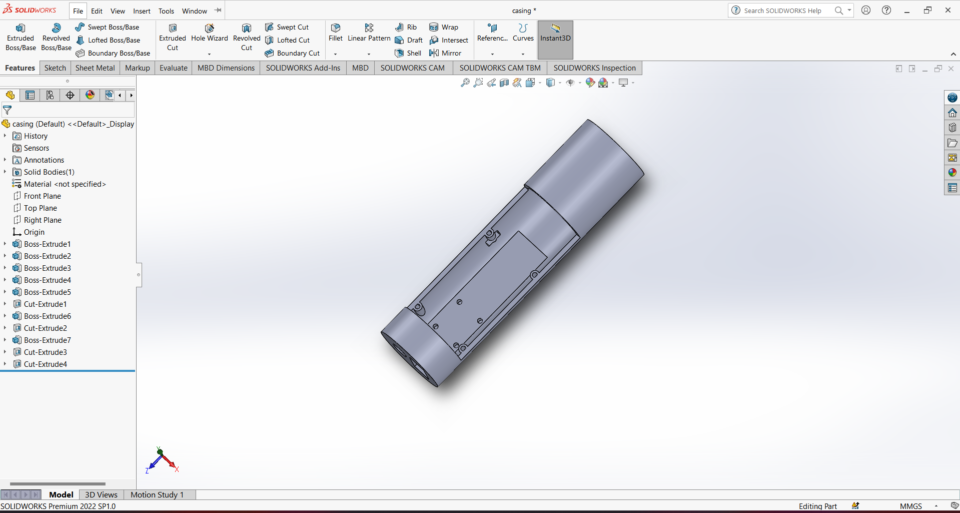
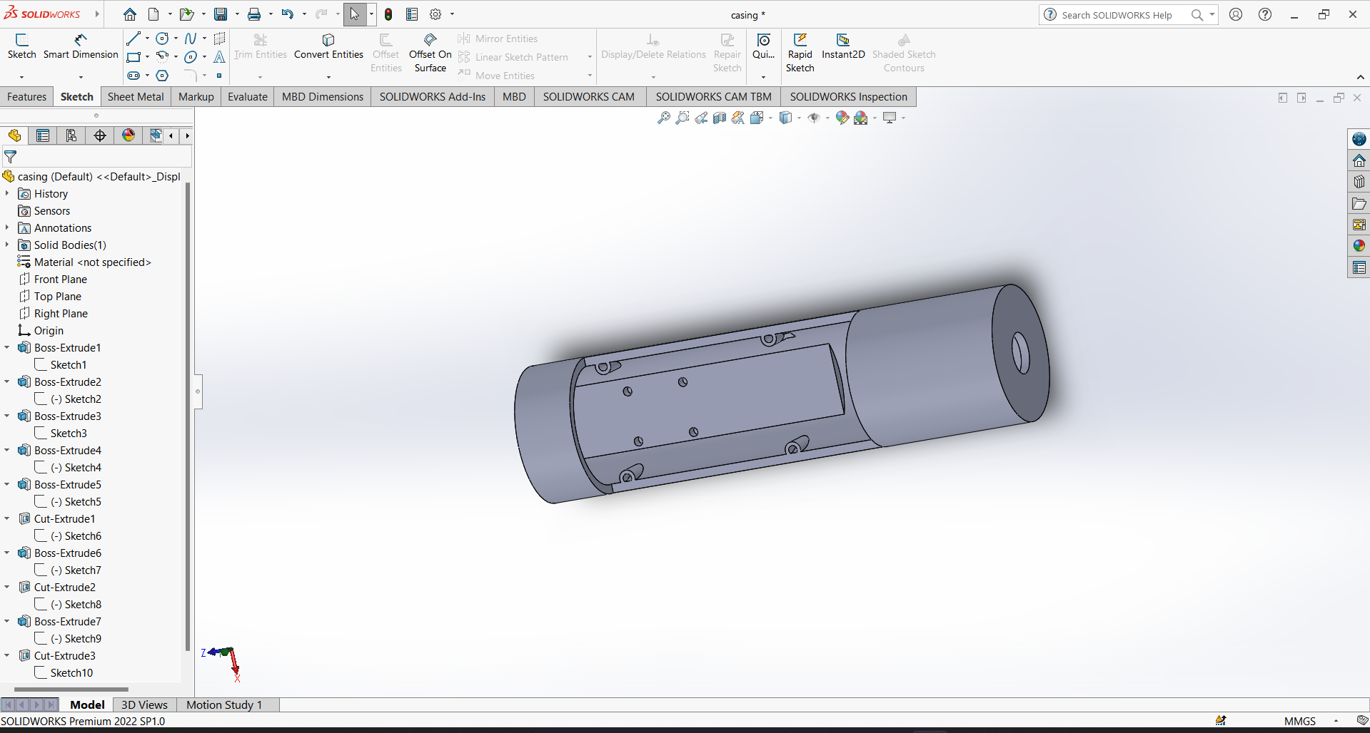
Afte the Testing process I started the design of casing on 3D printer. for design I am gonna use Solidworks software . So I decided to make a round shape for handy use.
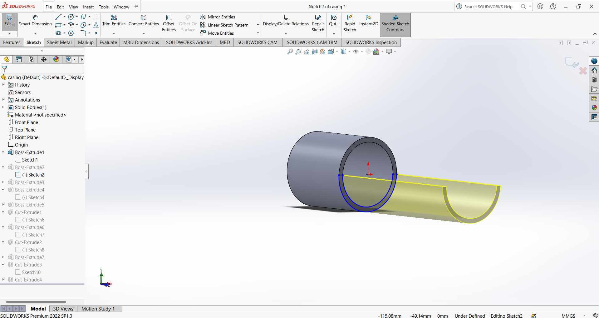
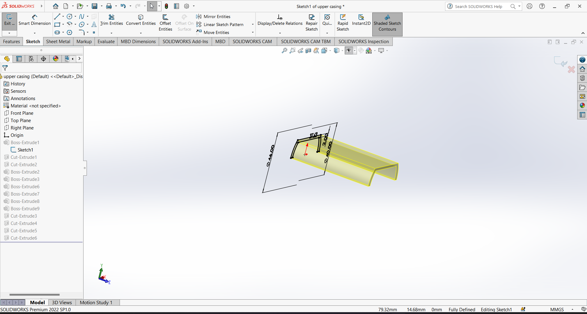
So also decided to make casing in two parts. So I started working on first part. Firstly I make circular cylindrical design for motor then I extended its half part.
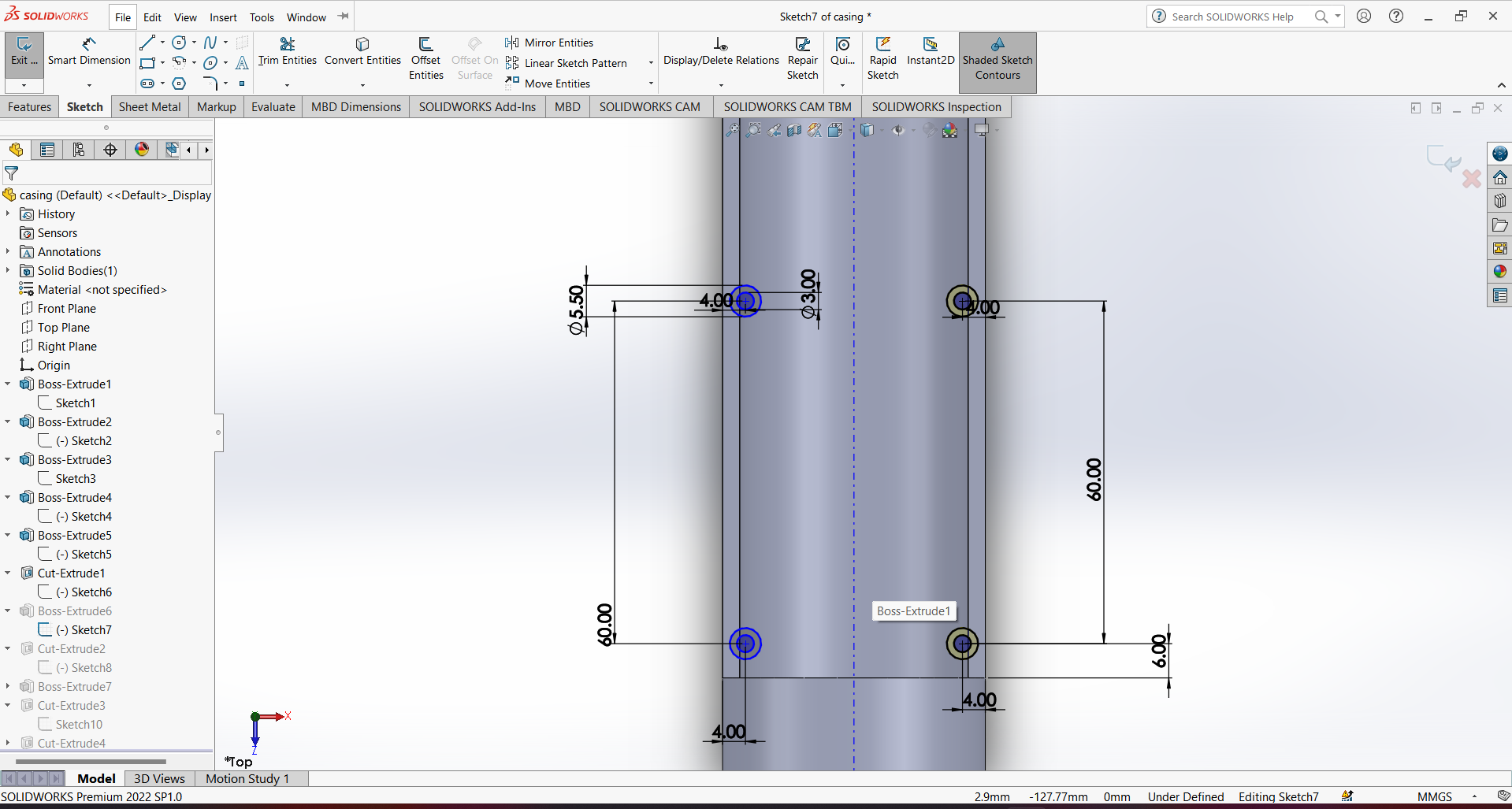
After this At second end I give the holes for the 12v Female pluf and a switch.
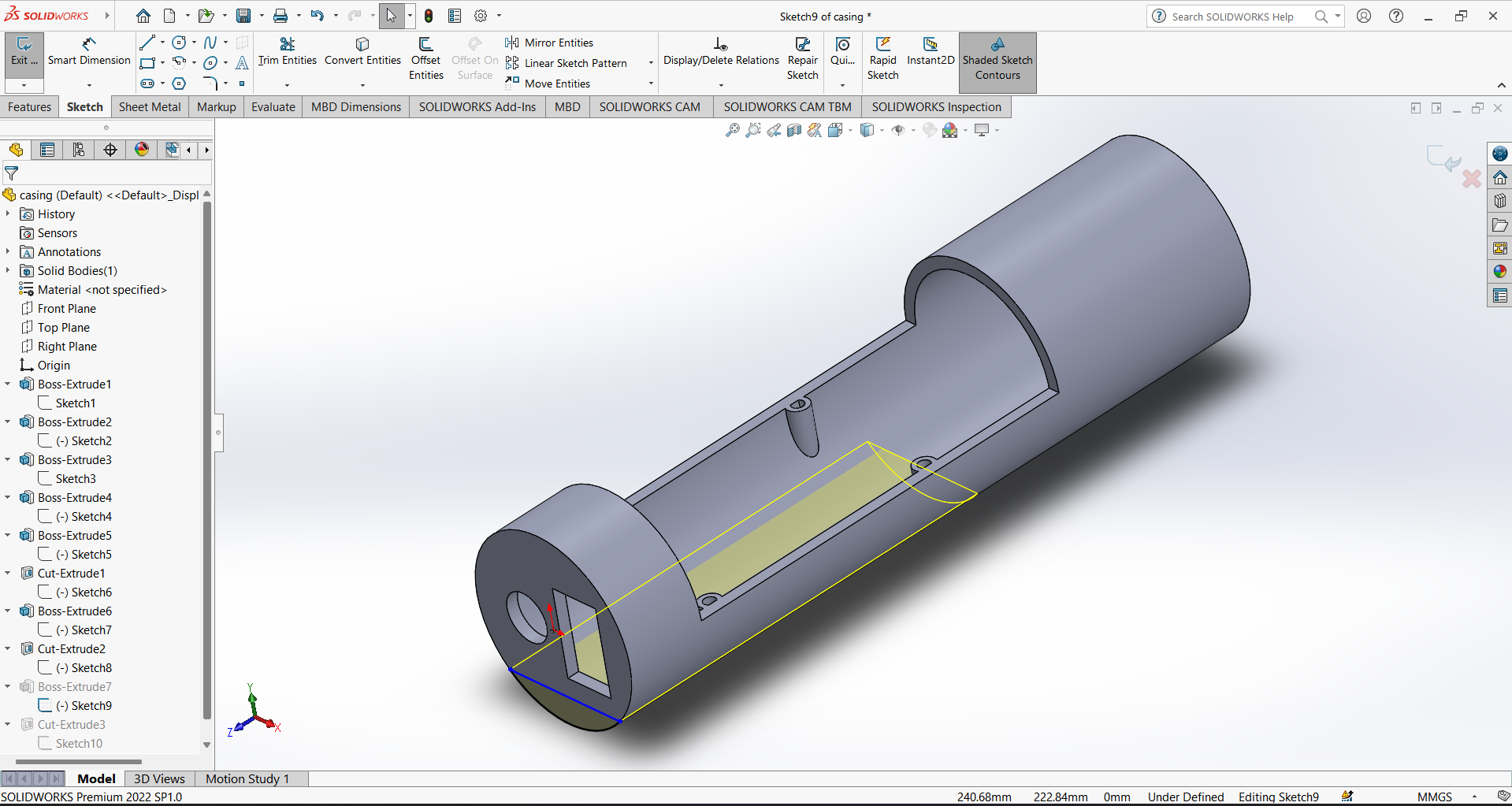
Then I designed the holes for the screw to connect one part with another. After That I Also give a a cut section From which I can programm my Microcontroller.
After this My one part is ready.
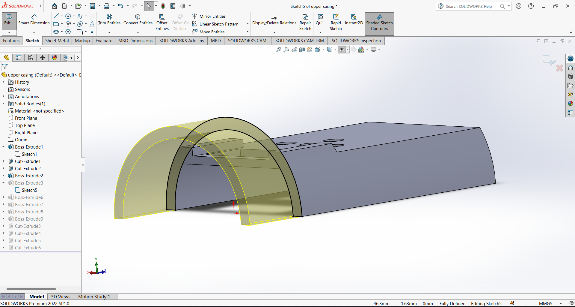
After that i design another part which hold the display and Led and push button.
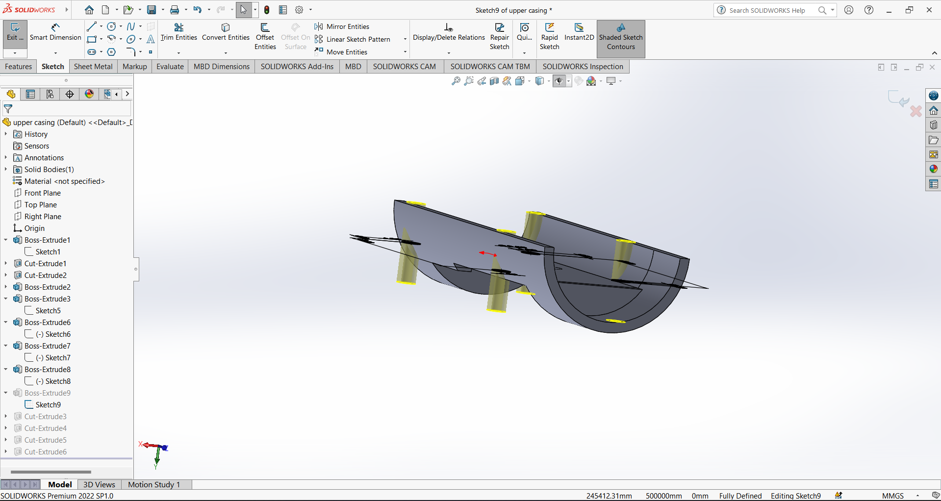
After that at the end of corner I give round shape and also design holes for the screw.
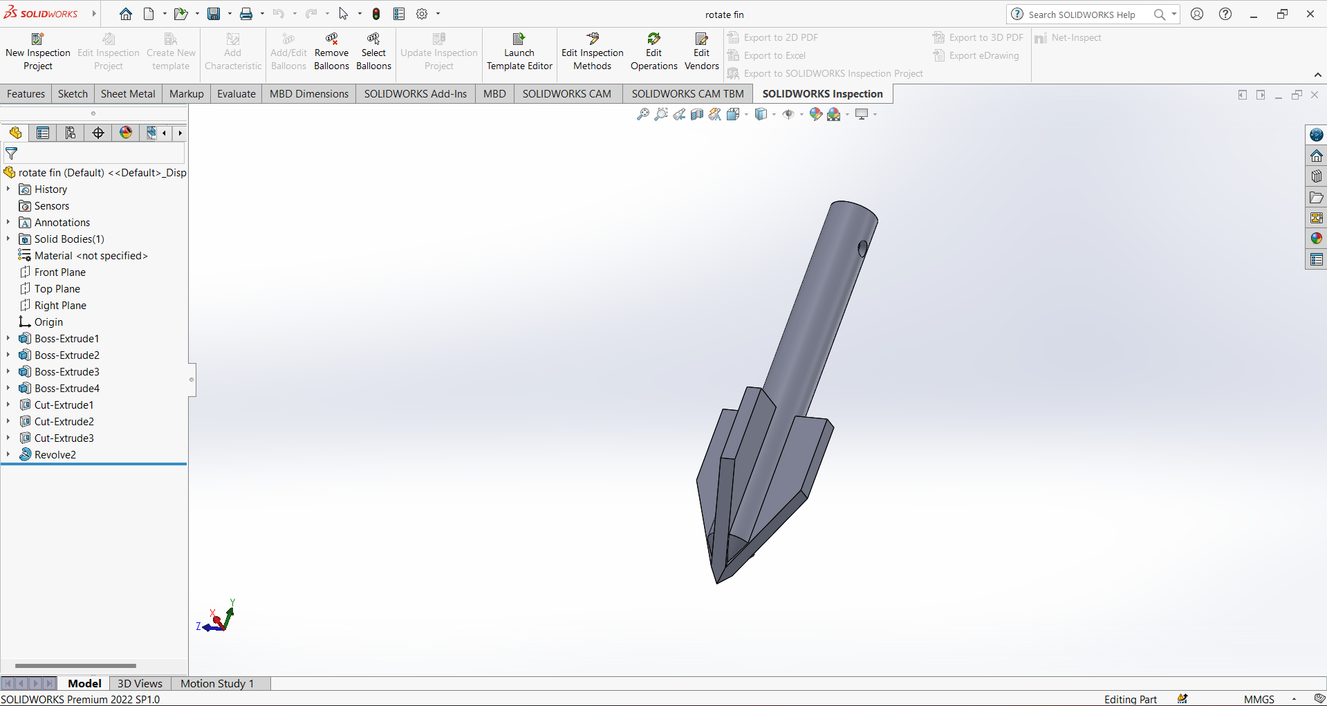
Then I designed rotate fins for the motor shaft. This fins shaft rotate in liquid.
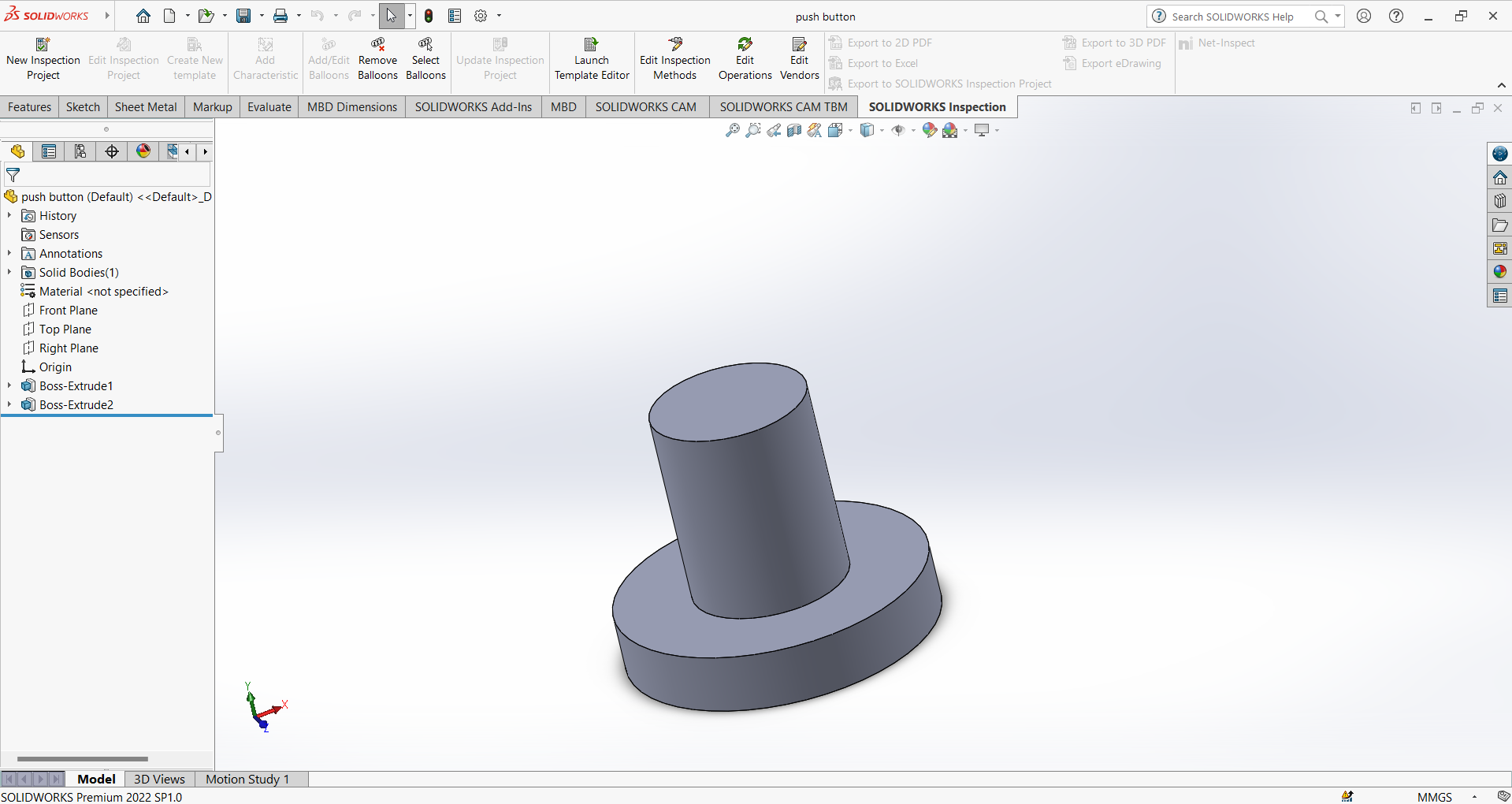
I also designed a pressing button for push button. This pressing Button is set on the push button.
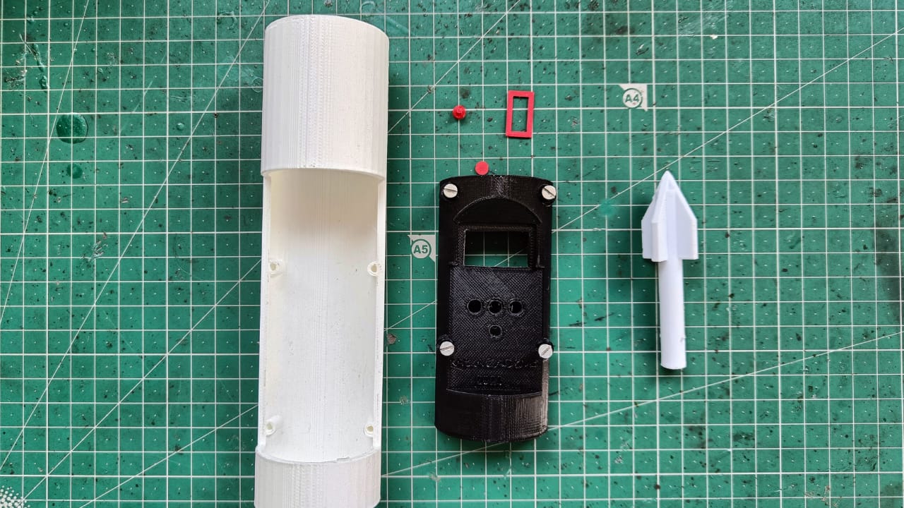
After Designing all the parts I Printed them with the help of 3D printer.
All 3D printed parts shown below.
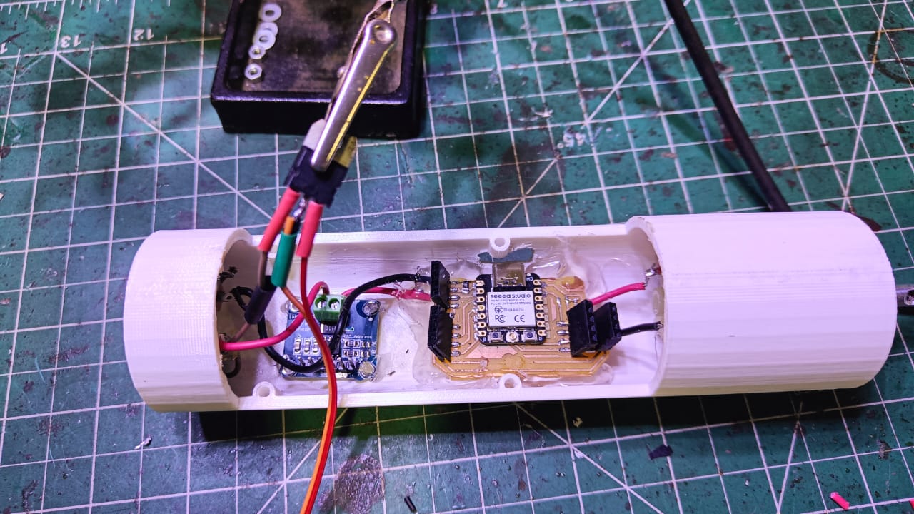
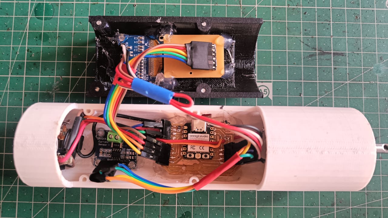
After the part printing I started the assembly process and assemble all the component in proper way.
Assembly Process
I used 7805 voltage regulator and connect it with 12v supplie. It give 5v output and this 5v is supplied to the microcontroller.
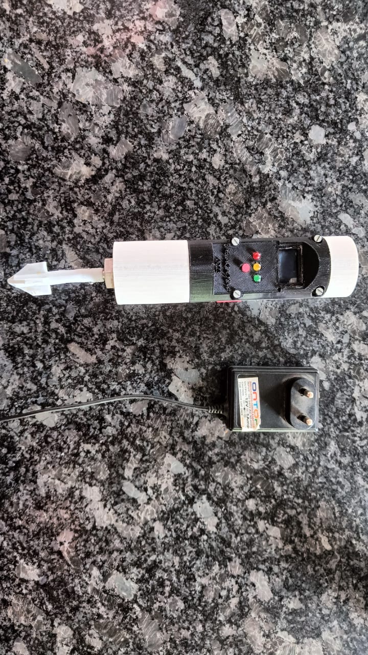
After the final assembly my project look like that.
STEP 5 : CALIBRATION
After the assembly of all the parts. Now I have to calibrate my device with Perfect liquid. Now my device have three mode. So i switched it with third one and measure the live current required for the machine. The value of current required by motor shown on the display. Then I start calibrate it with sugar syrup and we get 56.9 mA.
Then I calibrate it with the Tomoto sauce and get the maximum current of 58mA.
STEP 6 : FINAL TESTING
After The calibration I Finally test it with Tomato sauce and it work fine. Which is shown in my final presentation video.
In future I will use higher accuracy sensor which sense the little difference in current. The design of rotating shaft fins need to be llarger in size to produce high torque on the shaft. By which we can measure the amount of current easily. Currently it run by an adopter but in future I tried to operate it with battery.
Learning Outcomes
-This project taught me lots. I applied all my fabacademy knowlede to build this project.
-The casing of the project is my favourite part. It look professional product.
-All electronic working well and I am not faced any major issue in the electronic.
-Its assembly is also one my favourite part for this project. I neatly connected all the component and they working fine and assembly looks good.
Thanks to All
I would like to thank everyone because of whom I got the opportunity to do this course. I learned many things while staying at Vigyan Ashram Fablab. I thank the director of Vigyan Ashram, Mr. Yogesh Kulkarni sir and my instructor, Mr.Suhas Labade sir, who helped me a lot in doing this course. I would also like to thank my friend Pushkar Sooryavanshi who always helped me during this course. Thanks to professor Niel and all Fabacademy Team for this wonderful course. Thankyou.