Week 16: wildcard week
Week 16: wildcard week
the assignment of this week is to Design and produce something with a digital fabrication process (incorporating computer-aided design and manufacturing) not covered in another assignment, documenting the requirements that your assignment meets, and including everything necessary to reproduce it.
I decided to use plasma cutting for this assignment.
A plasma cutter is a tool that uses an extremely hot ionized gas jet to cut through various metals with precision and ease. Its operation is based on the principle of electrical conductivity, generating an electric arc between the torch electrode and the workpiece. This arc, combined with the gas flow, creates a highly concentrated plasma capable of melting and blowing the metal, allowing for clean and defined cuts.
One of the main advantages of using a plasma cutter is its ability to cut a wide range of materials such as steel, aluminum, copper, and stainless steel. Furthermore, its versatility allows for straight cuts, curved cuts, and even cuts with complex shapes, making it an indispensable tool in the metalworking industry, construction, and other related fields.
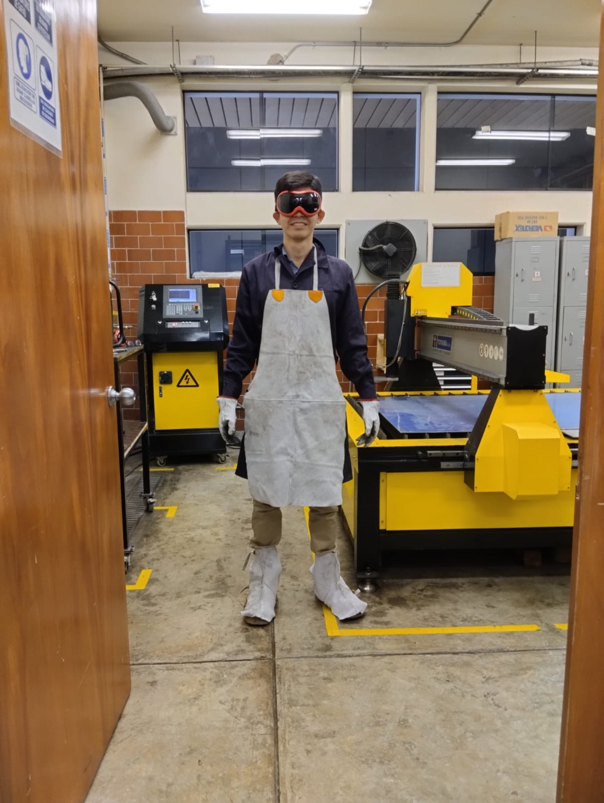
When working with a plasma cutter, it is essential to prioritize safety at all times. To ensure proper protection, it is necessary to use appropriate safety equipment. Here is a list of the recommended safety equipment to use when operating a plasma cutter:
For the design, we used Autodesk Inventor, but this time we created a sheet metal part.
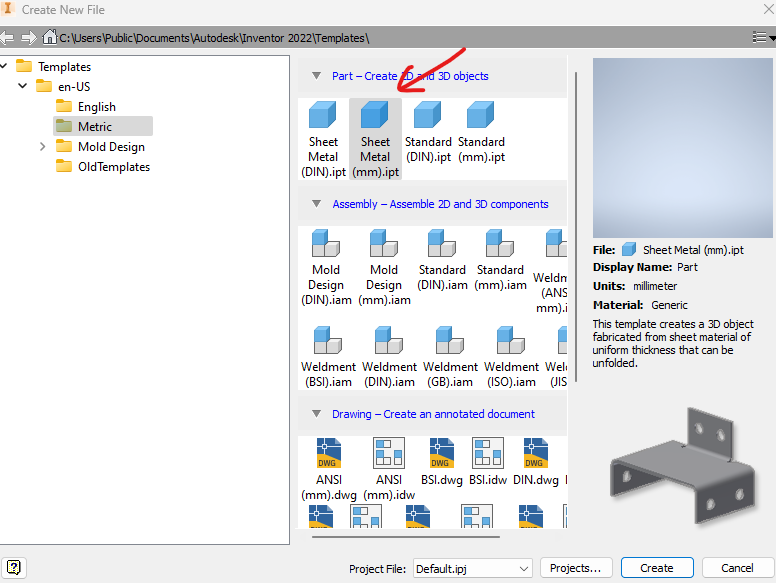
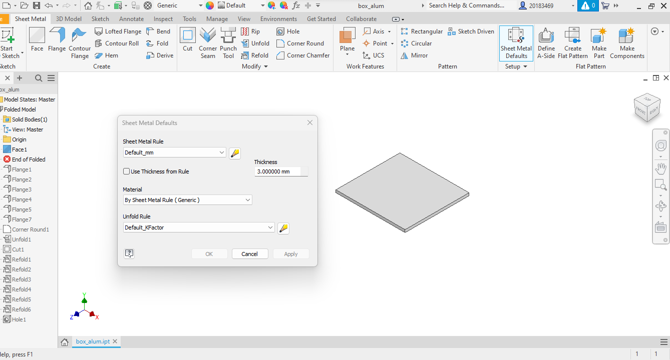
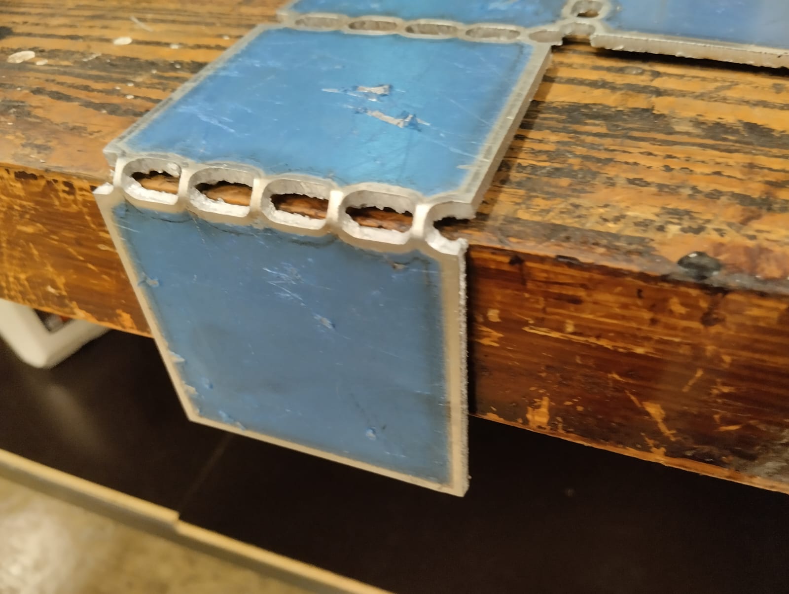
This time, I want to design an aluminum box with a cut pattern in the bending areas that allows the aluminum to be easily folded by hand. First, we will design one face of the box in a sketch, and then using the "FACE" and "Sheet Metal Default" options, we will add a thickness of 3 mm.
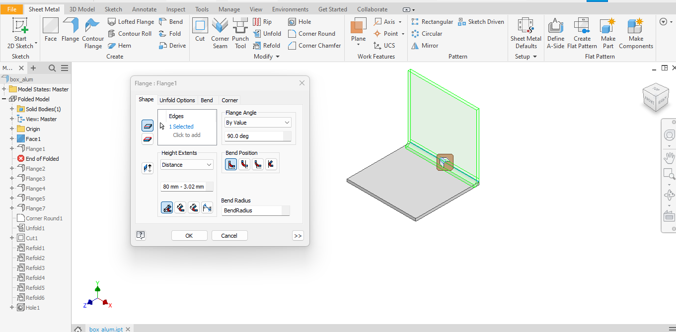
After that, with the "Flange" operation, we can add an extra face and fold it at a 90º angle.
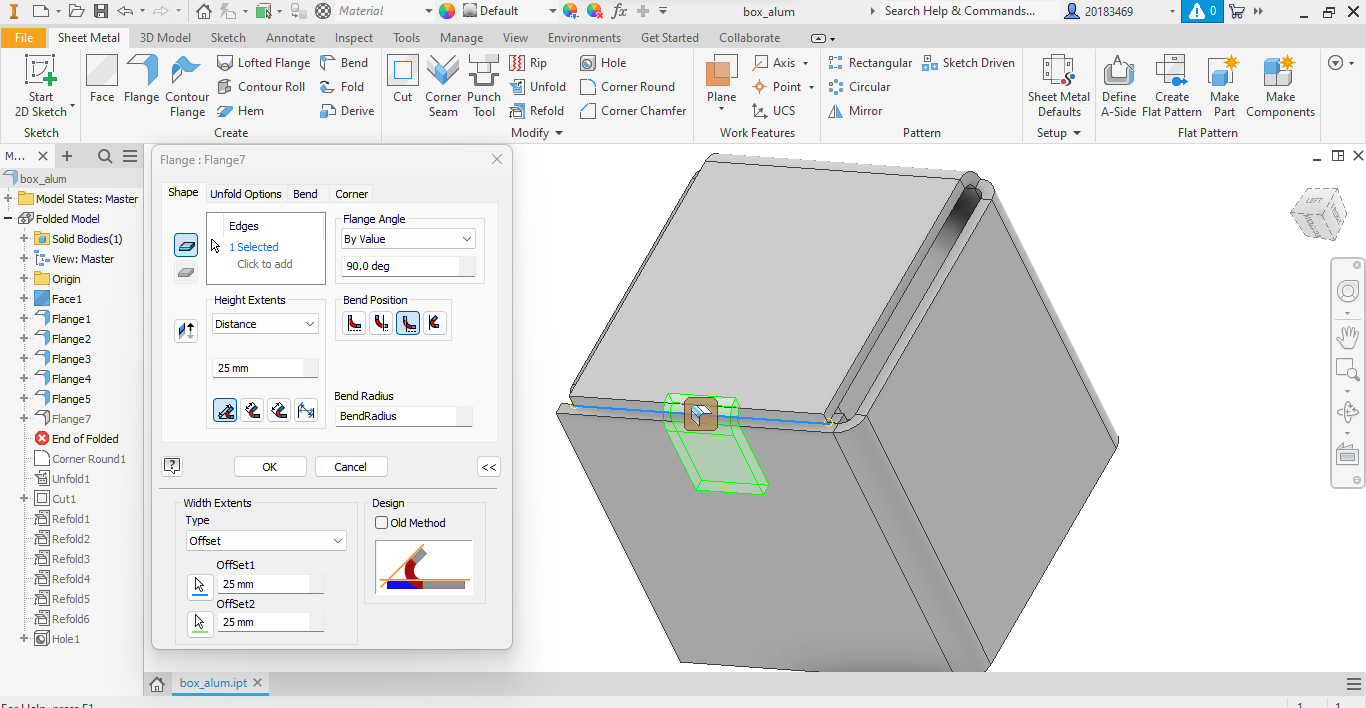
We repeat this process, shaping our box until it is finished.
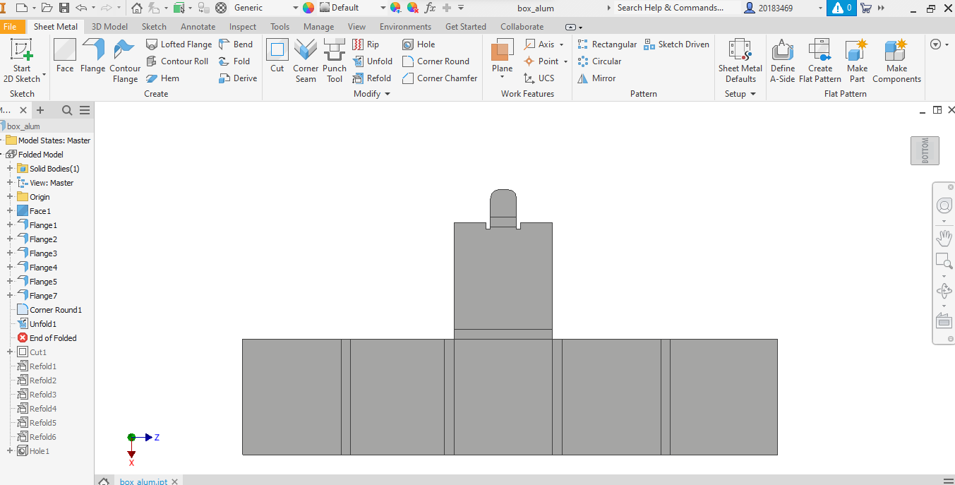
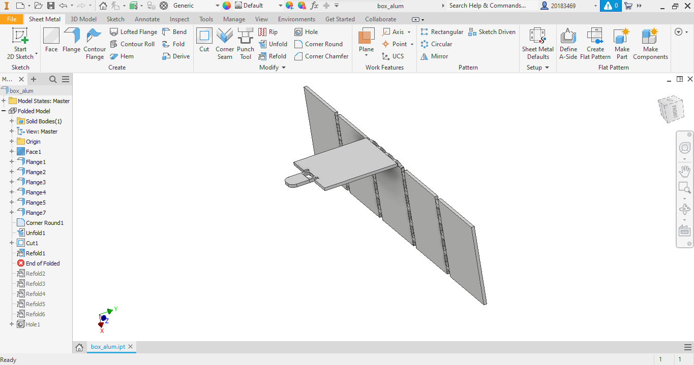
Then we use the "Unfold" option to unfold our box.
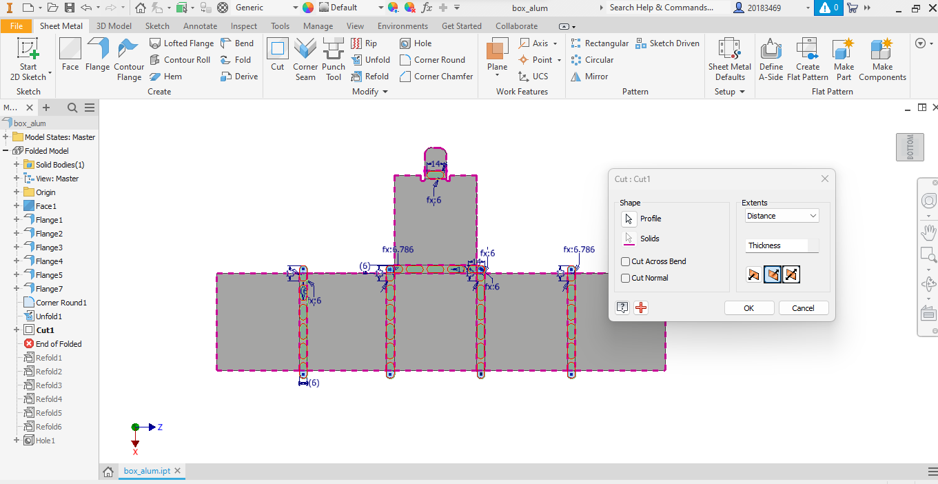
Now, we create a sketch to draw the patterns in the bending areas. Then, using the "Cut" tool, we make the cuts on the solid.
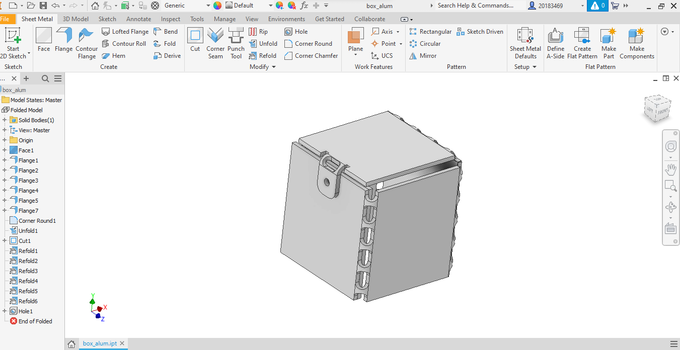
Finally, we can apply "Refold" to reassemble the box.
Here is the final result of the design:
To obtain the DXF file, we need to use the "Create Flat Pattern" option, and then "Export Face As".
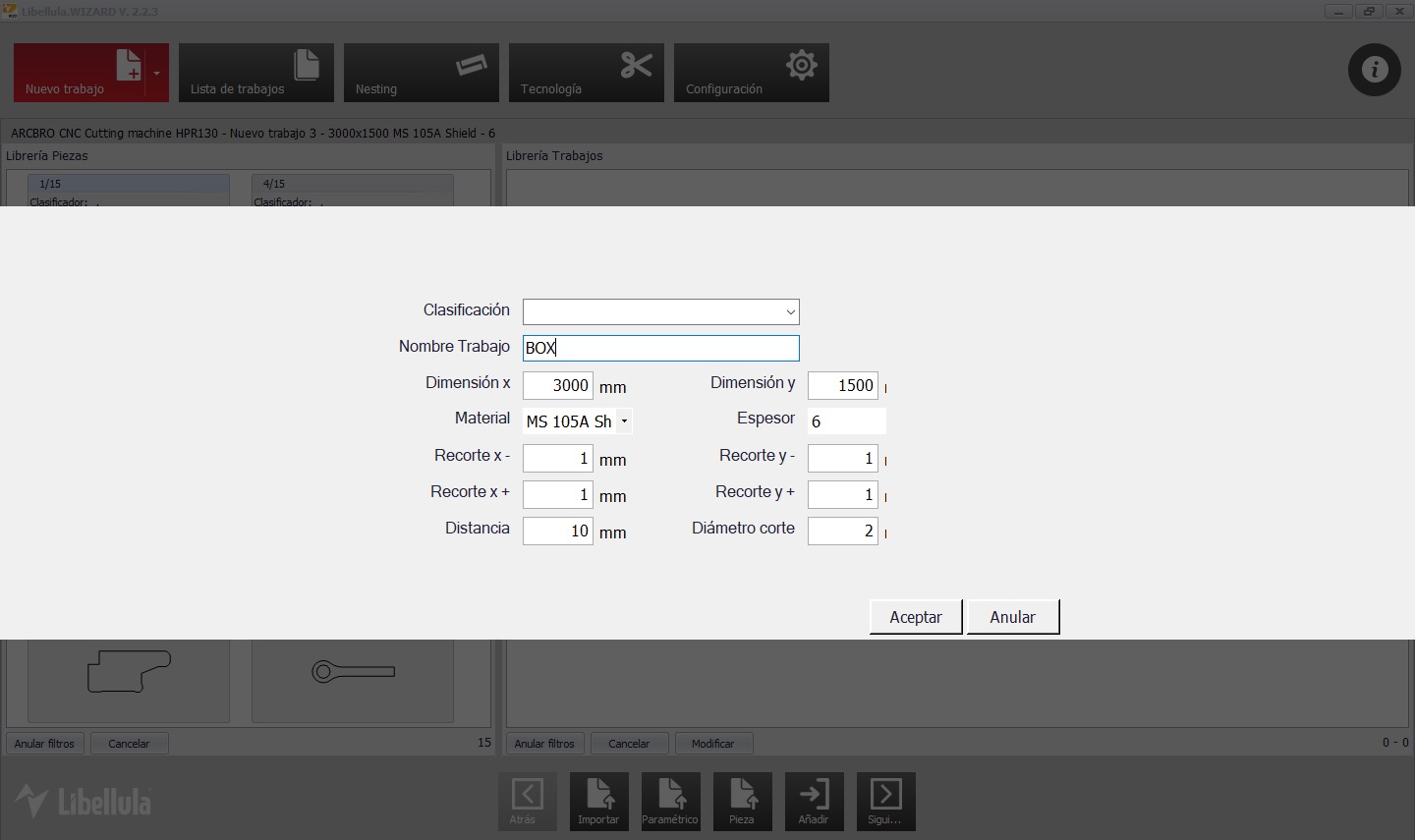
Once we have the DXF file, we can use the software Libellula.WIZARD for CAM (Computer-Aided Manufacturing).
Let's create a new file and give it a name.
To import the DXF file:
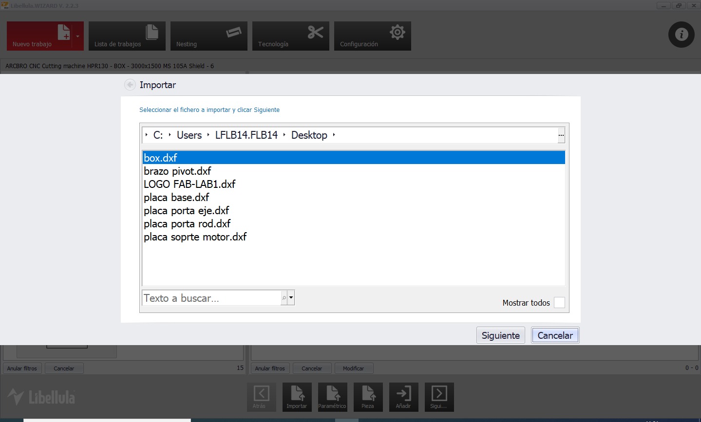
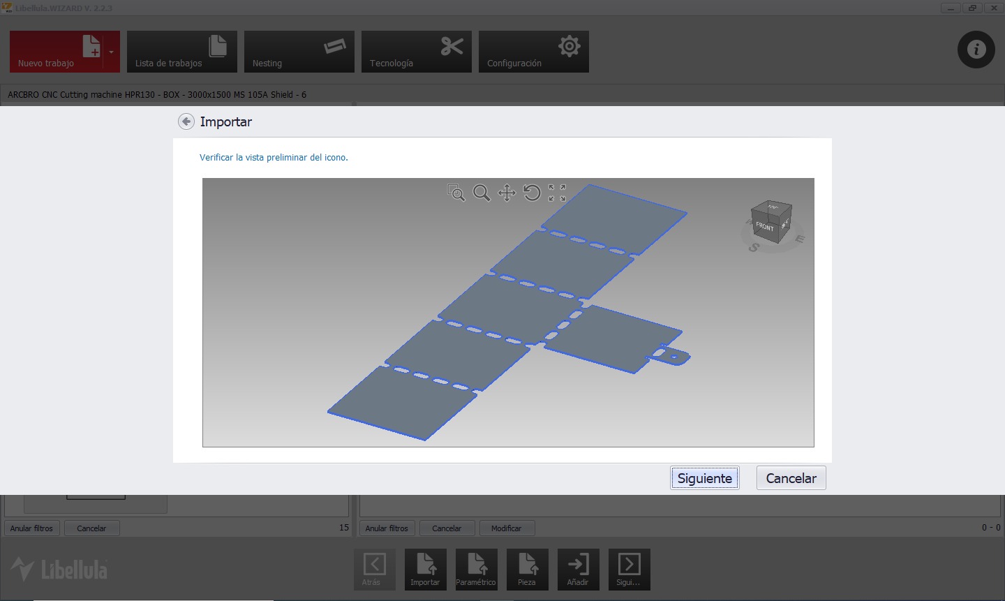
Preview the file:
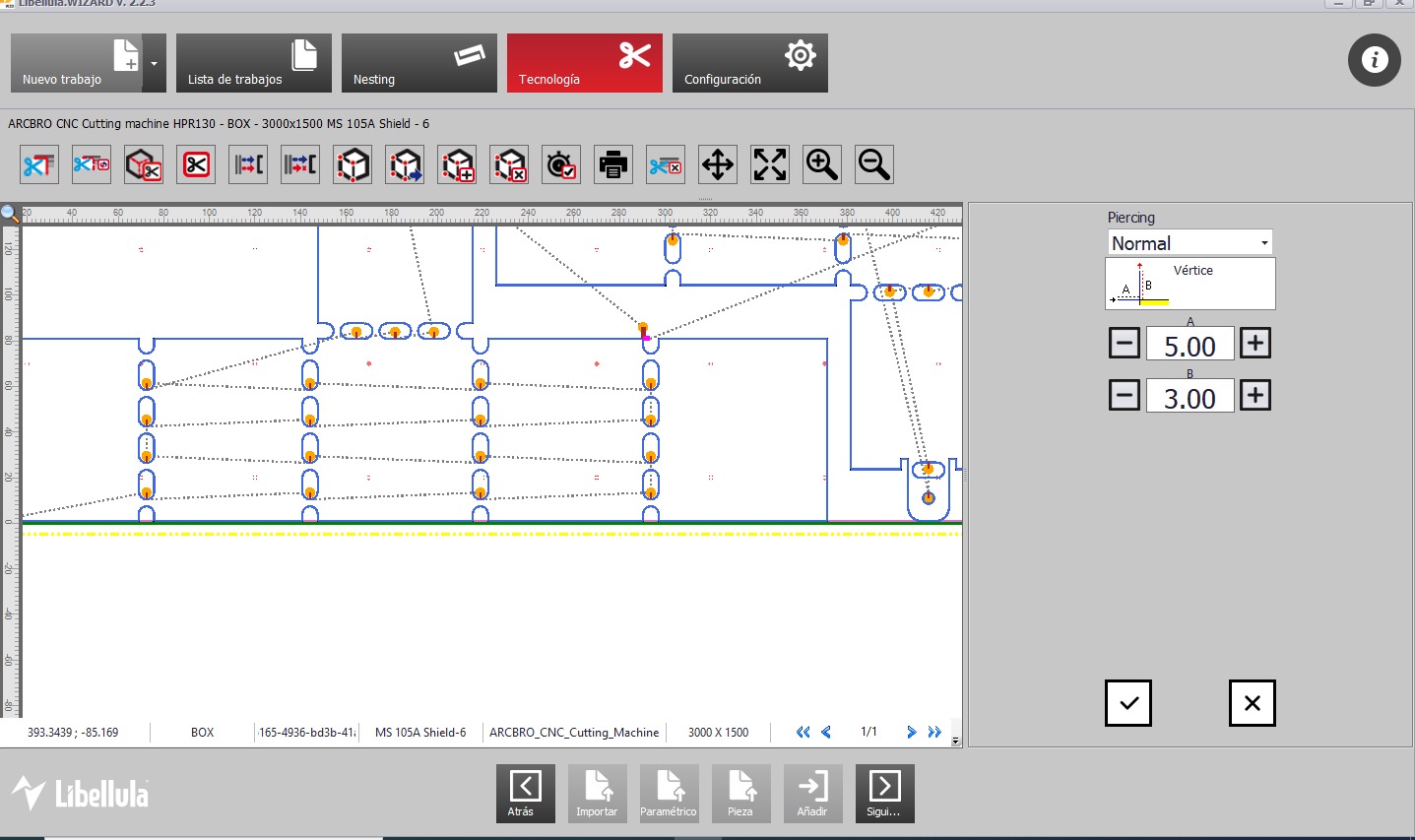
Once the file is imported, we can generate the toolpath that the machine will follow and make some modifications to the toolpath. In the following image, we are modifying the entry length of the plasma cutter nozzle cut:
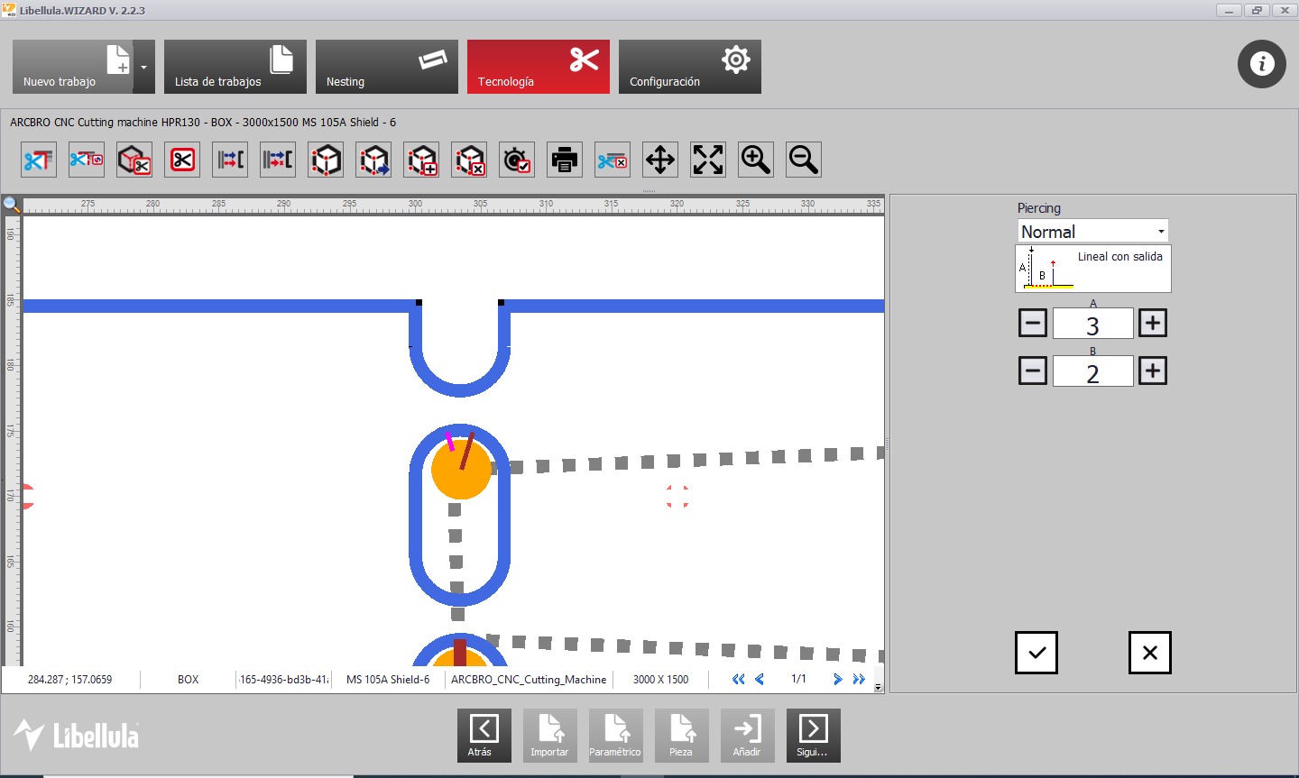
In the following image, we are modifying the toolpath for the holes in the design. We are adding a 3mm offset to ensure that the nozzle covers the entire hole line, preventing any jagged edges that would need to be filed later.
Once we finish modifying these parameters, we press "Next" to generate the G-code.
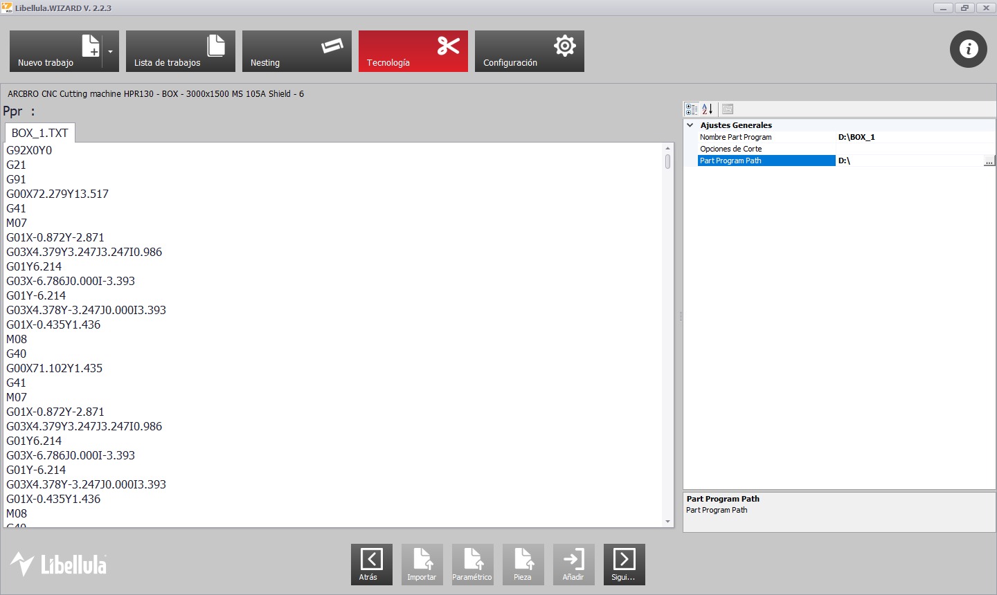
Saved the code to a USB drive, we proceed to the machine for the cutting process.
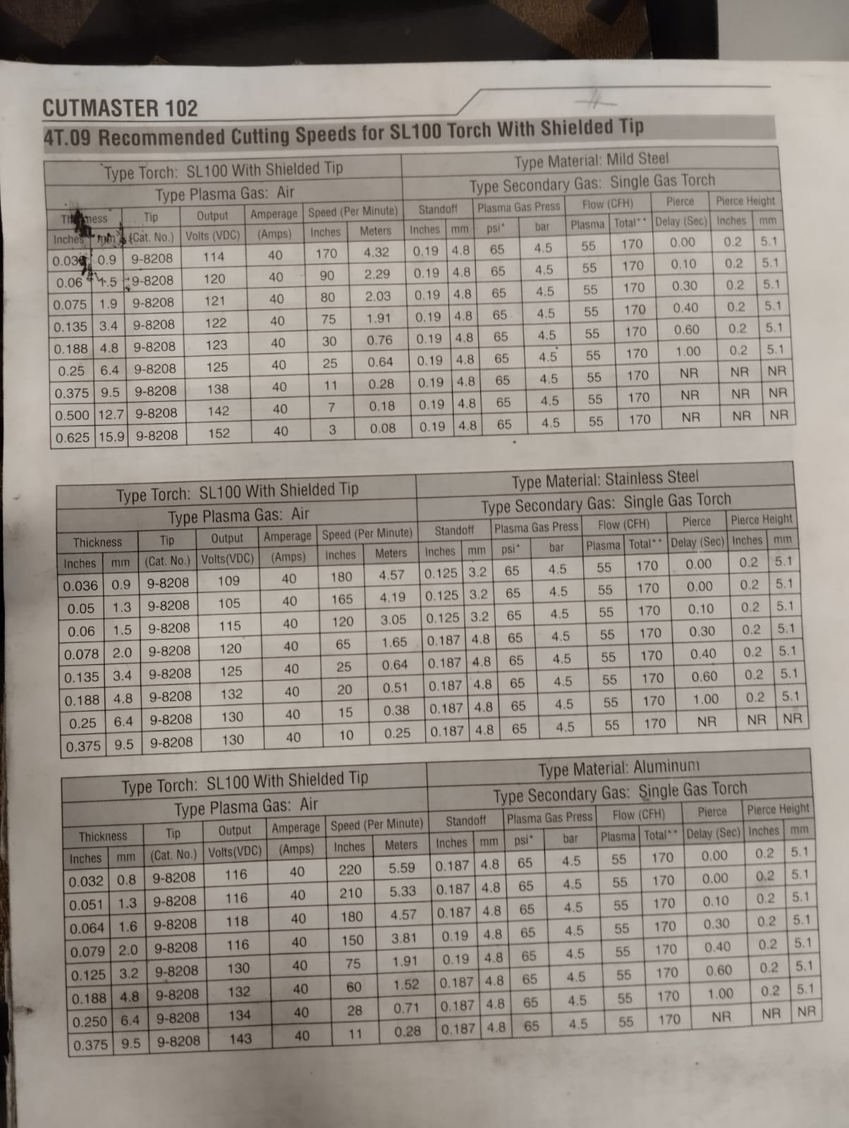
With the generated code, all that is left is to use the plasma cutter to perform the job. First, we select the nozzle that we will use for cutting. To do this, we refer to the table and look for our material and thickness. Since we are cutting 3mm aluminum, we can see in the table that we need 40 amps. We locate the 40-amp nozzle and install it.
Parameter Table:
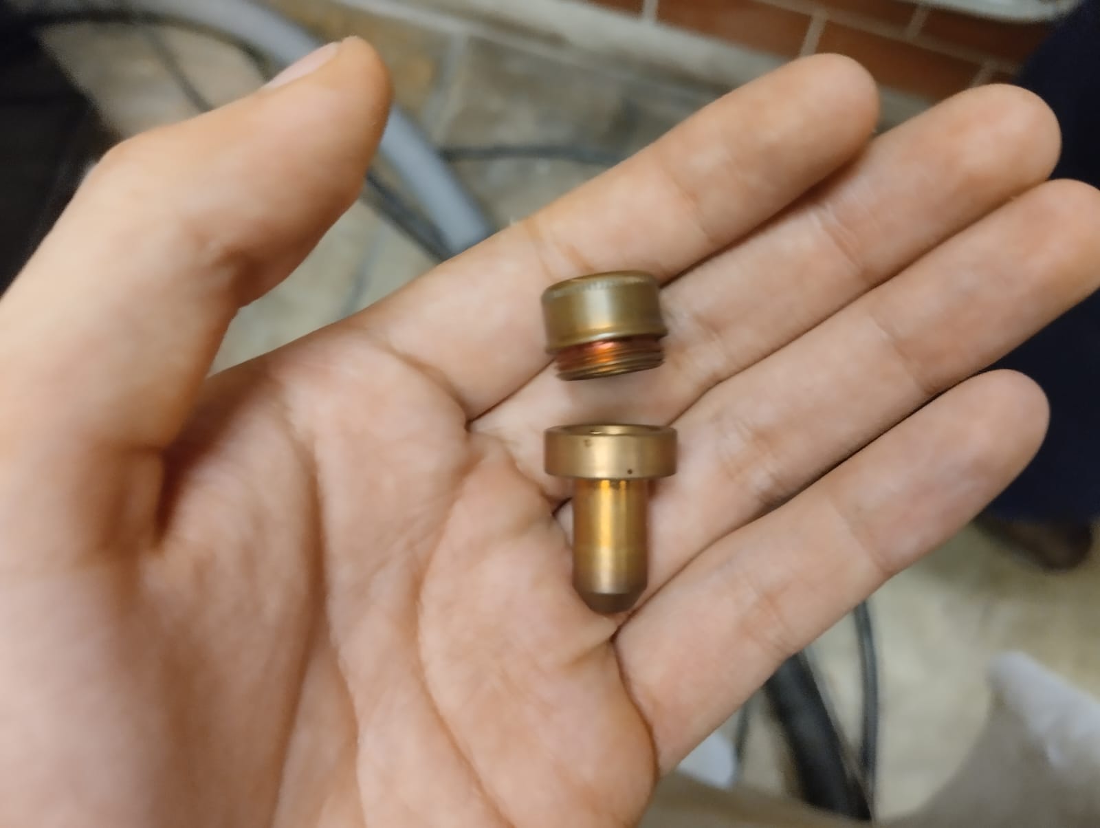
40 A nozzle:
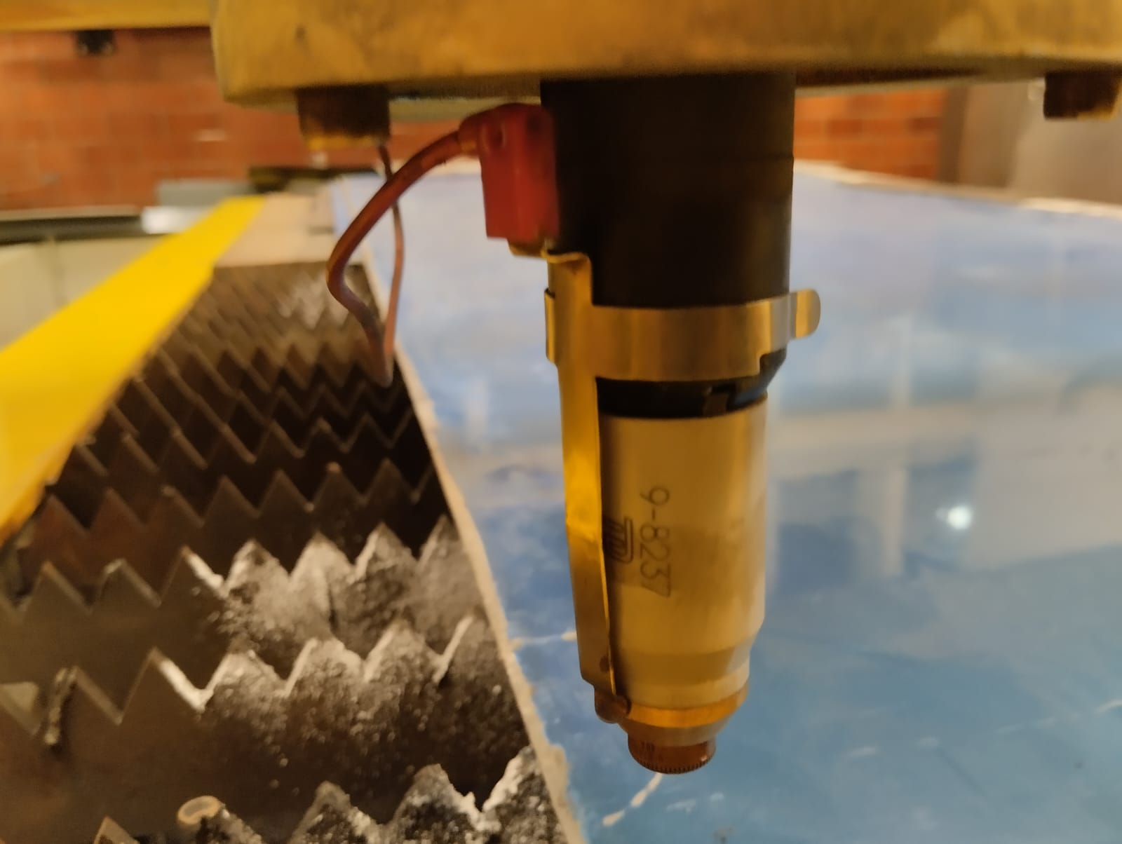
To change the nozzle, we only need to remove the Z-axis sensor and unscrew and remove the current nozzle to replace it with the 40 A nozzle.
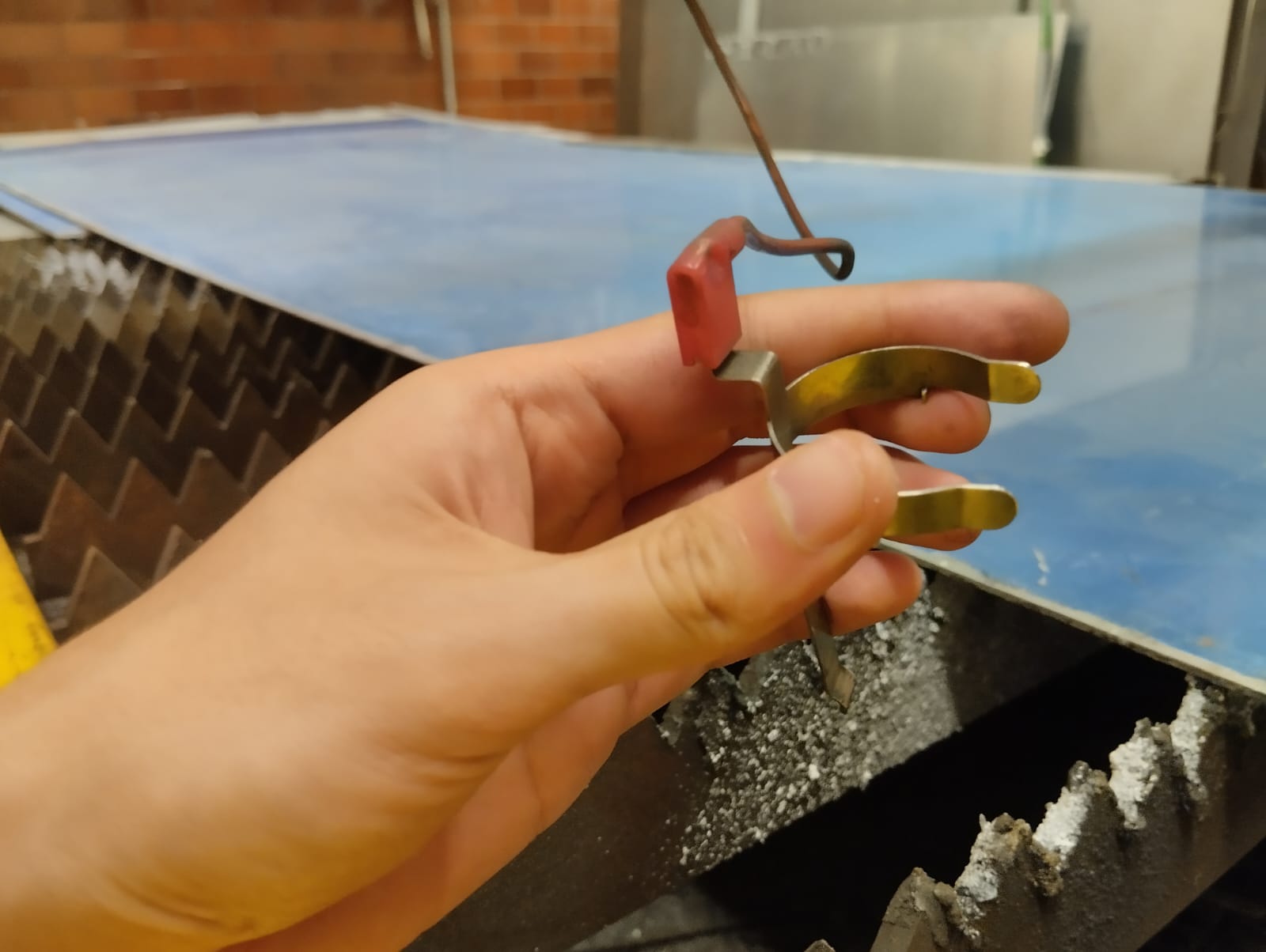
Z-axis sensor:
We screw in the new nozzle and reattach the sensor.
To turn on the machine, follow these three steps:
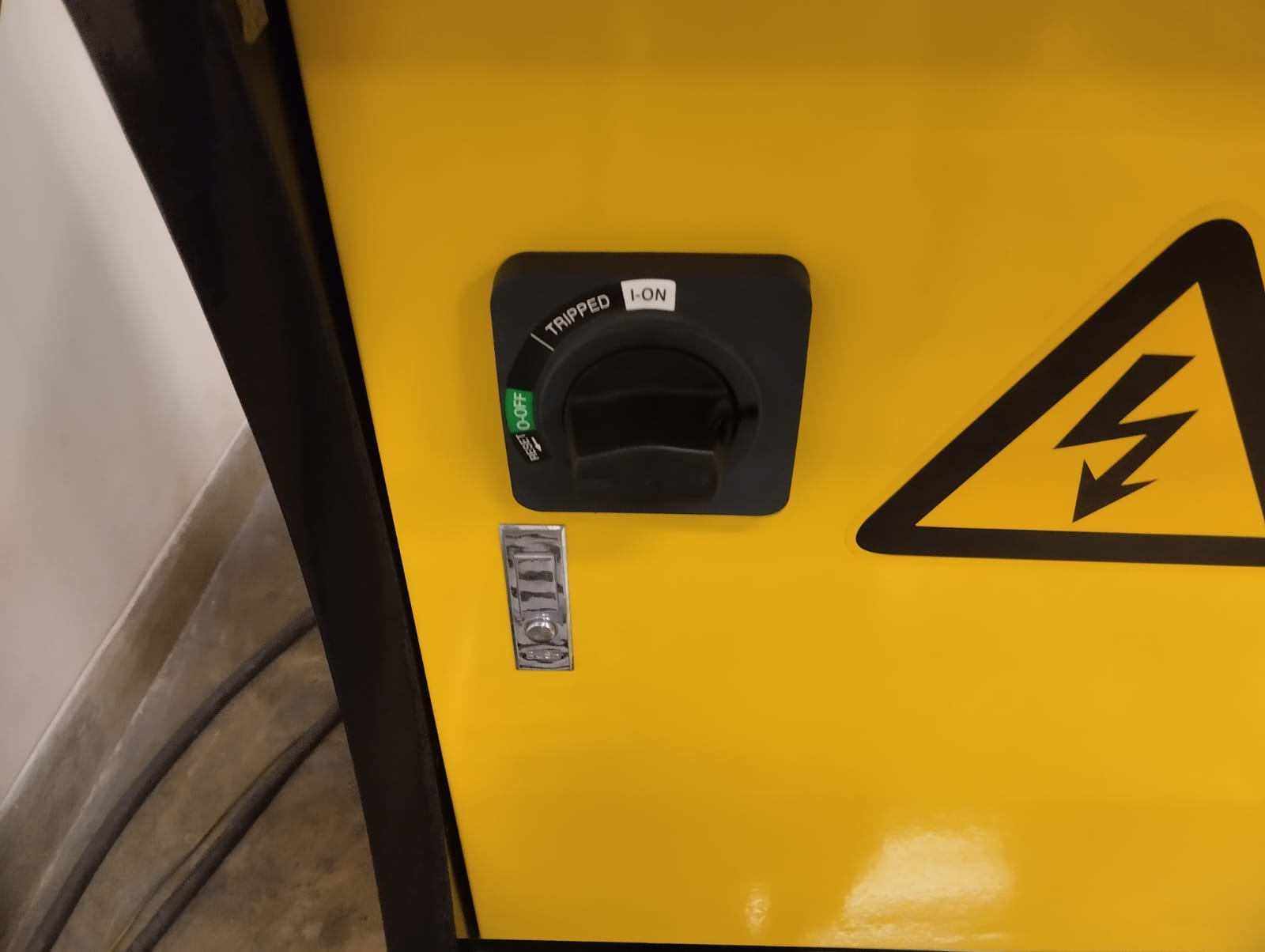
1. turn on:
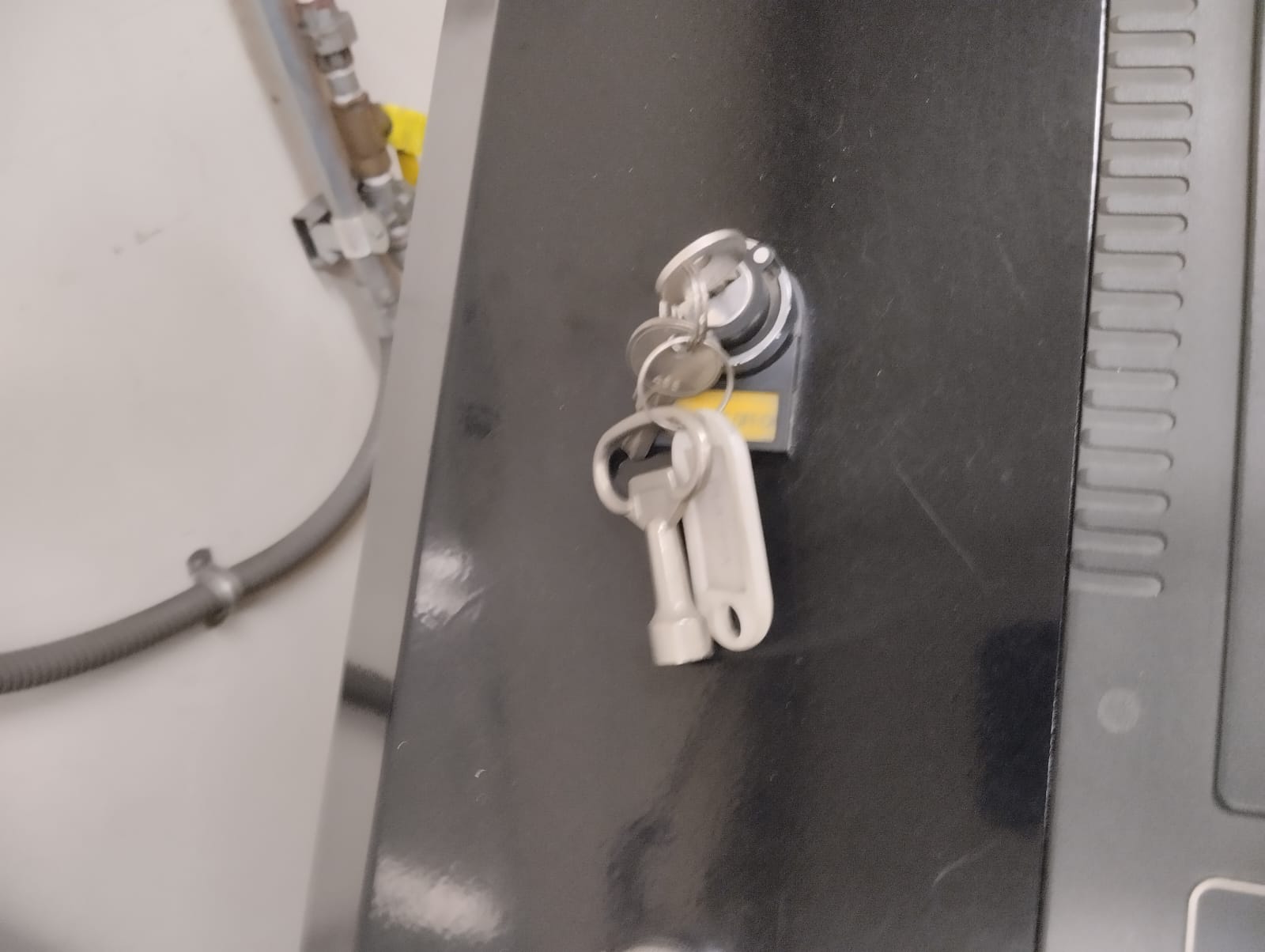
2.Turn the key:
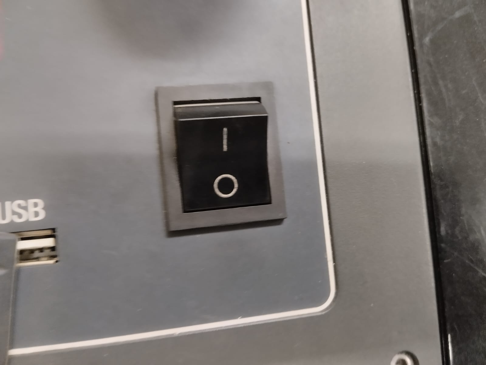
3.Turn on the control panel.
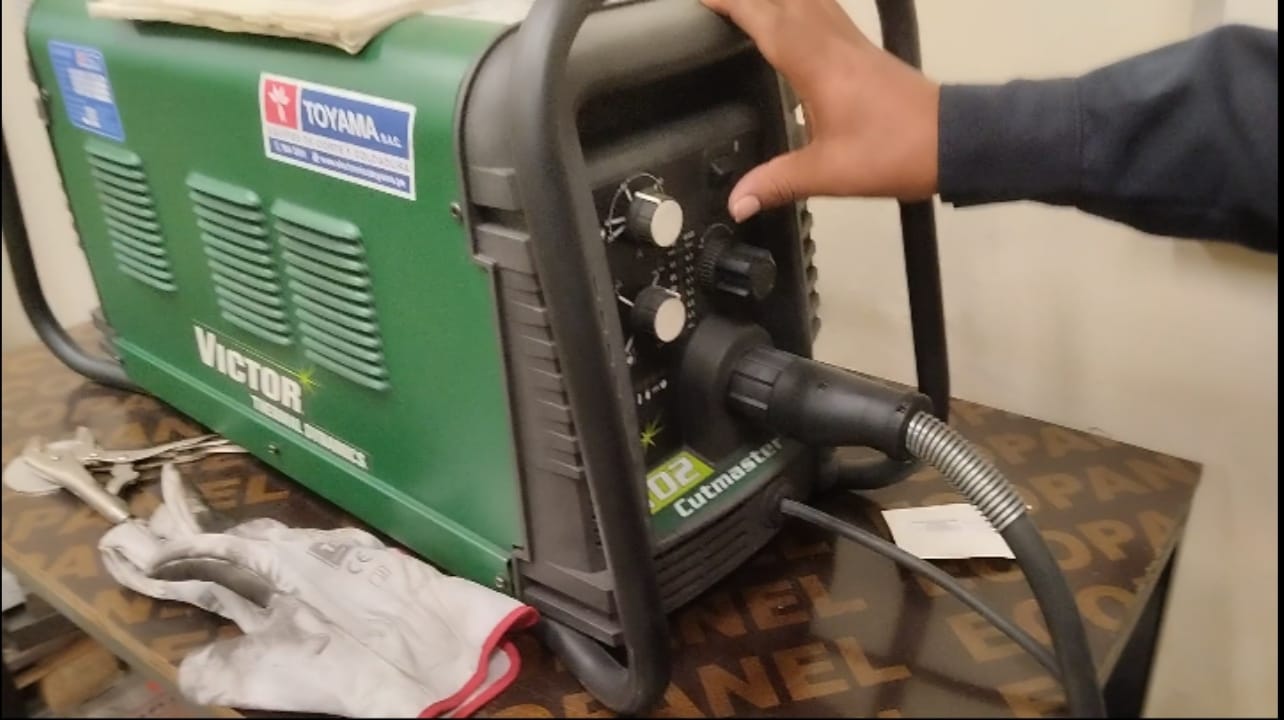
Turn on the plasma generator equipment:
Connect the USB:
Load the file: Edit > USB > Load
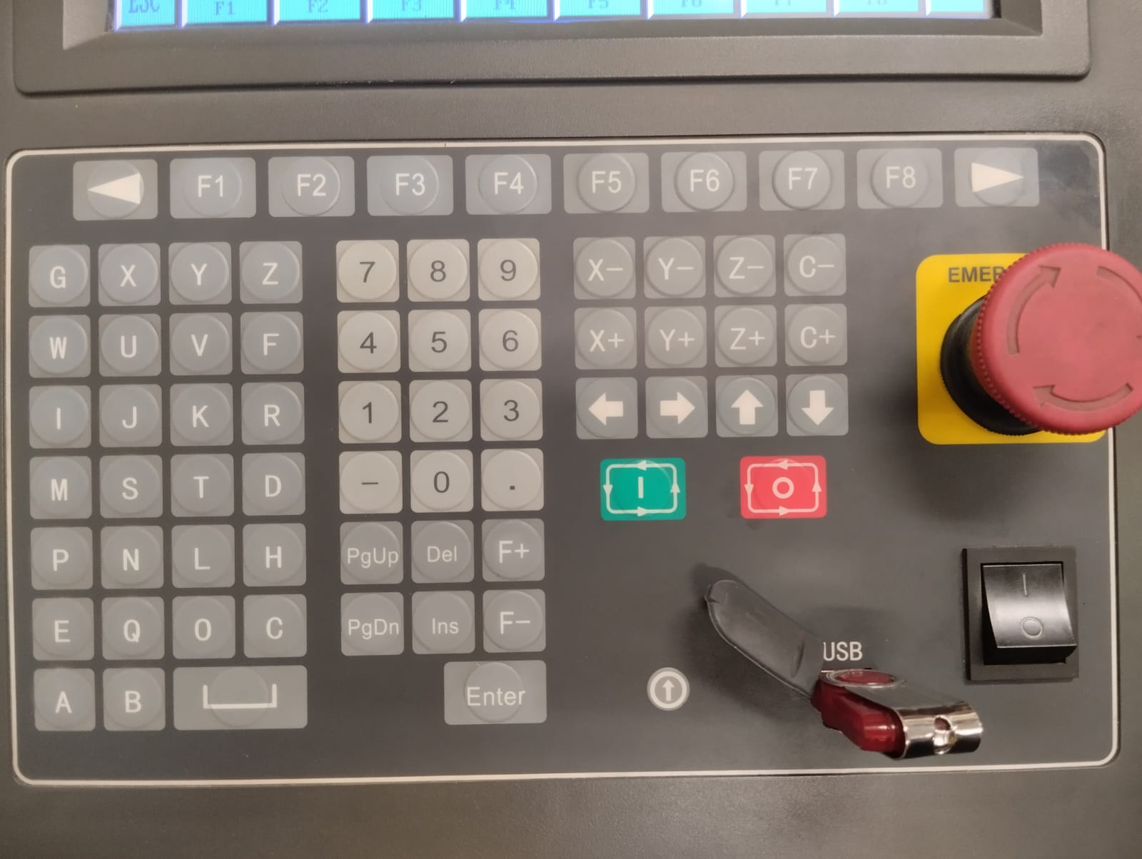
Next, we need to calibrate our X and Y axes. Press the manual option and use the arrows on the control panel to move the axes until the nozzle is positioned at our origin. Then, use the PROG-0 option to update our axes to 0.
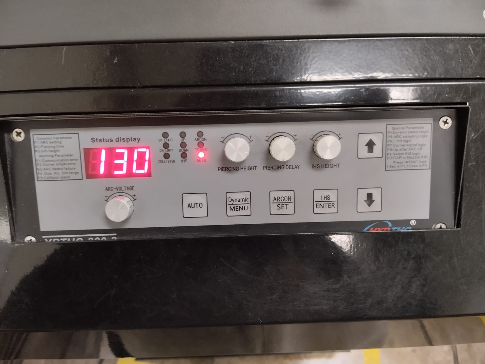
At the bottom of the control panel, modify the parameters based on the data in the table:
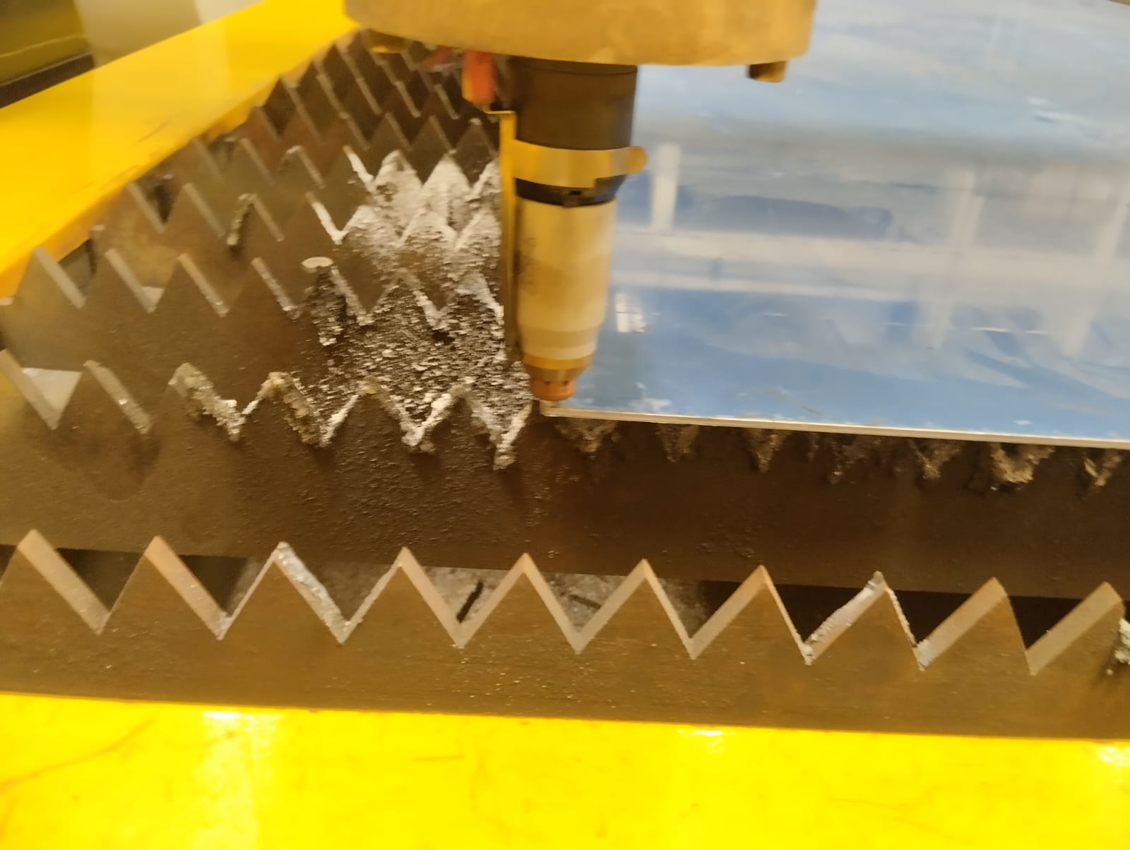
Then, press "Auto" and adjust the feed rate to 1600. Press "Start" on the control panel to initiate the cutting process. Remember to use your safety equipment.
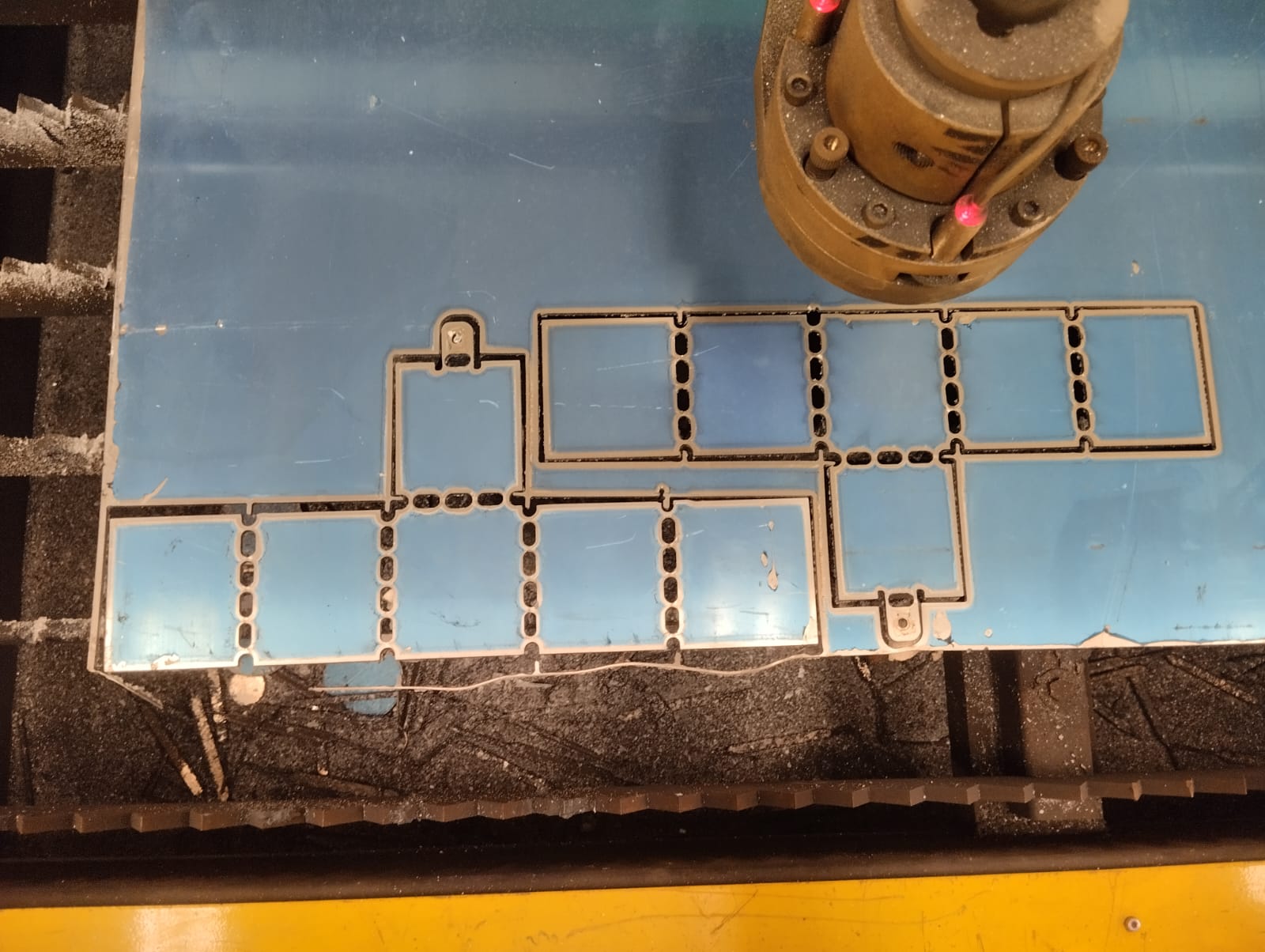
After completing the cut, we can remove the pieces. Remember to wait a bit for them to cool down, although if you are wearing gloves, you can handle them comfortably.
Finally, we use a file to smooth the edges.
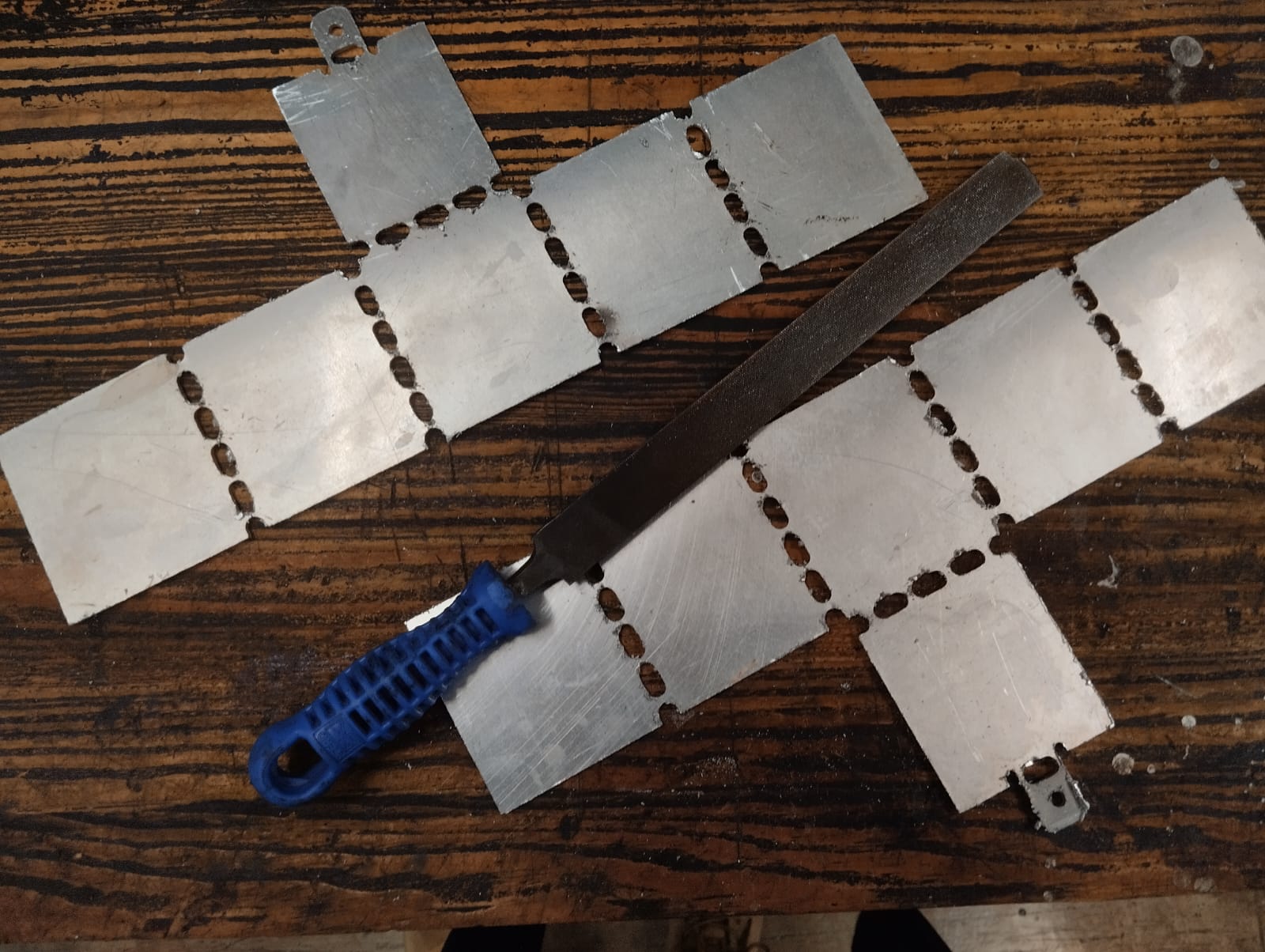
And we test the bending.
Final result:
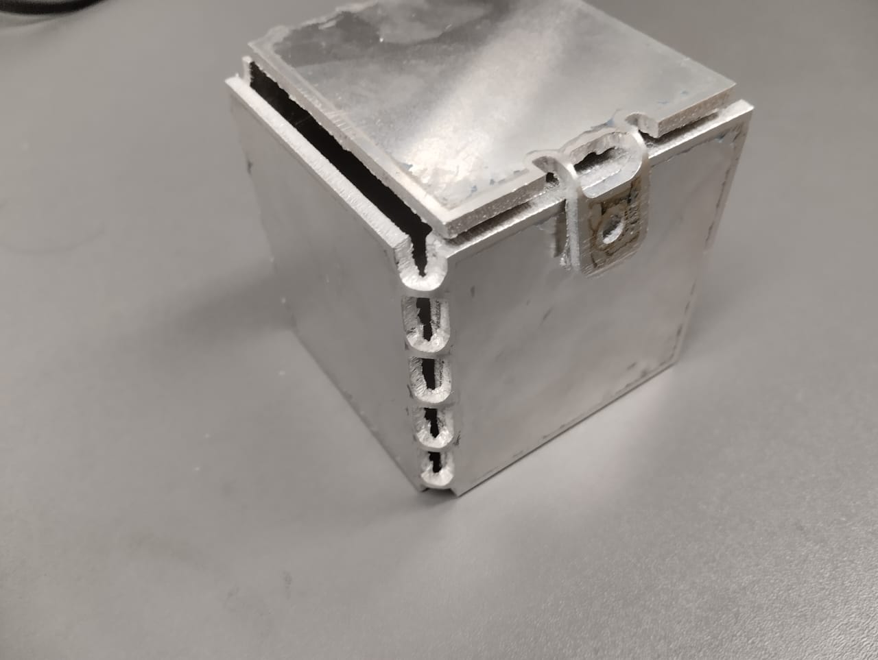
It is important to know that when aluminum is repeatedly folded multiple times, it is prone to breaking due to a combination of factors. Firstly, aluminum undergoes work hardening during deformation, causing internal stresses to accumulate with each fold. These stresses progressively increase the metal's brittleness, making it more susceptible to fracture. Secondly, the repeated folding introduces fatigue, creating microcracks and structural defects that can propagate over time and ultimately lead to failure