Week 7: Computer-Controlled Machining
Week 7: Computer-Controlled Machining
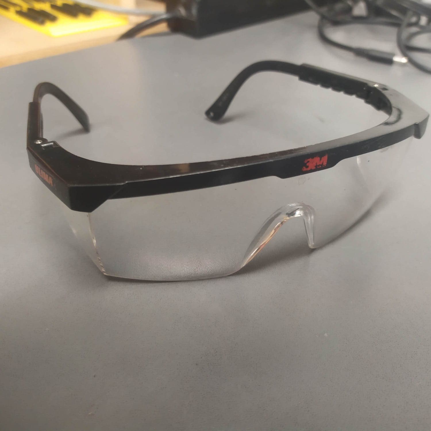
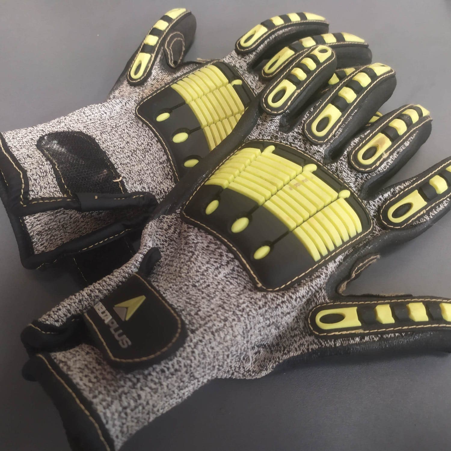
For this week it is important to have personal protective equipment: Insulating steel boots, safety glasses and gloves.

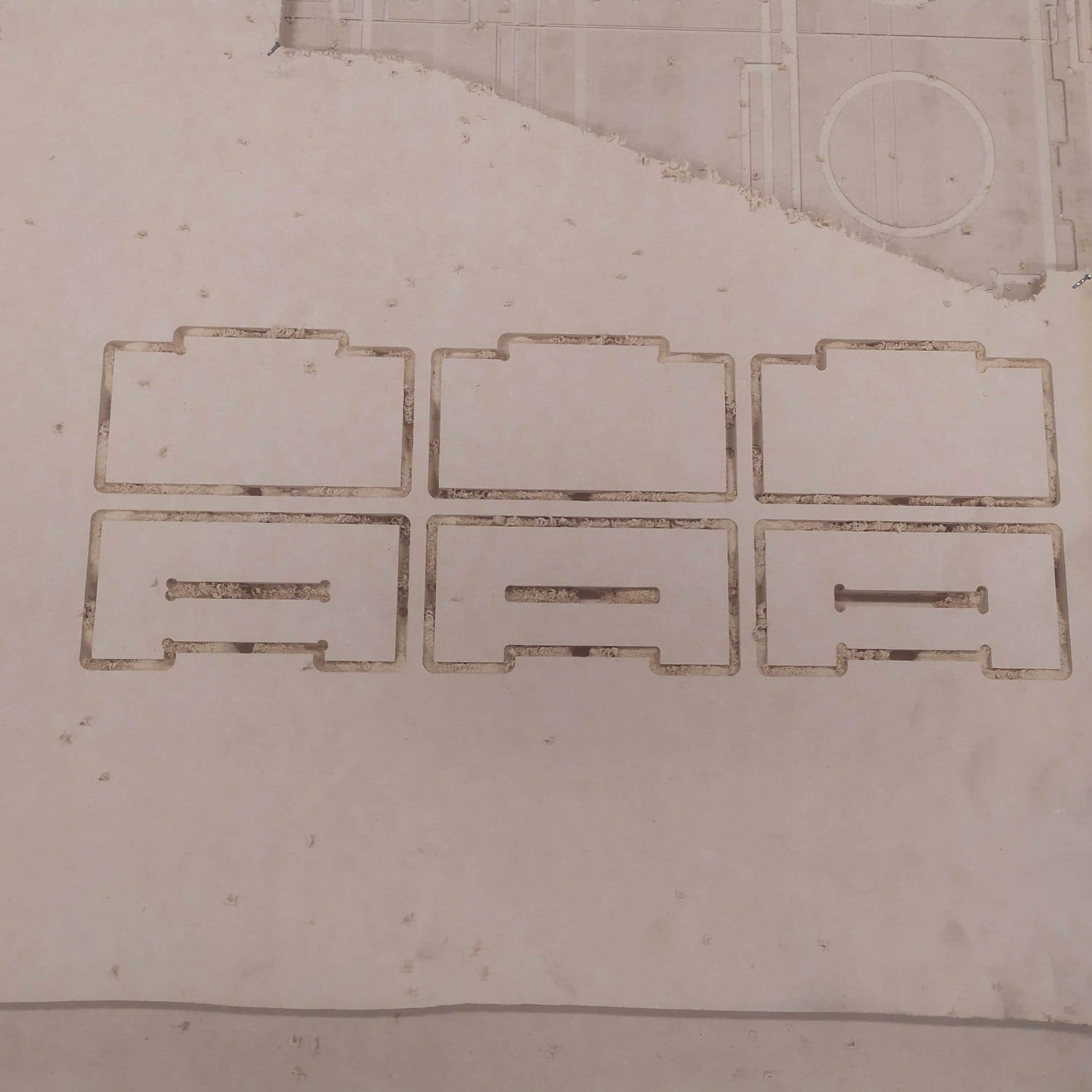
Before carrying out the individual assignment, tests were carried out with 9mm MDF. 3 types of inserts were designed in Fusion360:
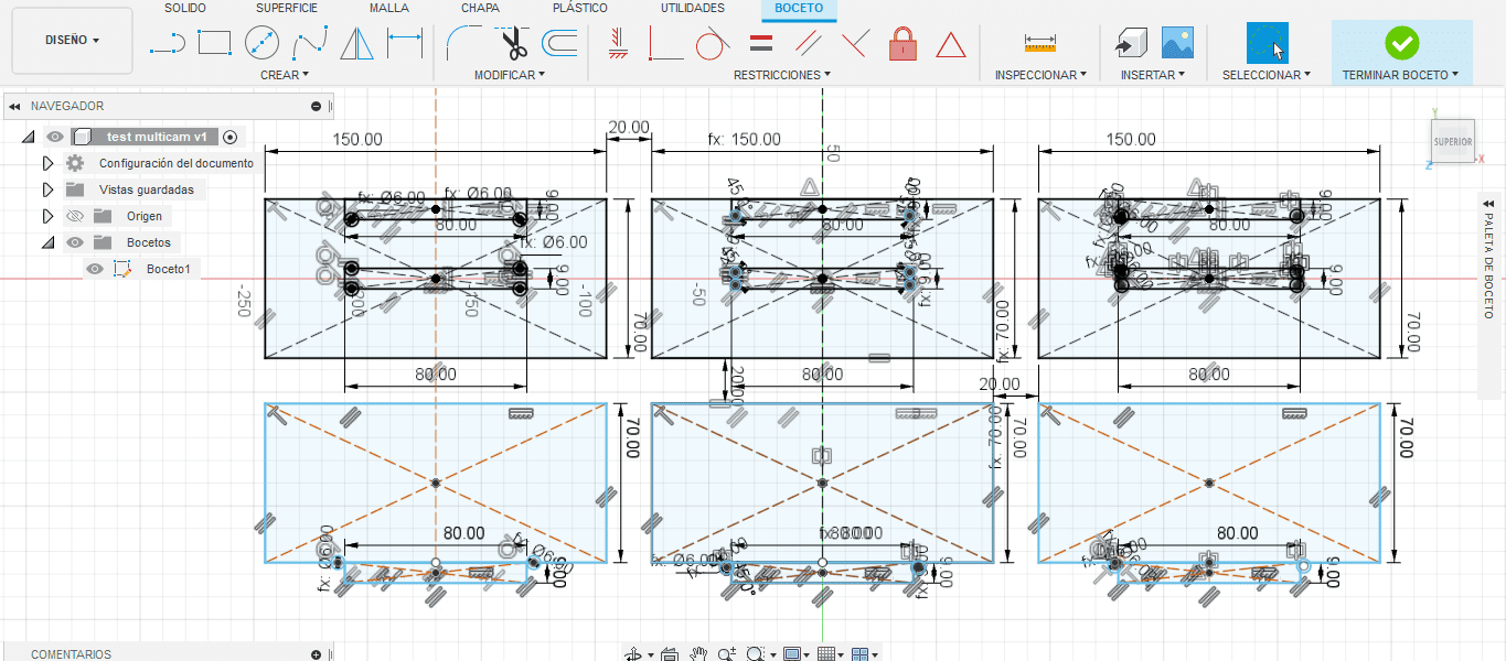
A Tbone can be seen on the left side, on the right a Dog bone and in the center a dog bone with tangent circles to the corners. The projection of the sketch was exported as dxf and taken to the enRoute software, where the parameters were placed to generate the G code. The dimensions of the working area of the machine are placed:
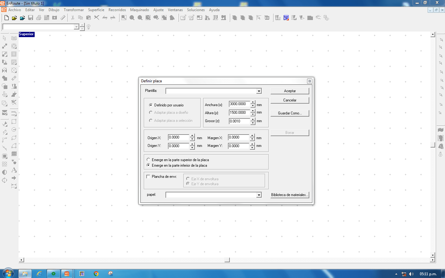
the pieces are positioned, it is advisable to leave a margin of 20mm for each axis. and proceed to fill in the parameters.
After that, we proceed to generate the G code and that´s it.
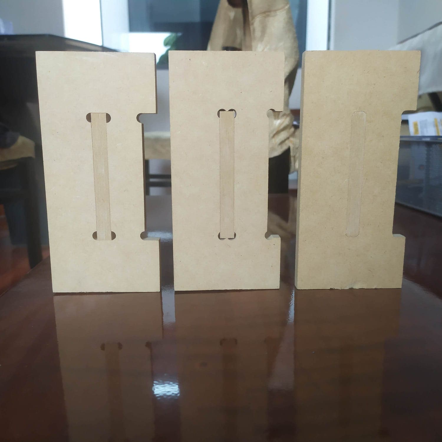
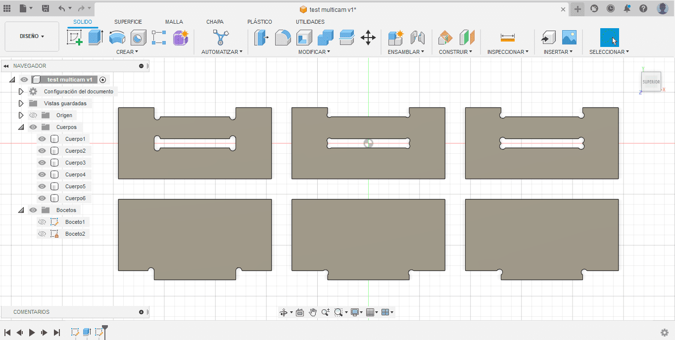
You can see the assembly in T bone, Dog bone and the Dog bone 2 in that order. The latter is more pleasing to the eye, since the holes are almost imperceptible. However, it took more effort to fit the piece and to take it apart.
Well, that`s it…. I know, that was fast. There are many steps that I do not explain in detail, such as the parameters and others that I do not even mention, such as turning on and calibrating the axes of the machine. I didn't want to be redundant because I will explain them in the individual assignment that starts now:
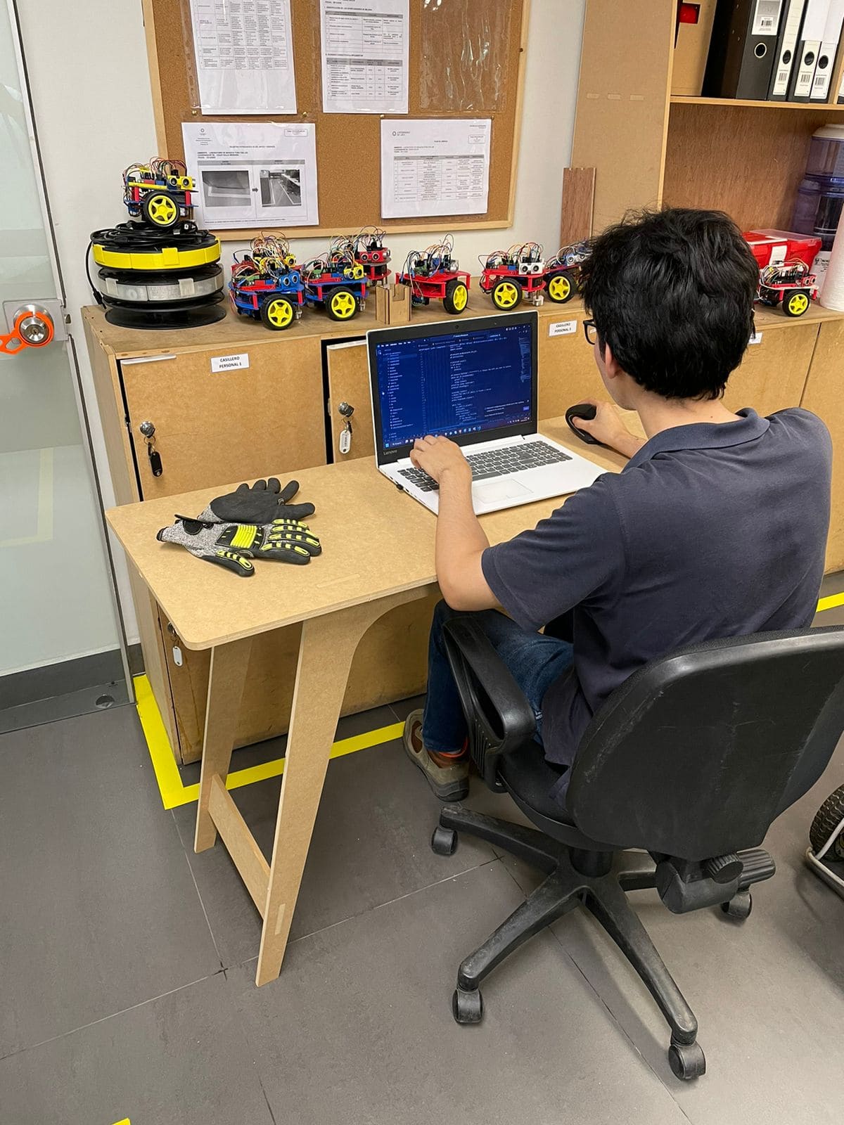
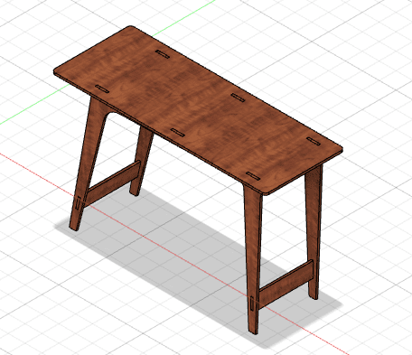
This week's homework is to do something big. At least one dimension must be 1 meter or more. I thought of something I needed and decided to make a table to work with my laptop. I was inspired by some images and videos on the internet and started the first sketches:
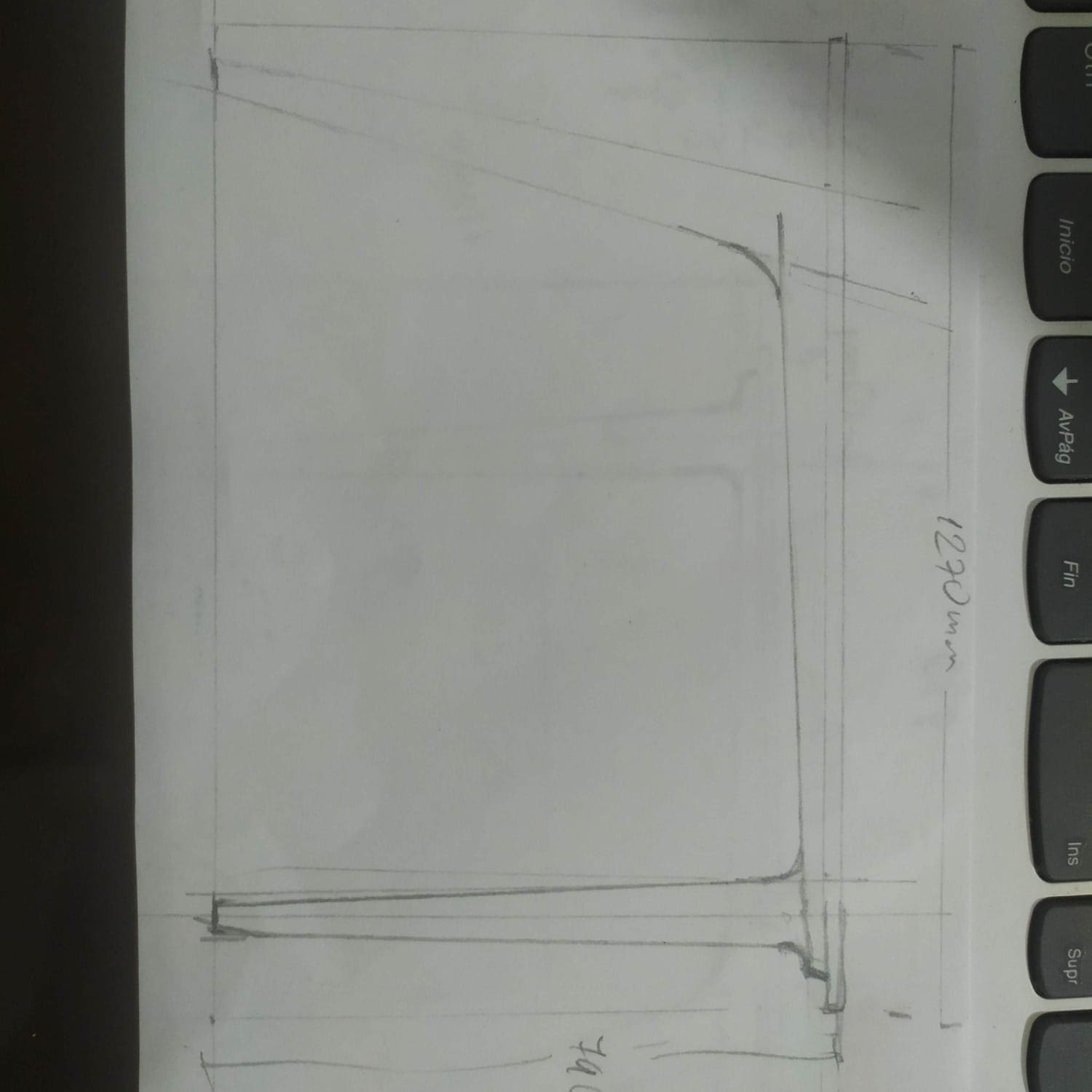
Once the dimensions were thought out, including the thickness of the material to work with, and with the sketch in hand, I proceeded to design in Fusion360.
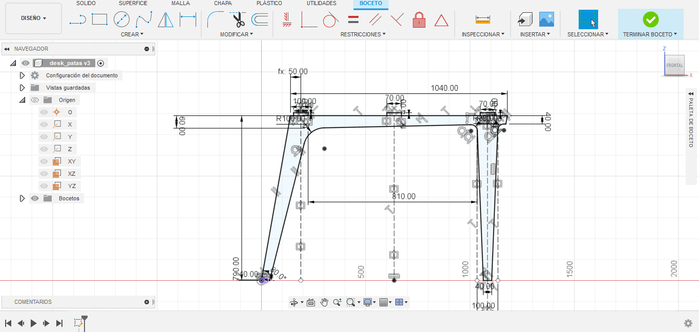
Here you can see the Fusion360 sketch of the legs of the table, all the pieces can be found in the download section at the bottom of this page.
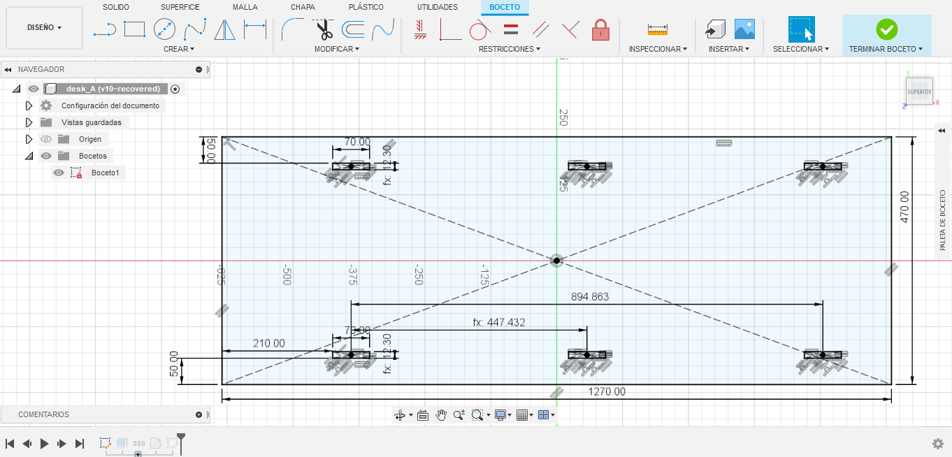
Here is the sketch of part_a:
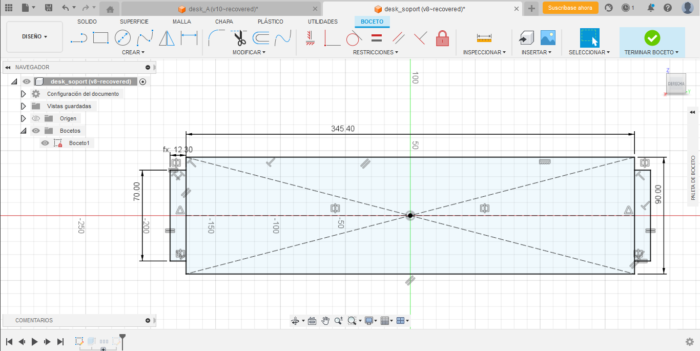
Here is the sketch of part_b that works as braces for the desk:
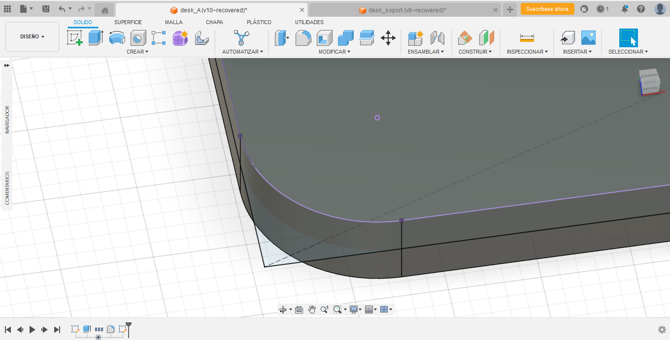
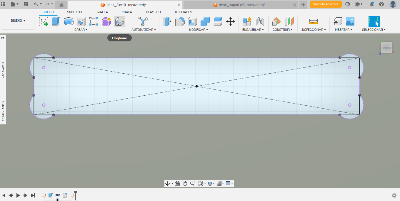
After finishing a sketch, we extrude the face with a thickness of 12mm and add fillets and dogbones.
dogbones:
Finally, we assemble the parts. Here is the assembly in Fusion 360:
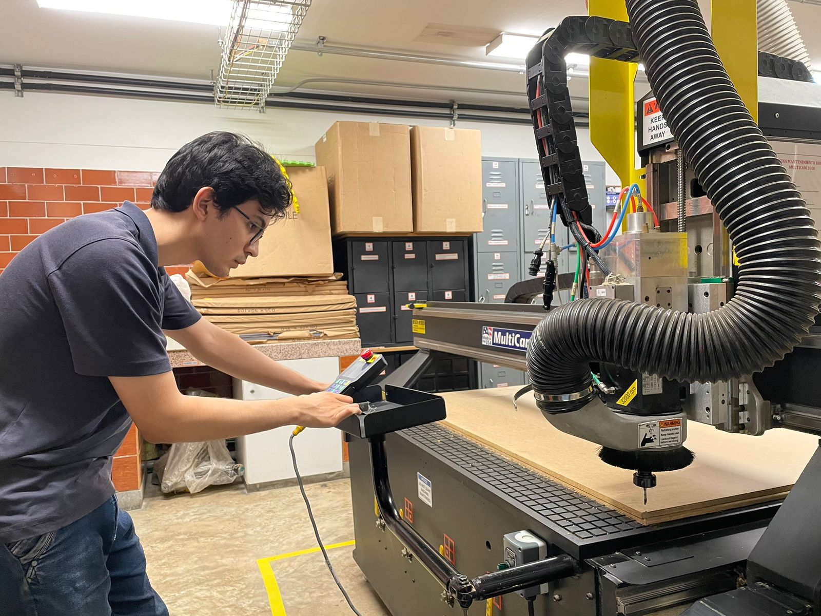
We send the axes to 0 with the combination:
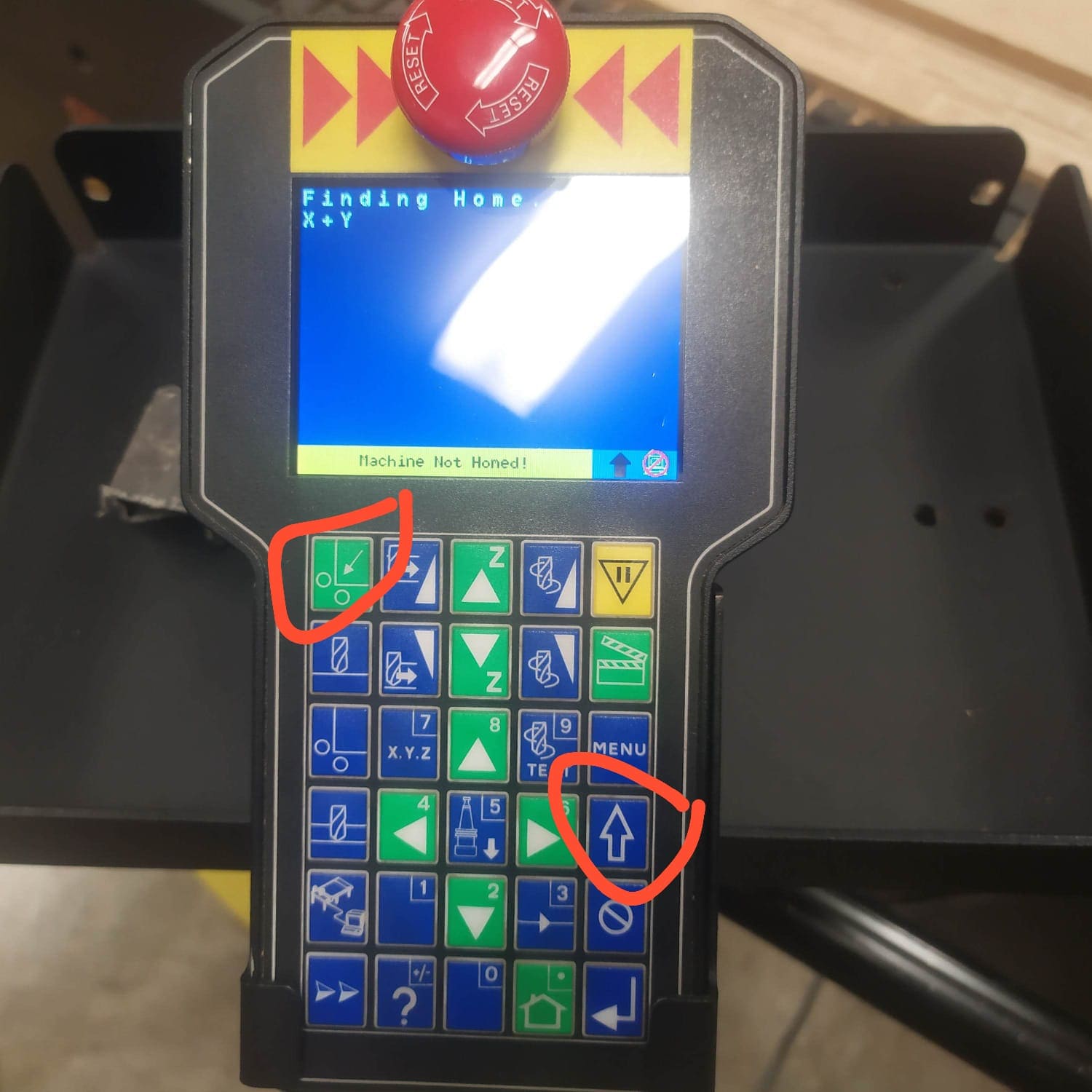
the CNC router will start to move to its default position. Once the machine reaches its position (0,0) we proceed to the warm-up
By pressing the ENTER key we start heating the machine, this will take between 10 to 15 minutes.
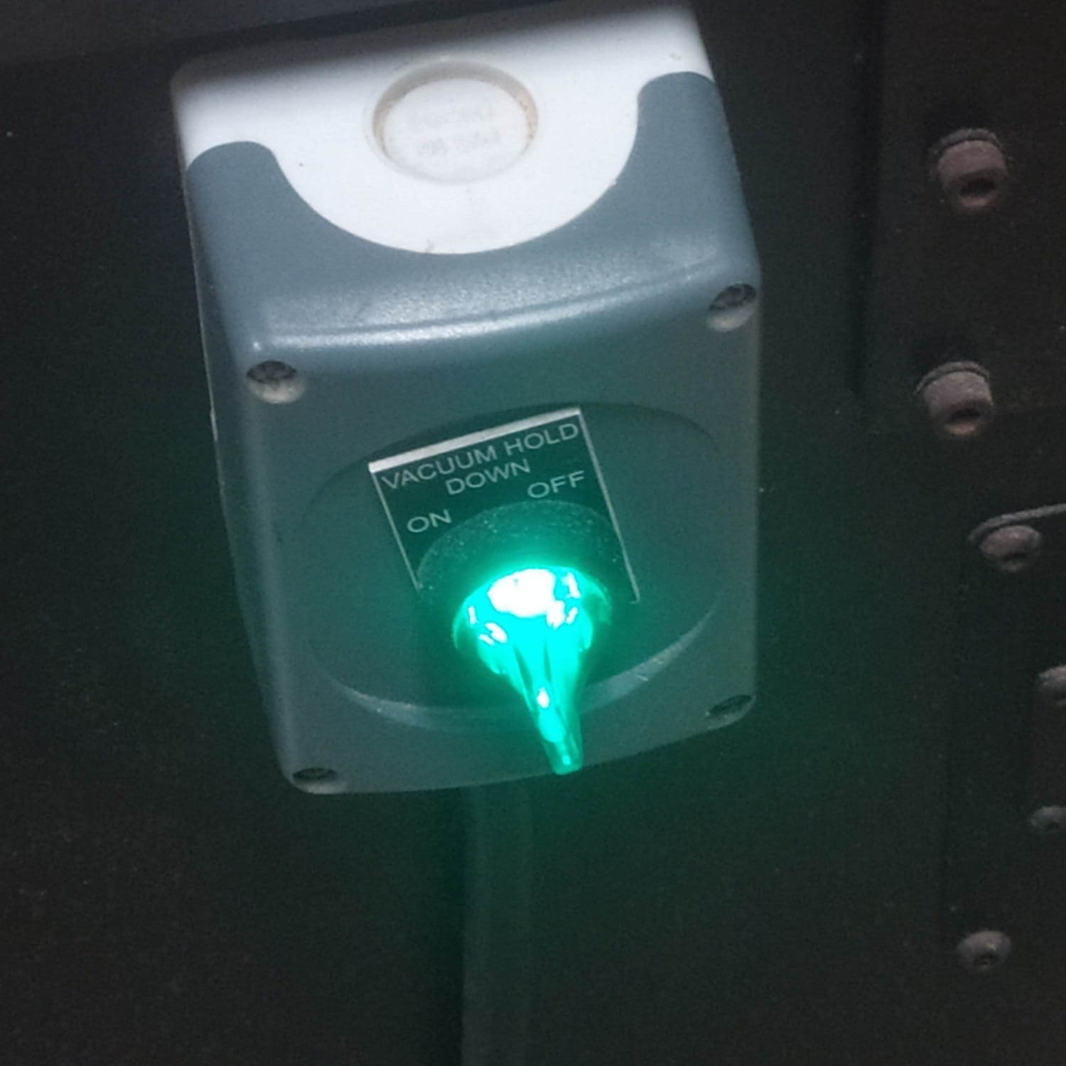
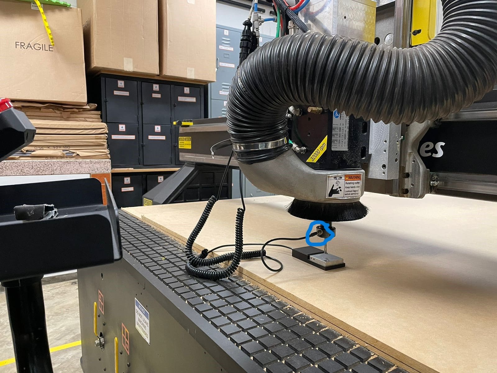
To calibrate the Z axis we approach with the arrows close to the material, then we turn on the vacuum bed:
We position the sensor on the material and connect it as follows:
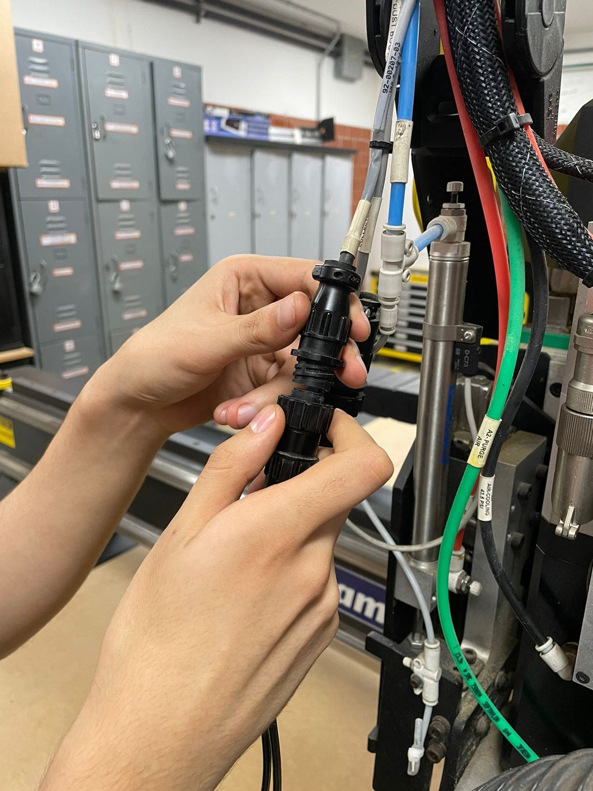
The other end of the sensor is placed in the following position:
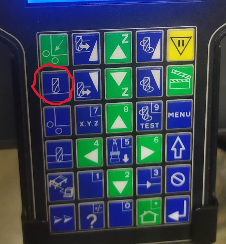
Then the option to calibrate on the material is pressed (an icon of the milling cutter touching the material) >tool1>enter> and 0 is pressed without releasing until the calibration is finished:
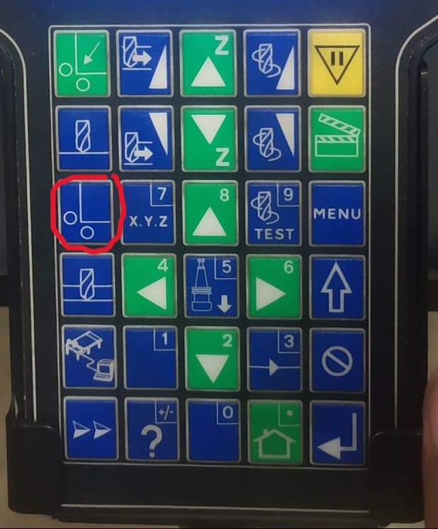
We repeat the same process, but we place the sensor on top of the vacuum bed and press another option to calibrate (unlike the previous option, the cutter is below the material). Once these steps are completed, we remove the sensor and calibrate the X and Y axis. To calibrate the X and Y axis, we use the arrows to set the new (0,0) and press the following key:
Once these steps are done we are ready to send the file. The machine works with G code, so we need to translate our design to this code. There are different software to achieve this, in our case we will use enRoute.
After finishing the design, save the pieces in DXF format to take them to the enRoute software, where they will be positioned according to the measurements of the material that are available. That is why it is very important to first take the measurements of the material. In my case I chose an MDF board 12 mm thick, 2140 mm long and 1200 mm wide. When ordering the pieces in the enroute we must make sure that the final dimensions do not exceed those of the material used.
As I was saying, the pieces are imported to the enroute, then we modify the parameters.
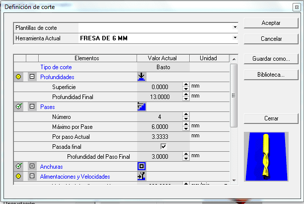
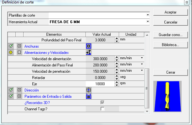
"Current tool" a 6 mm cutter will be used, in "Final Depth" the thickness of the material is placed adding an extra 1 mm, this in order to ensure that the mill cuter completely goes through the material, remember that under the material we have a slaughter bed so there is no inconvenience, in our specific case we will use a 12 mm thick material so we place 13 mm. In the Passes section, we set the "Maximum per Pass" to 6mm, it is recommended that it not exceed the diameter of the cutter. If we wish, we can activate the final pass box and place “Final Pass Depth”, a parameter that indicates the depth of the last pass. The rest of the parameters in the Passes section are automatically calculated by filling in the aforementioned values.
In the Feed and speed section, the values shown in the image are placed, these are good references for 2D cutting jobs like the one we will carry out. It should be noted that the penetration speed is generally half the feeding speed (advance). The Axis parameter indicates the rpm at which the mill rotates. The rest of the parameters are not necessary for the work we are doing.
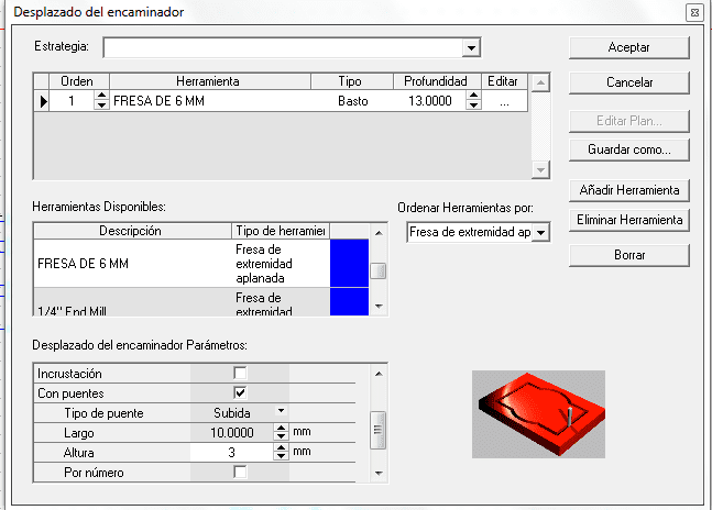
It is recommended to activate the "bridge" option in the software, we use the manual option with a length and width of 10 x 3 mm per tabs, accept is placed and we choose the places where we want the tabs.
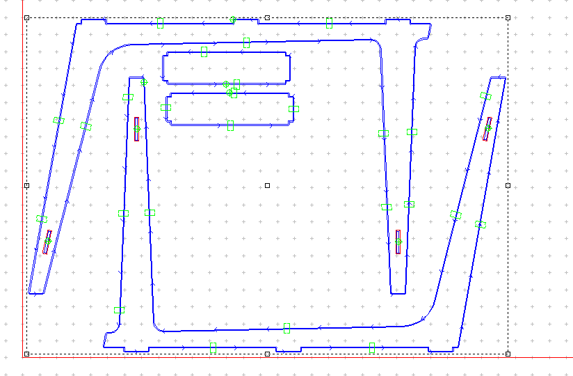
The green boxes are the tabs that we placed. Then in the "output G1" icon we can generate the G code:
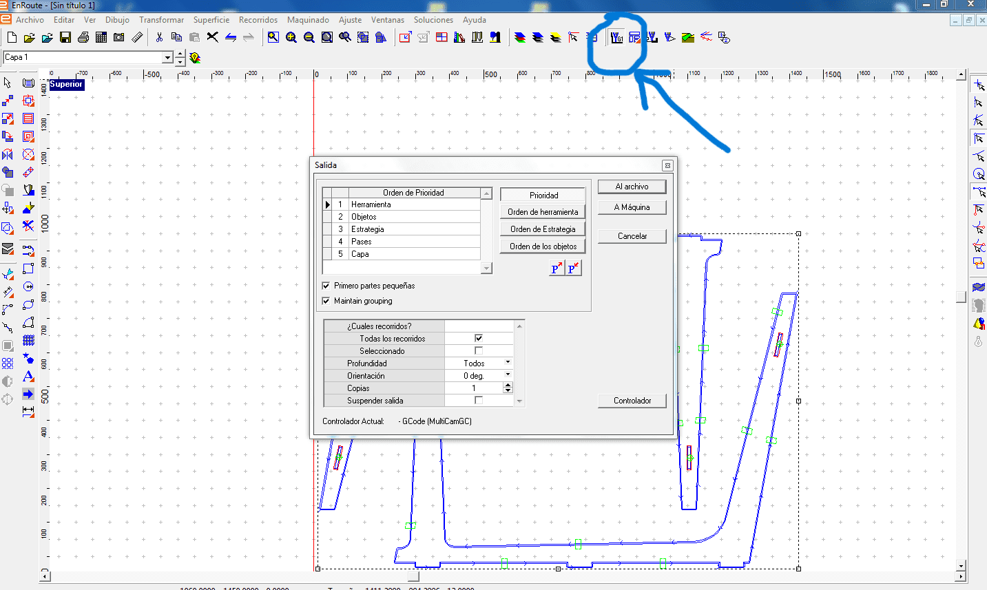
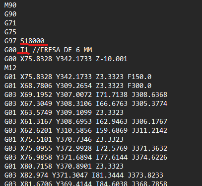
We make sure that in the generated G code Tool 1 (T1) is used.
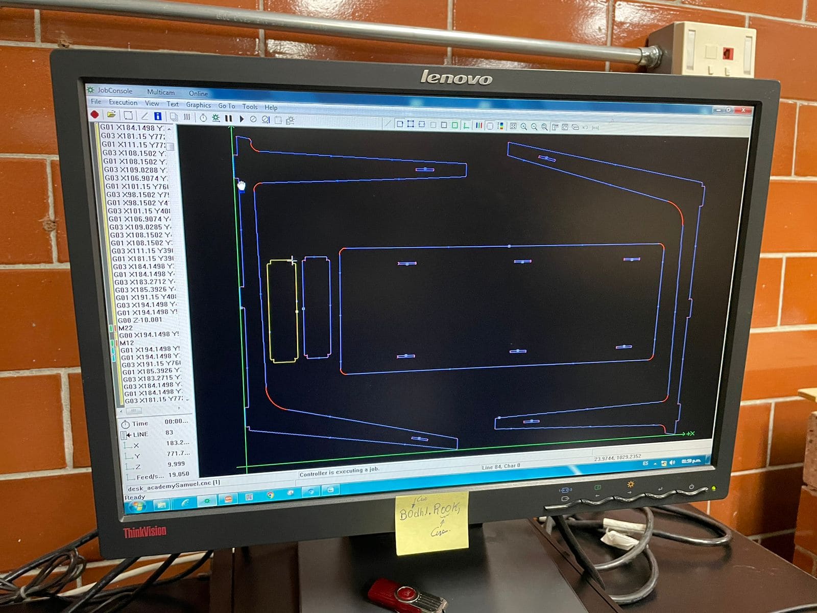
Finally we open the code in Jobconsole and send the code to the machine with the option to execute.
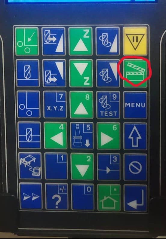
Initialize the job on the CNC. After sending the G code from the Jobconsole, all that remains is to press the following button to start the job
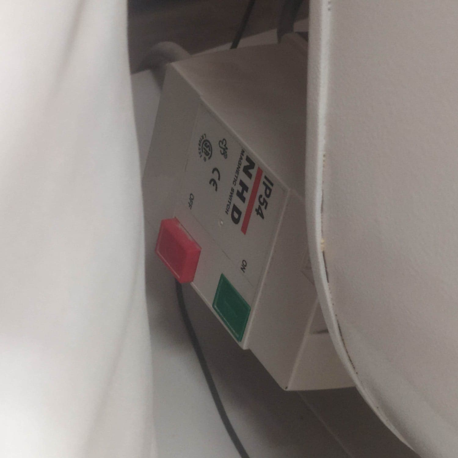
Remember to turn on the extractor before it starts cutting.
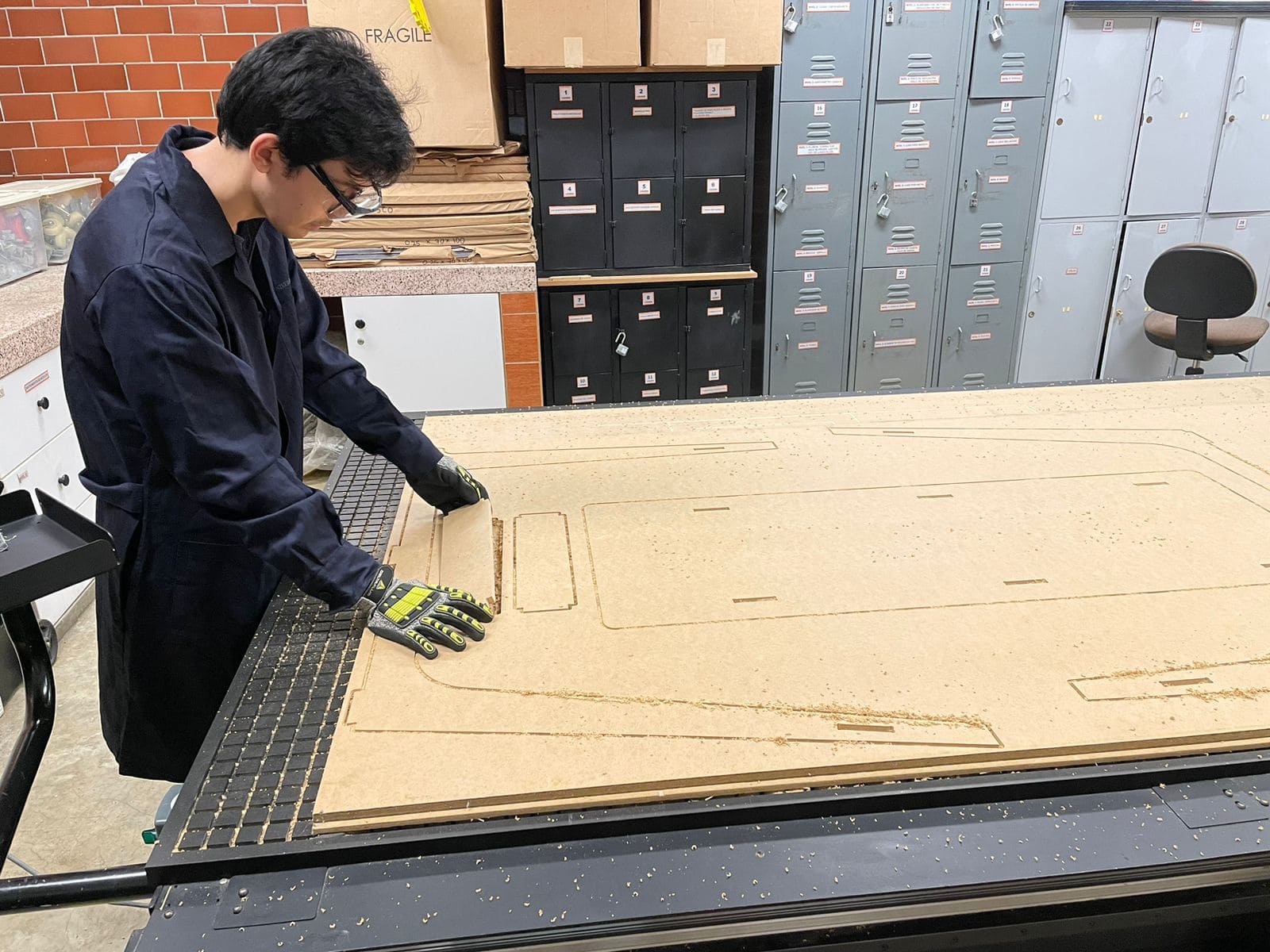
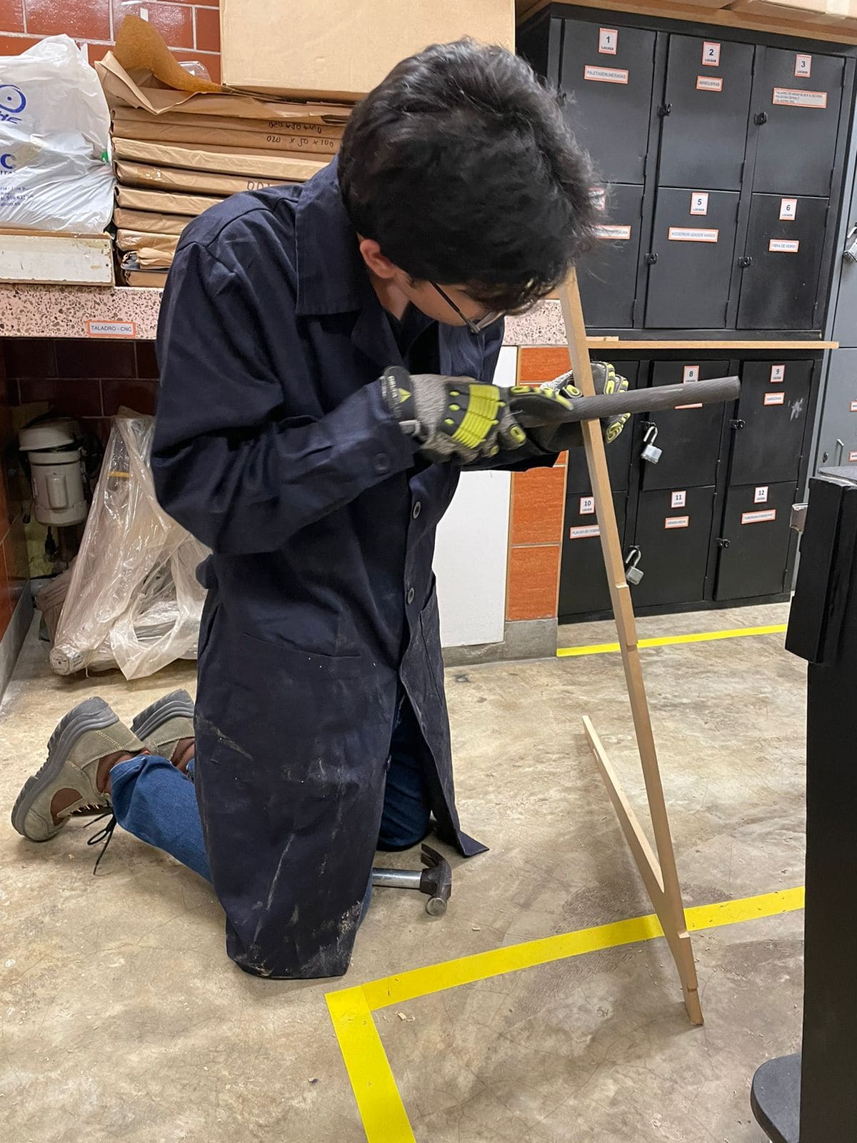
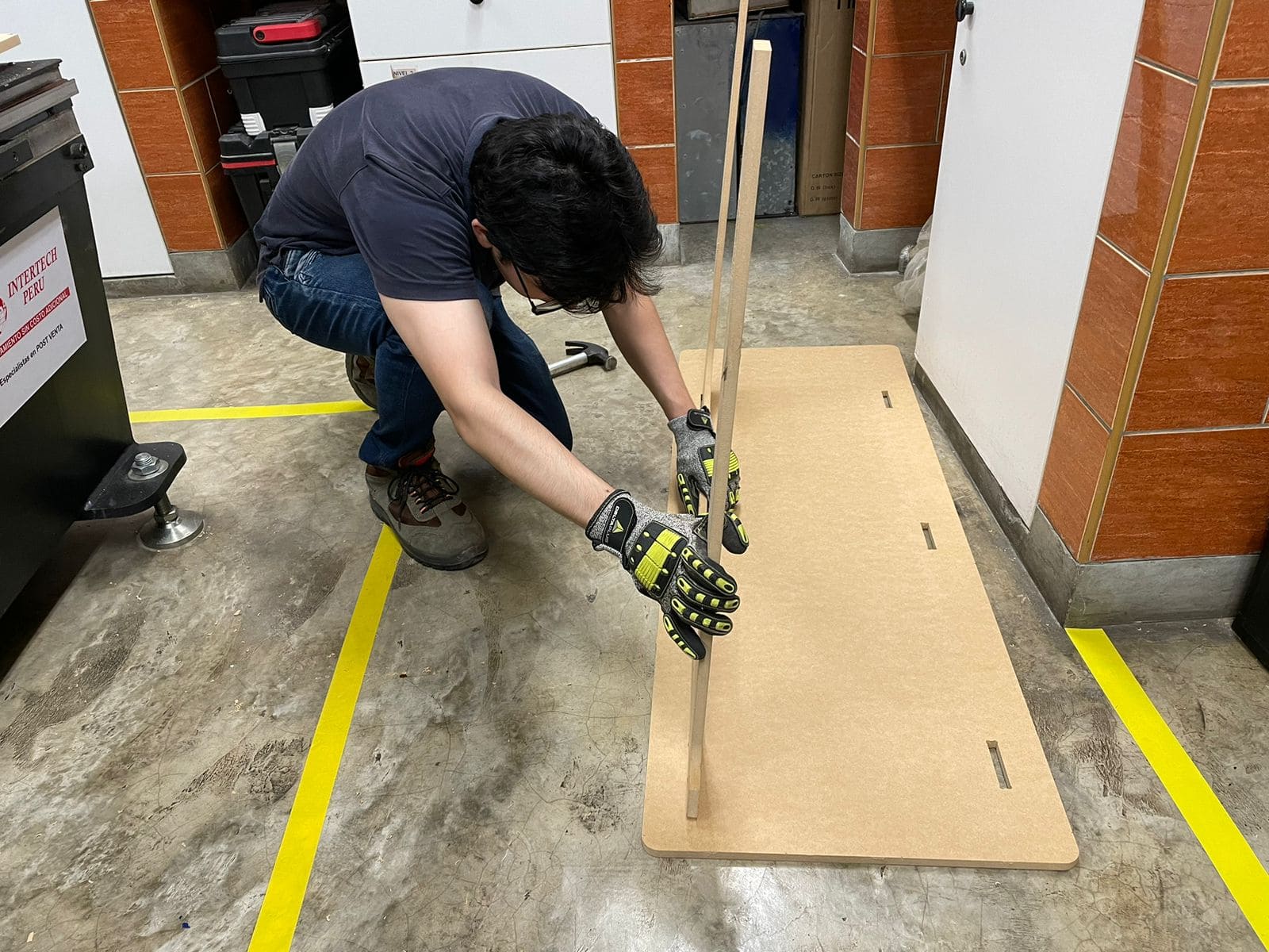
You can help yourself with a rubber hammer to make sure that your pieces are well assemble